Description
File Details
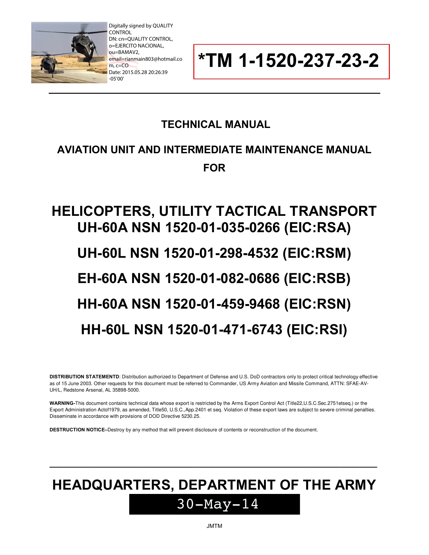
- Manual type: Aviation Unit and Intermediate Maintenance Manual (troubleshooting procedures, Volume 2)
- Document number: TM 1-1520-237-23-2
- Brand / models: U.S. Army utility tactical transport helicopters UH-60A NSN 1520-01-035-0266 (EIC:RSA), UH-60L NSN 1520-01-298-4532 (EIC:RSM), EH-60A NSN 1520-01-082-0686 (EIC:RSB), HH-60A NSN 1520-01-459-9468 (EIC:RSN), HH-60L NSN 1520-01-471-6743 (EIC:RSI)
- Language: English
- Page count: 1087
- File format: PDF
- Publication date: 30 May 2014 (Headquarters, Department of the Army)
- Noted change marking: Change 5, 31 March 2014 on selected work packages
- PIN: 073172-000
What This Volume Covers
The UH-60A UH-60L EH-60A HH-60A HH-60L Aviation Unit Intermediate Maintenance Troubleshooting Manual TM 1-1520-237-23-2 Volume 2 is the Chapter 2 troubleshooting book for Army utility tactical transport helicopters. It is not a full multi-volume remove-and-replace set. Work packages walk a unit or intermediate technician from an operational checkout through symptoms, malfunctions, voltage and continuity checks, linkage inspections, and corrective actions that point to a follow-on work package or to engine TM 1-2840-248-23 when the airframe is cleared.
Model-specific callouts appear throughout. IVHMS paths are written for UH-60A and UH-60L. Multifunction display caution and advisory grids are written for HH-60A and HH-60L. EDECU warnings apply to H60A/L aircraft that must not have the Discrete Application Selection plug installed. Central display units, signal data converters, and caution/advisory panels are split by part number so the correct AVIM bench procedure is used.
Chapters Covered
Volume 2 opens with the warning summary, then a single chapter of aviation unit and intermediate troubleshooting procedures.
Complete PDF Bookmark Tree
Complete Bookmarks
The complete bookmarks in the “UH-60A UH-60L EH-60A HH-60A HH-60L Aviation Unit Intermediate Maintenance Troubleshooting Manual TM 1-1520-237-23-2 Volume 2” are as follows:
+Binder1p. 1
TM 1-1520-237-23-2 TROUBLESHOOTING PROCEDURES 1p. 1
TM 1-1520-237-23-2 TROUBLESHOOTING PROCEDURES 2p. 2
TM 1-1520-237-23-2 TROUBLESHOOTING PROCEDURES 3p. 3
TM 1-1520-237-23-2 TROUBLESHOOTING PROCEDURES 4p. 4
TM 1-1520-237-23-2 TROUBLESHOOTING PROCEDURES 5p. 5
+Binder2p. 6
+wp0072p. 6
+tocp. 6
+Position Transmitter/Limit Switch Assembly (AVIM)p. 6
Position Transmitter/Limit Switch Assembly (AVIM) Operational/Trp. 6
Schematicsp. 11
+wp0073p. 12
+tocp. 12
+Parking Brake Systemp. 12
Parking Brake System Operational/Troubleshooting Procedurep. 12
Brake Pedals Bottom Out (No Resistance Felt)p. 14
PARKING BRAKE ON Capsule Does Not Go Onp. 14
Brakes Do Not Holdp. 15
Schematicsp. 19
+wp0074p. 25
+tocp. 25
+Tail Wheel Lock Systemp. 25
Tail Wheel Lock System Operational/Troubleshooting Procedurep. 25
Tail Wheel Lockpin Does Not Disengage And Tail Wheel Switch Indip. 26
Tail Wheel Lockpin Disengages, But Tail Wheel Switch Indicates Lp. 28
Tail Wheel Lockpin Does Not Engage And Tail Wheel Switch Indicatp. 29
Tail Wheel Lockpin Engages, But Tail Wheel Switch Indicates UNLKp. 30
Schematicsp. 33
+wp0075p. 35
+tocp. 35
+Engine And Engine Interfacep. 35
Engine and Engine Interface Introduction Operational/Troubleshoop. 35
Engine Ng Low At Ground Idle Speed (Idle Speed Below Limits)p. 36
Engine Ng High At Ground Idle Speed (Idle Speed Above Limits)p. 37
Engine Flames Outp. 37
Engine TGT Fluctuates At Ground Idle Speedp. 38
Engine TGT Exceeds Limiter Settingp. 38
Engine Has Uncontrolled Acceleration (Ng)p. 38
Engine Has Unstable Operation (Ng, Np, And Torque)p. 39
Torque Split Greater Than 5% Or Erraticp. 39
BITE Reads 125%p. 40
BITE Reads 115% Or During Power Recovery, Np Does Not Increase Tp. 41
TGT Spikes On Either Enginep. 42
TGT And/Or Torque Spiking Appear On PDUs Without Associated Chanp. 47
Load Demand Spindle Verificationp. 49
Schematicsp. 53
+tablesp. 35
Table 1. Self-test BITE Indications.p. 36
+wp0076p. 54
+tocp. 54
+No. 1 Engine Instruments and Warning Lights Systemp. 54
No. 1 Engine Instruments And Warning Lights System Operational/Tp. 54
#1 FUEL PRESS Capsule Or Legend Does Not Go Onp. 57
#1 ENGINE OIL PRESS Capsule Or Legend Does Not Go Onp. 58
#1 OIL FLTR BYPASS Capsule Or Legend Does Not Go Onp. 59
#1 FUEL FLTR BYPASS Capsule Or Legend Does Not Go Onp. 60
#1 FUEL PRESS Capsule Or Legend Remains On When Engine Is At Idlp. 61
No. 1 Engine Oil Pressure (ENG OIL PRESS 1) Is Below Minimum Limp. 61
No. 1 Engine Oil Temperature (ENG OIL TEMP 1) Is Too High Or Hasp. 62
No. 1 Engine Has No Gas Generator (% Ng 1) Indicationp. 63
No. 1 Engine Turbine Inlet Temperature (TGT TEMP 1) Has No Indicp. 63
No. 1 Engine Oil Fluctuates Greater Than 5 PSI Or Is Too High (1p. 64
No. 1 Engine Oil Has No Oil Pressure Indicationp. 66
No. 1 Engine Has No Power Turbine Speed (%RPM ENG 1) Indicationp. 66
No. 1 Engine Has No Torque (%TRQ 1) Indicationp. 67
Schematicsp. 70
+wp007601p. 75
+tocp. 75
+No. 1 Engine Instruments and Warning Lights System UH-60A UH-6p. 75
No. 1 Engine Instruments And Warning Lights System Operational/p. 75
#1 FUEL PRESS CAPSULE DOES NOT GO ONp. 78
#1 ENGINE OIL PRESS CAPSULE DOES NOT GO ONp. 79
#1 OIL FLTR BYPASS CAPSULE DOES NOT GO ONp. 80
#1 FUEL FLTR BYPASS CAPSULE DOES NOT GO ONp. 81
#1 FUEL PRESS CAPSULE REMAINS ON WHEN ENGINE IS AT IDLE SPEEDp. 82
NO. 1 ENGINE OIL PRESSURE (ENG OIL PRESS 1) IS BELOW MINIMUM LIMp. 82
NO. 1 ENGINE OIL TEMPERATURE (ENG OIL TEMP 1) IS TOO HIGH OR HASp. 83
NO. 1 ENGINE HAS NO GAS GENERATOR (% NG 1) INDICATIONp. 84
NO. 1 ENGINE TURBINE GAS TEMPERATURE (TGT TEMP 1) HAS NO INDICATp. 85
NO. 1 ENGINE OIL FLUCTUATES GREATER THAN 5 PSI OR IS TOO HIGH (1p. 86
NO. 1 ENGINE OIL HAS NO OIL PRESSURE INDICATIONp. 87
NO. 1 ENGINE HAS NO POWER TURBINE SPEED (%RPM ENG 1) INDICATIONp. 88
NO. 1 ENGINE HAS NO TORQUE (%TRQ 1) INDICATIONp. 90
Schematicsp. 94
+wp0077p. 98
+tocp. 98
+No. 2 Engine Instruments and Warning Lights Systemp. 98
No. 2 Engine Instruments And Warning Lights System Operational/Tp. 98
#2 FUEL PRESS Capsule Or Legend Does Not Go Onp. 101
#2 ENGINE OIL PRESS Capsule Or Legend Does Not Go Onp. 102
#2 OIL FLTR BYPASS Capsule Or Legend Does Not Go Onp. 103
#2 FUEL FLTR BYPASS Capsule Or Legend Does Not Go Onp. 104
#2 FUEL PRESS Capsule Or Legend Stays On When Engine Is At Idlep. 105
No. 2 Engine Oil Pressure Is Below Minimump. 106
No. 2 Engine Oil Temperature (ENG OIL TEMP 2) Is Too High Or Hasp. 106
No. 2 Engine Has No Gas Generator (%Ng 2) Indicationp. 107
No. 2 Engine Turbine Inlet Temperature (TGT TEMP 2) Has No Indicp. 108
No. 2 Engine Oil Pressure (ENG OIL PRESS 2) Fluctuates Greater Tp. 109
No. 2 Engine Has No Oil Pressure Indicationp. 110
No. 2 Engine Has No Power Turbine Speed (%RPM ENG 2) Indicationp. 111
No. 2 Engine Has No Torque (%TRQ 2) Indicationp. 111
Schematicsp. 117
+wp007701p. 122
+tocp. 122
+No. 2 Engine Instruments and Warning Lights System UH-60A UH-60p. 122
No. 2 Engine Instruments And Warning Lights System Operational/Tp. 122
#2 FUEL PRESS Capsule Does Not Go Onp. 125
#2 ENGINE OIL PRESS CAPSULE DOES NOT GO ONp. 126
#2 OIL FLTR BYPASS Capsule Does Not Go Onp. 127
#2 FUEL FLTR BYPASS Capsule Does Not Go Onp. 128
#2 FUEL PRESS Capsule Stays On When Engine Is At Idle Speedp. 129
No. 2 Engine Oil Pressure Is Below Minimump. 129
No. 2 Engine Oil Temperature (ENG OIL TEMP 2) Is Too High Or Hasp. 130
No. 2 Engine Has No Gas Generator (%Ng 2) Indicationp. 131
NO. 2 ENGINE TURBINE GAS TEMPERATURE (TGT TEMP 2) HAS NO INDICATp. 132
No. 2 Engine Oil Pressure (ENG OIL PRESS 2) Fluctuates Greater Tp. 133
No. 2 Engine Has No Oil Pressure Indicationp. 134
No. 2 Engine Has No Power Turbine Speed (%RPM ENG 2) Indicationp. 135
No. 2 Engine Has No Torque (%TRQ 2) Indicationp. 136
Schematicsp. 141
+wp0078p. 145
+tocp. 145
+Engine Overspeed Protection Systemp. 145
Engine Overspeed Protection System Operational/Troubleshooting Pp. 145
No. 1 Engine Overspeed Cuts In When TEST A Button Is Pressedp. 147
No. 1 Engine Overspeed Cuts In When TEST B Button Is Pressedp. 148
No. 1 Engine Does Not Shut Down With Overspeed Conditionp. 149
No. 2 Engine Overspeed Cuts In When TEST A Button Is Pressedp. 150
No. 2 Engine Overspeed Cuts In When TEST B Button Is Pressedp. 151
No. 2 Engine Does Not Shut Down With Overspeed Conditionp. 151
No. 1 Engine BITE Reads 85%p. 153
No. 2 Engine BITE Reads 85%p. 153
Schematicsp. 159
+wp0079p. 162
+tocp. 162
+Engine Speed Trim Systemp. 162
Engine Speed Trim System Operational/Troubleshooting Procedurep. 162
No. 1 And No. 2 Engine Power Turbine Speed (%Np) Cannot Be Decrep. 164
No. 1 Engine Power Turbine Speed (%Np) Cannot Be Increased Or Dep. 165
No. 2 Engine Power Turbine Speed (%Np) Cannot Be Increased Or Dep. 167
Schematicsp. 171
+wp0080p. 175
+tocp. 175
Engine Chip Detector Systemp. 175
+Special Instructionsp. 175
Engine No. 1 Operational/Troubleshooting Procedurep. 175
Engine No. 2 Operational/Troubleshooting Procedurep. 177
CHIP #1 ENGINE Capsule Or Legend Does Not Go Onp. 178
CHIP #2 ENGINE Capsule Or Legend Does Not Go Onp. 179
Schematicsp. 185
+wp0081p. 186
+tocp. 186
Engine Anti-ice Systemp. 186
+Special Instructionsp. 186
No. 1 Engine Operational/Troubleshooting Procedurep. 186
No. 2 Engine Operational/Troubleshooting Procedurep. 189
#1 ENG ANTI-ICE ON Capsule Or Legend Does Not Go On When Enginep. 191
#1 ENG INLET ANTI-ICE ON Capsule Or Legend Does Not Go On When Ap. 193
#1 ENG ANTI-ICE ON Capsule Or Legend Does Not Go Off Immediatelyp. 194
#1 ENG INLET ANTI-ICE ON Capsule Or Legend Does Not Go Off Whenp. 195
#2 ENG ANTI-ICE ON Capsule Or Legend Does Not Go On When Enginep. 196
#2 ENG INLET ANTI-ICE ON Capsule Or Legend Does Not Go On When Ap. 197
#2 ENG ANTI-ICE ON Capsule Or Legend Does Not Go Off Immediatelyp. 199
#2 ENG INLET ANTI-ICE ON Capsule Or Legend Does Not Go Off Whenp. 199
Schematicsp. 207
+wp0082p. 211
+tocp. 211
Engine Start and Ignition Systemp. 211
+Special Instructionsp. 211
No. 1 Engine Operational/Troubleshooting Procedurep. 212
No. 2 Engine Operational/Troubleshooting Procedurep. 215
PRIME BOOST PUMP ON Capsule Or Legend Goes On When Power Is Applp. 218
No. 1 Engine Does Not Start (Compressor Not Rotating) (#1 ENGINEp. 219
Engine Starter Motors Engine, But Cannot Reach Proper Ng Speed Tp. 220
No. 1 Engine Does Not Start (Compressor Not Rotating) (#1 ENGINEp. 220
PRIME BOOST PUMP ON Capsule Or Legend Is Not On When STARTER Swip. 222
No. 1 Engine Start Motor Stops (#1 ENGINE STARTER Capsule Or Legp. 223
No. 1 Engine Starts, But #1 ENGINE STARTER Capsule Or Legend Isp. 224
No. 1 Engine Motors, But Does Not Ignite And Accelerate To Idlep. 225
No. 1 Engine Starter Motors Engine (#1 ENGINE STARTER Capsule Orp. 227
No. 1 Or No. 2 Engine Power Control Lever Is More Difficult To Mp. 228
Engine No. 1 Or No. 2 Has A Hung Start (TGT Increases, But Hangsp. 229
Engine No. 1 Or No. 2 TGT Abnormally High (TGT Reaches 1490°F/81p. 229
No. 1 Or No. 2 ENGINE STARTER Capsule Or Legend Goes Off Beforep. 229
#1 ENGINE STARTER Capsule Or Legend Does Not Go Off (Engine Speep. 230
No. 1 Or No. 2 Engine Start Motor Does Not Shutdown When Power Cp. 231
No. 1 Engine Starter Does Not Motor Engine (Compressor Is Not Rop. 231
No Fuel Is Coming Out Of No. 1 Engine Fuel Drainp. 232
No. 2 Engine Does Not Start (Compressor Not Rotating) (#2 ENGINEp. 233
No. 2 Engine Does Not Start (Compressor Not Rotating) (#2 ENGINEp. 233
No. 2 Engine Start Motor Stops (#2 ENGINE STARTER Capsule Or Legp. 235
No. 2 Engine Starts, But #2 ENGINE STARTER Capsule Or Legend Isp. 236
No. 2 Engine Starter Motors Engine (#2 ENGINE STARTER Capsule Orp. 237
No. 2 Engine Motors, But Does Not Ignite And Accelerate To Idlep. 238
#2 ENGINE STARTER Capsule Or Legend Does Not Go Off (Engine Speep. 240
No. 2 Engine Starter Does Not Motor Engine (Compressor Is Not Rop. 241
No Fuel Coming Out Of No. 2 Fuel Drainp. 242
Schematicsp. 250
+tablesp. 211
Table 1.No. 1 Engine Starting.p. 213
Table 2.No. 2 Engine Starting. .p. 216
+wp0083p. 268
+tocp. 268
Engine Controls Quadrant (AVIM)p. 268
+Special Instructionsp. 268
Engine Controls Quadrant (AVIM) Operational/Troubleshooting Procp. 268
Schematicsp. 276
+wp0084p. 277
+tocp. 277
BIM® Indicatorsp. 277
+Special Instructionsp. 277
BIM® Indicator Packing Test Operational/Troubleshooting Procedurp. 277
BIM® Indicator Test Operational/Troubleshooting Procedurep. 278
One-Hour Whirl Test Operational/Troubleshooting Procedurep. 280
BIM® Indicator Stripes Are Red (Did Not Snap Back to Yellow)p. 281
END OF WORK PACKAGEp. 283
+wp0085p. 284
+tocp. 284
+Main Rotor Blades (AVIM)p. 284
Main Rotor Blades (AVIM) Operational/Troubleshooting Procedurep. 284
Spar Pressure Is Incorrectp. 284
+wp0086p. 286
+tocp. 286
Medium And High Frequency Vibrationsp. 286
+Special Instructionsp. 286
Medium-Frequency Vibrations Operational/Troubleshooting Procedurp. 286
High-Frequency Vibrations Operational/Troubleshooting Procedurep. 287
Medium-Frequency Vibration Feltp. 287
High-Frequency Vibration Feltp. 288
END OF WORK PACKAGEp. 291
+wp0087p. 292
+tocp. 292
+Gust Lock Systemp. 292
Gust Lock System Operational/Troubleshooting Procedurep. 292
GUST LOCK Capsule Does Not Go Onp. 293
Schematicsp. 297
+wp0088p. 298
+tocp. 298
Transmission Chip Detector, Instruments, and Oil Warning Systemsp. 298
+Special Instructionsp. 299
Improved Chip Detector Power Up Operational/Troubleshooting Procp. 299
Left Accessory Module Chip Detector Operational/Troubleshootingp. 304
Left Input Module Chip Detector Operational/Troubleshooting Procp. 305
Right Accessory Module Chip Detector Operational/Troubleshootingp. 307
Right Input Module Chip Detector Operational/Troubleshooting Prop. 308
Main Module Sump Chip Detector Operational/Troubleshooting Procep. 310
Intermediate Gear Box Chip Detector Operational/Troubleshootingp. 311
Tail Gear Box Chip Detector Operational/Troubleshooting Procedurp. 313
Instruments And Oil Warning Operational/Troubleshooting Procedurp. 315
Shutdown Operational/Troubleshooting Procedurep. 318
CHIP ACCESS MDL-LH Capsule Does Not Go Onp. 319
CHIP DET Circuit Breaker Pops When A Chip Detector Light Goes Onp. 320
CHIP INPUT MDL-LH Capsule Does Not Go Onp. 322
CHIP ACCESS MDL-RH Capsule Does Not Go Onp. 323
CHIP INPUT MDL-RH Capsule Does Not Go Onp. 324
CHIP MAIN MDL SUMP Capsule Does Not Go Onp. 325
CHIP INT XMSN Capsule Does Not Go Onp. 326
CHIP TAIL XMSN Capsule Does Not Go Onp. 326
Oil Filter Bypass Button Extendedp. 327
MAIN XMSN OIL PRESS Capsule Does Not Go Onp. 328
XMSN PRESS Indication Is Too Low (MAIN XMSN OIL PRESS Capsule Gop. 329
XMSN TEMP Indication Is Too High Or Is Not Steady (MAIN XMSN OILp. 330
INT XMSN OIL TEMP Capsule Goes Onp. 330
TAIL XMSN OIL TEMP Capsule Goes Onp. 331
XMSN PRESS Has No Indication, Not Steady, Or Too Highp. 331
XMSN Experiences Sustained and/or Sudden Pressure Drop More Thap. 332
XMSN TEMP Has No Indicationp. 333
%RPM RTR Indication Is Not Steadyp. 334
MAIN XMSN OIL TEMP Capsule Does Not Go Onp. 334
INT XMSN OIL TEMP Capsule Does Not Go Onp. 335
TAIL XMSN OIL TEMP Capsule Does Not Go Onp. 337
CHIP ACCESS MDL-RH Capsule Goes Onp. 338
CHIP ACCESS MDL-LH Capsule Goes Onp. 339
CHIP INPUT MDL-LH Capsule Goes Onp. 340
CHIP INPUT MDL-RH Capsule Goes Onp. 341
CHIP MAIN MDL SUMP Capsule Is Onp. 342
Chip Detector Does Not Burn Off Fuzzp. 342
Schematicsp. 350
+wp008801p. 359
+tocp. 359
Transmission Chip Detector, Instruments, and Oil Warning Systemp. 359
+Special Instructionsp. 360
Improved Chip Detector Power Upp. 360
Left Accessory Module Chip Detectorp. 364
Left Input Module Chip Detectorp. 366
Right Accessory Module Chip Detectorp. 368
Right Input Module Chip Detectorp. 369
Main Module Sump Chip Detectorp. 371
Intermediate Gear Box Chip Detectorp. 372
Tail Gear Box Chip Detectorp. 374
Instruments And Oil Warningp. 375
Shutdownp. 379
CHIP ACCESS MDL-LH Capsule Does Not Go Onp. 379
CHIP DET Circuit Breaker Pops When A Chip Detector Light Goes Onp. 381
CHIP INPUT MDL-LH Capsule Does Not Go Onp. 383
CHIP ACCESS MDL-RH Capsule Does Not Go Onp. 383
CHIP INPUT MDL-RH Capsule Does Not Go Onp. 384
CHIP MAIN MDL SUMP Capsule Does Not Go Onp. 385
CHIP INT XMSN Capsule Does Not Go Onp. 386
CHIP TAIL XMSN Capsule Does Not Go Onp. 387
Oil Filter Bypass Button Extendedp. 388
MAIN XMSN OIL PRESS Capsule Does Not Go Onp. 388
XMSN PRESS Indication Is Too Low (MAIN XMSN OIL PRESS Capsule Gop. 389
XMSN TEMP Indication Is Too High Or Is Not Steady (MAIN XMSN OILp. 390
INT XMSN OIL TEMP Capsule Goes Onp. 390
TAIL XMSN OIL TEMP Capsule Goes Onp. 391
XMSN PRESS Has No Indication, Not Steady, Or Too Highp. 391
XMSN Experiences Sustained and/or Sudden Pressure Drop More Thap. 393
XMSN TEMP Has No Indicationp. 394
%RPM RTR Indication Is Not Steadyp. 395
MAIN XMSN OIL TEMP Capsule Does Not Go Onp. 396
INT XMSN OIL TEMP Capsule Does Not Go Onp. 397
TAIL XMSN OIL TEMP Capsule Does Not Go Onp. 399
CHIP ACCESS MDL-RH Capsule Goes Onp. 400
CHIP ACCESS MDL-LH Capsule Goes Onp. 401
CHIP INPUT MDL-LH Capsule Goes Onp. 402
CHIP INPUT MDL-RH Capsule Goes Onp. 403
CHIP MAIN MDL SUMP Capsule Is Onp. 404
Chip Detector Does Not Burn Off Fuzzp. 405
Schematicsp. 413
+wp0089p. 422
+tocp. 422
Hydraulic Systemsp. 422
+Special Instructionsp. 423
Backup Pump Operation-General Information Operational/Troubleshop. 424
Switch And Circuit Breaker Setup Operational/Troubleshooting Prop. 424
APU Accumulator-Recharge Using APU Operational/Troubleshooting Pp. 427
APU Accumulator-Recharge Using External Power Operational/Troublp. 429
Hydraulic Leak Test Operational/Troubleshooting Procedurep. 432
No. 1 Hydraulic System Operational/Troubleshooting Procedurep. 437
No. 2 Hydraulic System Operational/Troubleshooting Procedurep. 440
Backup Hydraulics System Operational/Troubleshooting Procedurep. 445
Hydraulic Logic Module Test Operational/Troubleshooting Procedurp. 449
Shutdown Operational/Troubleshooting Procedurep. 453
APU ACCUM LOW Capsule Or Legend Does Not Go Onp. 453
Backup Pump Does Not Operatep. 454
Backup Pump Operates But BACK-UP PUMP ON Capsule Does Not Go Onp. 455
Backup Pump Does Not Shut Off And APU ACCUM LOW Capsule Or Legenp. 456
Backup Pump Operates Then Shuts Downp. 456
Caution/Advisory Capsules Or MFD/Caution/Advisory Legends Do Notp. 457
#1 TAIL RTR SERVO Capsule Or Legend Does Not Go On When TAIL SERp. 461
#2 TAIL RTR SERVO ON Capsule Or Legend Does Not Go Onp. 462
#1 TAIL RTR SERVO Capsule Or Legend Remains On When No. 1 Pump Mp. 462
#2 TAIL RTR SERVO ON Capsule Or Legend Remains On When No. 1 Pump. 463
#1 HYD PUMP Capsule Or Legend Does Not Go Onp. 463
#1 PRI SERVO PRESS Capsule Or Legend Does Not Go Onp. 464
#1 TAIL RTR SERVO Capsule Or Legend Does Not Go Onp. 466
#1 PRI SERVO PRESS Capsule Or Legend Remains On When No. 1 Systep. 467
#1 PRI SERVO PRESS Capsule Or Legend Does Not Go On When 1st Stap. 467
#2 HYD PUMP Capsule Does Not Go Onp. 469
#2 PRI SERVO PRESS Capsule Does Not Go Onp. 470
Pilot Assist Module Pressure Reducer Indicator Button Is Poppedp. 471
#2 PRI SERVO PRESS Capsule Remains On When No. 2 System Is Pressp. 472
#2 PRI SERVO PRESS Capsule Does Not Go On When 2nd Stage Is Shutp. 472
Backup Pump Fails To Run With BACKUP HYD PUMP Switch Placed Onp. 474
Backup Pump Runs Continuously With No Fault Light Displayed On Tp. 478
Schematicsp. 492
+tablesp. 422
Table 1.Temperature Requirements.p. 423
+wp0090p. 524
+tocp. 524
Pitot-Static Systemp. 524
+Special Instructionsp. 524
Setup Operational/Troubleshooting Procedurep. 525
Altimeter/Vertical Speed Indicator Operational/Troubleshooting Pp. 527
Airspeed Indicator Operational/Troubleshooting Procedurep. 530
Barometric Altimeter Lighted Bezel Assembly Operational/Troublesp. 531
Shutdown Operational/Troubleshooting Procedurep. 532
Pilot's Altimeter Vibrator Does Not Workp. 532
Copilot's Altimeter Vibrator Does Not Workp. 533
Pilot's And Copilot's Altimeters Change More Than 150 FPMp. 533
Pilot's Barometric Altimeter Lighted Bezel Does Not Workp. 534
Copilot's Barometric Altimeter Lighted Bezel Does Not Workp. 534
Schematicsp. 540
Test Setupp. 544
Test Setupp. 545
+wp0091p. 546
+tocp. 546
+Pitot Heaterp. 546
Pitot Heater Operational/Troubleshooting Procedurep. 546
No Heat At Left Pitot Tube And LFT PITOT HEAT Capsule Or Legendp. 548
No Heat At Right Pitot Tube And RT PITOT HEAT Capsule Or Legendp. 549
Schematicsp. 554
+wp0092p. 556
+tocp. 556
Instrument Display Systemp. 556
+Special Instructionsp. 556
Setup Operational/Troubleshooting Procedurep. 557
% RPM R Operational/Troubleshooting Procedurep. 561
FUEL QTY Operational/Troubleshooting Procedurep. 563
ENG OIL PRESS Operational/Troubleshooting Procedurep. 566
ENG OIL TEMP Operational/Troubleshooting Procedurep. 568
Ng SPEED Operational/Troubleshooting Procedurep. 571
% TRQ Operational/Troubleshooting Procedurep. 573
XMSN PRESS Operational/Troubleshooting Procedurep. 576
XMSN TEMP Operational/Troubleshooting Procedurep. 577
% RPM 1-2 Operational/Troubleshooting Procedurep. 578
TGT TEMP Operational/Troubleshooting Procedurep. 581
Lamp Power Supply Operational/Troubleshooting Procedurep. 584
Faceplate Lighting Operational/Troubleshooting Procedurep. 585
Shutdown Operational/Troubleshooting Procedurep. 587
Master Warning Panel LOW ROTOR RPM, #1 ENG OUT, Or #2 ENG OUT Cap. 587
NO. 1 ENGINE OUT And/Or NO. 2 ENGINE OUT Lights Are Offp. 590
NO. 1 LOW OIL PRESS And/Or NO. 2 LOW OIL PRESS Lights Are Offp. 591
#1 ENGINE OIL PRESS Or #2 ENGINE OIL PRESS Capsule Or Legends Dop. 591
RTR OVERSPEED Light Is Onp. 592
CHAN 1 Light Is Onp. 593
CHAN 2 Light Is Onp. 594
With CDU Push To Test Switch Pressed, Scales Or Ranges Are Offp. 595
With CDU PUSH TO TEST Switch Pressed, One Or More RTR OVERSPEEDp. 596
CDU DIM Control Varies PDU Display Lightingp. 597
Pilot's Or Copilot's PDU % RPM Display Is Inoperativep. 598
One Or More RTR OVERSPEED Lights Are Offp. 598
FUEL QTY 1, FUEL QTY 2, And/Or TOTAL FUEL Display Inoperativep. 599
ENG OIL PRESS 1 And/Or ENG OIL PRESS 2 Display Inoperativep. 600
ENG OIL TEMP 1 And/Or ENG OIL TEMP 2 Display Inoperativep. 600
NO. 1 HIGH OIL TEMP And/Or NO. 2 HIGH OIL TEMP Light Is Offp. 601
Ng SPEED 1 And/Or Ng SPEED 2 Vertical Display Inoperativep. 602
Ng SPEED 1 And/Or Ng SPEED 2 Digital Display Inoperativep. 602
% TRQ 1 And/Or % TRQ 2 Vertical Display Or % TRQ Digital Readoutp. 603
XMSN PRESS Display Inoperativep. 604
XMSN TEMP Display Inoperativep. 604
PDU's % RPM 1 Or % RPM 2 Display Inoperativep. 605
TGT TEMP 1 Or TGT TEMP 2 Vertical Display Inoperativep. 606
TGT TEMP 1 And/Or TGT TEMP 2 Digital Display Inoperativep. 606
CDU Faceplate Lighting Inoperativep. 607
PDU Faceplate Lighting Inoperativep. 608
Copilot's PDU Faceplate Lighting Inoperativep. 609
Schematicsp. 619
+wp009201p. 641
+tocp. 641
Instrument Display System UH-60A UH-60L IVHMS> .p. 641
Special Instructionsp. 641
+Setupp. 642
Operational Checkout Test Procedurep. 643
% RPM R Operational Checkoutp. 646
FUEL QTY Operational/Troubleshooting Procedurep. 648
ENG OIL PRESS Operational/Troubleshooting Procedurep. 651
ENG OIL TEMP Operational/Troubleshooting Procedurep. 653
Ng SPEED Operational/Troubleshooting Procedurep. 656
% TRQ Operational/Troubleshooting Procedurep. 658
XMSN PRESS Operational/Troubleshooting Procedurep. 661
XMSN TEMP Operational/Troubleshooting Procedurep. 662
% RPM 1-2 Operational/Troubleshooting Procedurep. 663
TGT TEMP Operational/Troubleshooting Procedurep. 666
Lamp Power Supply Operational/Troubleshooting Procedurep. 668
Faceplate Lighting Operational/Troubleshooting Procedurep. 670
Shutdown Operational/Troubleshooting Procedurep. 672
MASTER WARNING PANEL LOW ROTOR RPM, #1 ENG OUT, OR #2 ENG OUT CAp. 672
NO. 1 ENGINE OUT AND/OR NO. 2 ENGINE OUT LIGHTS ARE OFFp. 674
NO. 1 LOW OIL PRESS AND/OR NO. 2 LOW OIL PRESS LIGHTS ARE OFFp. 675
#1 ENGINE OIL PRESS OR #2 ENGINE OIL PRESS CAPSULE DO NOT GO ONp. 676
RTR OVERSPEED LIGHT IS ONp. 677
CHAN 1 LIGHT IS ONp. 678
CHAN 2 LIGHT IS ONp. 680
WITH CDU PUSH TO TEST SWITCH PRESSED, SCALES OR RANGES ARE OFFp. 682
WITH CDU PUSH TO TEST SWITCH PRESSED, ONE OR MORE RTR OVERSPEEDp. 682
CDU DIM CONTROL VARIES PDU DISPLAY LIGHTINGp. 683
PILOT'S OR COPILOT'S PDU % RPM DISPLAY IS INOPERATIVEp. 684
ONE OR MORE RTR OVERSPEED LIGHTS ARE OFFp. 684
FUEL QTY 1, FUEL QTY 2, AND/OR TOTAL FUEL DISPLAY INOPERATIVEp. 685
ENG OIL PRESS 1 AND/OR ENG OIL PRESS 2 DISPLAY INOPERATIVEp. 686
ENG OIL TEMP 1 AND/OR ENG OIL TEMP 2 DISPLAY INOPERATIVEp. 686
NO. 1 HIGH OIL TEMP AND/OR NO. 2 HIGH OIL TEMP LIGHT IS OFFp. 687
NG SPEED 1 AND/OR NG SPEED 2 VERTICAL DISPLAY INOPERATIVEp. 688
NG SPEED 1 AND/OR NG SPEED 2 DIGITAL DISPLAY INOPERATIVEp. 688
% TRQ 1 AND/OR % TRQ 2 VERTICAL DISPLAY OR % TRQ DIGITAL READOUTp. 689
XMSN PRESS DISPLAY INOPERATIVEp. 690
XMSN TEMP DISPLAY INOPERATIVEp. 690
PDU'S % RPM 1 OR % RPM 2 DISPLAY INOPERATIVEp. 691
TGT TEMP 1 OR TGT TEMP 2 VERTICAL DISPLAY INOPERATIVEp. 691
TGT TEMP 1 AND/OR TGT TEMP 2 DIGITAL DISPLAY INOPERATIVEp. 692
CDU FACEPLATE LIGHTING INOPERATIVEp. 693
PDU FACEPLATE LIGHTING INOPERATIVEp. 694
COPILOT'S PDU FACEPLATE LIGHTING INOPERATIVEp. 695
Schematicsp. 703
+wp0093p. 725
+tocp. 725
+Caution/Advisory Warning Systemp. 725
Caution/Advisory Warning System Operational/Troubleshooting Procp. 725
Pin Filtered Connector Checkp. 733
MASTER CAUTION PRESS TO RESET Capsules Do Not Go Off When Resetp. 736
No Capsules Are Onp. 739
Caution/Advisory Capsules Do Not Dim For Night Vision Goggle Viep. 740
Warning Capsules Do Not Dim For Night Vision Goggle Viewingp. 742
No Stabilator Warning Tone Heard In Headsetp. 743
Schematicsp. 752
+wp009301p. 762
+tocp. 762
Caution/Advisory Warning System UH-60A UH-60L IVHMS> .p. 762
+Special Instructionsp. 762
Operational Checkout Test Procedurep. 763
Pin Filtered Connector Checkp. 771
Master Caution Press To Reset Capsules Do not Go Off When Resetp. 774
No Capsules Are Onp. 777
Caution/Advisory Capsules Do not Dim For Night Vision Goggle Viep. 778
Warning Capsules Do not Dim For Night Vision Goggle Viewingp. 780
No Stabilator Warning Tone Heard In Headsetp. 781
Schematicsp. 790
+wp0094p. 800
+tocp. 800
Digital Clockp. 800
+Special Instructionsp. 800
Digital Clock Operational/Troubleshooting Procedurep. 800
LC-6 Digital Clock Operational/Troubleshooting Procedurep. 802
Segments Do Not Illuminatep. 805
Integral Lighting Does Not Go Onp. 806
Schematicsp. 811
+wp0095p. 813
+tocp. 813
Central Display Unit (70450-01043-122) (AVIM)p. 813
+Special Instructionsp. 813
Setup/Power On Operational/Troubleshooting Procedurep. 813
Digital And Analog Update Operational/Troubleshooting Procedurep. 816
CDU Push To Test Operational/Troubleshooting Procedurep. 816
Display Auto-Dim Operational/Troubleshooting Procedurep. 817
Logic Power Supply Redundancy Operational/Troubleshooting Procedp. 819
Regulator Voltage And Single SDC Operational/Troubleshooting Prop. 820
Analog Parameter Indication Operational/Troubleshooting Procedurp. 821
Digital Parameter Indication Operational/Troubleshooting Procedup. 826
No. 1 Fuel Quantity (Analog) Operational/Troubleshooting Procedup. 827
No. 2 Fuel Quantity (Analog) Operational/Troubleshooting Procedup. 828
Main Transmission Oil Temperature (Analog) Operational/Troubleshp. 829
Main Transmission Oil Pressure (Analog) Operational/Troubleshootp. 830
Parameter Measurement (Digital) Operational/Troubleshooting Procp. 831
Failure Mode Operational/Troubleshooting Procedurep. 833
Shutdown Operational/Troubleshooting Procedurep. 834
+wp009501p. 837
+tocp. 837
Central Display Unit (1006448–10, or 1006448–30) (AVIM)p. 837
+Special Instructionsp. 837
Setup/Power On Operational/Troubleshooting Procedurep. 837
CDU PUSH TO TEST Operational/Troubleshooting Procedurep. 839
Analog UPDATE Operational/Troubleshooting Procedurep. 840
Single SDC Operational/Troubleshooting Procedurep. 841
Analog Parameter Indication Operational/Troubleshooting Procedurp. 841
No. 1 Fuel Quantity (Analog) Operational/Troubleshooting Procedup. 842
No. 2 Fuel Quantity (Analog) Operational/Troubleshooting Procedup. 844
Main Transmission Oil Temperature (Analog) Operational/Troubleshp. 845
Main Transmission Oil Pressure (Analog) Operational/Troubleshootp. 846
Parameter Measurement (total fuel) Operational/Troubleshooting Pp. 847
Display Auto-Dim Operational/Troubleshooting Procedurep. 848
Failure Mode Operational/Troubleshooting Procedurep. 850
Shutdown Operational/Troubleshooting Procedurep. 851
+wp0096p. 854
+tocp. 854
Central Display Unit (70450-01043-125, 70450-21943-118, Or 70450p. 854
+Special Instructionsp. 854
Setup/Power On Operational/Troubleshooting Procedurep. 854
Digital And Analog Update Operational/Troubleshooting Procedurep. 857
CDU Push To Test Operational/Troubleshooting Procedurep. 857
Display Auto-Dim Operational/Troubleshooting Procedurep. 858
Regulator Voltage And Single SDC Operational/Troubleshooting Prop. 860
Analog Parameter Indication Operational/Troubleshooting Procedurp. 861
Digital Parameter Indication Operational/Troubleshooting Procedup. 865
No. 1 Fuel Quantity (Analog) Operational/Troubleshooting Procedup. 866
No. 2 Fuel Quantity (Analog) Operational/Troubleshooting Procedup. 868
Main Transmission Oil Temperature (Analog) Operational/Troubleshp. 869
Main Transmission Oil Pressure (Analog) Operational/Troubleshootp. 870
Parameter Measurement (Digital) Operational/Troubleshooting Procp. 871
Failure Mode Operational/Troubleshooting Procedurep. 873
Shutdown Operational/Troubleshooting Procedurep. 874
END OF WORK PACKAGEp. 875
+wp0097p. 876
+tocp. 876
Pilots Display Unit (AVIM)p. 876
+Special Instructionsp. 876
Setup/Power On Operational/Troubleshooting Procedurep. 876
5 VDC Regulator Operational/Troubleshooting Procedurep. 878
Clock Inhibit Operational/Troubleshooting Procedurep. 879
Lamp/Digit Operational/Troubleshooting Procedurep. 879
Parameter Indication (Analog) Operational/Troubleshooting Procedp. 880
Parameter Indication (Digital) Operational/Troubleshooting Procep. 881
Failure Mode Operational/Troubleshooting Procedurep. 882
Rotor Overspeed Lamp Operational/Troubleshooting Procedurep. 883
Autodim Operational/Troubleshooting Procedurep. 884
Shutdown Operational/Troubleshooting Procedurep. 885
Test Setupp. 888
Test Setupp. 889
+wp0098p. 890
+tocp. 890
Signal Data Converter (SDC) (70450-01043-112 Or 70450-01043-126)p. 890
+Special Instructionsp. 890
Setup/Power On Operational/Troubleshooting Procedurep. 891
Logic Power Supply/Voltage Regulator Operational/Troubleshootingp. 893
Lamp Power Supply Operational/Troubleshooting Procedurep. 895
Processor Failure Switch-Over Operational/Troubleshooting Procedp. 896
Lamp Power Supply Failure Operational/Troubleshooting Procedurep. 898
Sensor Excitation Voltage Operational/Troubleshooting Procedurep. 899
Clock Monitor Operational/Troubleshooting Procedurep. 900
Clock Inhibit (Digital) Operational/Troubleshooting Procedurep. 901
Clock Inhibit (Analog) Operational/Troubleshooting Procedurep. 901
Sensor Interwiring/Warning Output Operational/Troubleshooting Prp. 902
No. 1 Engine % RPM (Analog) Operational/Troubleshooting Procedurp. 904
No. 2 Engine % RPM (Analog) Operational/Troubleshooting Procedurp. 905
Rotor Speed (Analog) Operational/Troubleshooting Procedurep. 906
No. 1 Torque (Analog) Operational/Troubleshooting Procedurep. 907
No. 2 Torque (Analog) Operational/Troubleshooting Procedurep. 908
Engine Oil Temperature (Analog) Operational/Troubleshooting Procp. 909
Engine Oil Pressure (Analog) Operational/Troubleshooting Procedup. 910
Turbine Gas Temperature (Analog) Operational/Troubleshooting Prop. 912
Gas Generator Speed (Analog) Operational/Troubleshooting Procedup. 913
No. 1 Torque (Digital) Operational/Troubleshooting Procedurep. 914
No. 2 Torque (Digital) Operational/Troubleshooting Procedurep. 915
Turbine Gas Temperature (Digital) Operational/Troubleshooting Prp. 916
Gas Generator Speed (Digital) Operational/Troubleshooting Procedp. 917
Rotor Speed (Analog Relay) Operational/Troubleshooting Procedurep. 918
Integral Lighting Operational/Troubleshooting Procedurep. 919
Shutdown Operational/Troubleshooting Procedurep. 920
Test Setupp. 921
+wp0099p. 922
+tocp. 922
Signal Data Converter (SDC) (70450-21943-110 Or 70450-01916-103)p. 922
+Special Instructionsp. 922
Setup/Power On Operational/Troubleshooting Procedurep. 923
Logic Power Supply/Voltage Regulator Operational/Troubleshootingp. 925
Lamp Power Supply Operational/Troubleshooting Procedurep. 927
Processor Failure Switch-Over Operational/Troubleshooting Procedp. 928
Lamp Power Supply Failure Operational/Troubleshooting Procedurep. 930
Sensor Excitation Voltage Operational/Troubleshooting Procedurep. 931
Clock Monitor Operational/Troubleshooting Procedurep. 932
Clock Inhibit (Digital) Operational/Troubleshooting Procedurep. 933
Clock Inhibit (Analog) Operational/Troubleshooting Procedurep. 933
Sensor Interwiring/Warning Output Operational/Troubleshooting Prp. 934
No. 1 Engine % RPM (Analog) Operational/Troubleshooting Procedurp. 936
No. 2 Engine % RPM (Analog) Operational/Troubleshooting Procedurp. 937
Rotor Speed (Analog) Operational/Troubleshooting Procedurep. 938
No. 1 Torque (Analog) Operational/Troubleshooting Procedurep. 939
No. 2 Torque (Analog) Operational/Troubleshooting Procedurep. 940
Engine Oil Temperature (Analog) Operational/Troubleshooting Procp. 942
Engine Oil Pressure (Analog) Operational/Troubleshooting Procedup. 943
Turbine Gas Temperature (Analog) Operational/Troubleshooting Prop. 944
Gas Generator Speed (Analog) Operational/Troubleshooting Procedup. 945
No. 1 Torque (Digital) Operational/Troubleshooting Procedurep. 946
No. 2 Torque (Digital) Operational/Troubleshooting Procedurep. 947
Turbine Gas Temperature (Digital) Operational/Troubleshooting Prp. 948
Gas Generator Speed (Digital) Operational/Troubleshooting Procedp. 949
Rotor Speed (Analog Relay) Operational/Troubleshooting Procedurep. 950
Integral Lighting Operational/Troubleshooting Procedurep. 951
Shutdown Operational/Troubleshooting Procedurep. 952
Test Setupp. 953
+wp0100p. 954
+tocp. 954
+Caution/Advisory Panel (AVIM)p. 954
Caution/Advisory Panel (AVIM) Operational/Troubleshooting Procedp. 954
No Caution/Advisory Panel Capsules Go Onp. 974
Schematicsp. 977
+tablesp. 954
Table 1.Capsules And Associated Channel Cards.p. 968
Table 2.Advisory Capsules And Associated Channel Cards.p. 968
Table 3.Positive Input Caution Capsules.p. 970
+wp0101p. 991
+tocp. 991
+Caution/Advisory Panel (LED) (AVIM)p. 991
Caution/Advisory Panel (AVIM) Operational/Troubleshooting Procedp. 991
No Caution/Advisory Panel Capsules Go Onp. 993
+wp0102p. 995
+tocp. 995
+Chip Detector Resistor Unit (AVIM)p. 995
Chip Detector Resistor Unit (AVIM) Operational/Troubleshooting Pp. 995
Schematicsp. 999
+wp0103p. 1000
+tocp. 1000
+Miscellaneous Switch Panel (AVIM)p. 1000
Miscellaneous Switch Panel (AVIM) Operational/Troubleshooting Prp. 1000
Schematicsp. 1008
+wp0104p. 1012
+tocp. 1012
MFD/Caution/Advisory Warning System HH-60A HH-60L> .p. 1012
+Special Instructionsp. 1012
Setup Operational/Troubleshooting Procedurep. 1013
Pilot Multifunction Display (MFD) Built-In Test (BIT) Check Operp. 1014
Copilot MFD BIT Check HH-60A Operational/Troubleshooting Procedup. 1018
Pilot Multifunction Display (MFD) Built-In Test (BIT) Check Operp. 1022
Copilot MFD BIT Check HH-60L Operational/Troubleshooting Procedup. 1025
Operational Check/Troubleshooting Procedurep. 1029
Shutdown Operational/Troubleshooting Procedurep. 1033
Caution And Advisory Legend Grid Does Not Appear On Pilot's MFDp. 1034
Caution and Advisory Legend Grid Does Not Appear on Copilot's MFp. 1035
Letter F Appears Next To MFD-1p. 1036
Letter F Appears Next To MFD-2p. 1036
Pilot's # 1 ENG OUT, # 2 ENG OUT, FIRE, LOW ROTOR RPM Capsules Dp. 1036
Copilot's # 1 ENG OUT, # 2 ENG OUT, FIRE, LOW ROTOR RPM Capsulesp. 1037
Stabilator Control/Auto Flt Cont Panel And/Or Pilot's And Copilop. 1038
Pilot's Or Copilot's # 1 ENG OUT Capsule Does Not Go Onp. 1038
Pilot's Or Copilot's # 2 ENG OUT Capsule Does Not Go Onp. 1039
Pilot's Or Copilot's LOW ROTOR RPM Capsule Does Not Go Onp. 1039
Steady Tone Not Heard In Headsetp. 1040
Beeping Tone Is Not Heardp. 1041
MASTER CAUTION PRESS TO RESET Capsules Do Not Go Off And Tone Stp. 1041
Schematicsp. 1049
+Binder3p. 1077
TM 1-1520-237-23-2 TROUBLESHOOTING PROCEDURES 842p. 1077
TM 1-1520-237-23-2 TROUBLESHOOTING PROCEDURES 843p. 1078
TM 1-1520-237-23-2 TROUBLESHOOTING PROCEDURES 844p. 1079
TM 1-1520-237-23-2 TROUBLESHOOTING PROCEDURES 845p. 1080
TM 1-1520-237-23-2 TROUBLESHOOTING PROCEDURES 846p. 1081
TM 1-1520-237-23-2 TROUBLESHOOTING PROCEDURES 847p. 1082
TM 1-1520-237-23-2 TROUBLESHOOTING PROCEDURES 848p. 1083
TM 1-1520-237-23-2 TROUBLESHOOTING PROCEDURES 849p. 1084
TM 1-1520-237-23-2 TROUBLESHOOTING PROCEDURES 850p. 1085
TM 1-1520-237-23-2 TROUBLESHOOTING PROCEDURES 851p. 1086
TM 1-1520-237-23-2 TROUBLESHOOTING PROCEDURES 852p. 1087
- Warning Summary — hearing protection, solvent fumes, FRIES bar lift, external carry, rope-to-rotor hazards, radar altimeter limits in foliage, FRIES visibility, first aid reference to FM 4-25.11
- Chapter 2 — Aviation Unit and Intermediate Maintenance Troubleshooting Procedures for Army model helicopters UH-60A, UH-60L, EH-60A, HH-60A, and HH-60L
- Position Transmitter/Limit Switch Assembly (AVIM) — WP 0072 00
- Parking Brake System — WP 0073 00
- Tail Wheel Lock System — WP 0074 00
- Engine and Engine Interface — WP 0075 00
- No. 1 Engine Instruments and Warning Lights System — WP 0076 00
- No. 1 Engine Instruments and Warning Lights System UH-60A UH-60L IVHMS — WP 0076 01
- No. 2 Engine Instruments and Warning Lights System — WP 0077 00
- No. 2 Engine Instruments and Warning Lights System UH-60A UH-60L IVHMS — WP 0077 01
- Engine Overspeed Protection System — WP 0078 00
- Engine Speed Trim System — WP 0079 00
- Engine Chip Detector System — WP 0080 00
- Engine Anti-ice System — WP 0081 00
- Engine Start and Ignition System — WP 0082 00
- Engine Controls Quadrant (AVIM) — WP 0083 00
- BIM Indicators — WP 0084 00
- Main Rotor Blades (AVIM) — WP 0085 00
- Medium and High Frequency Vibrations — WP 0086 00
- Gust Lock System — WP 0087 00
- Transmission Chip Detector, Instruments, and Oil Warning Systems — WP 0088 00
- Transmission Chip Detector, Instruments, and Oil Warning Systems UH-60A UH-60L IVHMS — WP 0088 01
- Hydraulic Systems — WP 0089 00
- Pitot-Static System — WP 0090 00
- Pitot Heater — WP 0091 00
- Instrument Display System — WP 0092 00
- Instrument Display System UH-60A UH-60L IVHMS — WP 0092 01
- Caution/Advisory Warning System — WP 0093 00
- Caution/Advisory Warning System UH-60A UH-60L IVHMS — WP 0093 01
- Digital Clock — WP 0094 00
- Central Display Unit (70450-01043-122) (AVIM) — WP 0095 00
- Central Display Unit (1006448-10 or 1006448-30) (AVIM) — WP 0095 01
- Central Display Unit (70450-01043-125, 70450-21943-118, or 70450-01916-105) (AVIM) — WP 0096 00
- Pilots Display Unit (AVIM) — WP 0097 00
- Signal Data Converter (SDC) (70450-01043-112 or 70450-01043-126) (AVIM) — WP 0098 00
- Signal Data Converter (SDC) (70450-21943-110 or 70450-01916-103) (AVIM) — WP 0099 00
- Caution/Advisory Panel (AVIM) — WP 0100 00
- Caution/Advisory Panel (LED) (AVIM) — WP 0101 00
- Chip Detector Resistor Unit (AVIM) — WP 0102 00
- Miscellaneous Switch Panel (AVIM) — WP 0103 00
- MFD/Caution/Advisory Warning System HH-60A HH-60L — WP 0104 00
Taken together, those work packages give the technician a fault-isolation path for landing gear brakes and tail-wheel lock, engine interface and indicating systems, rotor and drive indicators, hydraulics, pitot-static and heaters, and the cockpit display and caution architecture used on these five airframes. Location drawings and schematic sheets sit inside each package so checks can be made at the named connectors, circuit breakers, and valves.
Landing Gear and Airframe Checks
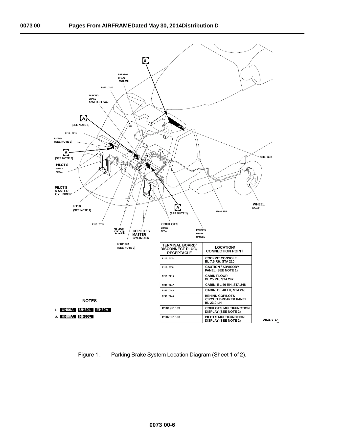
Parking brake troubleshooting in WP 0073 00 starts with circuit breakers on the upper console and copilot panel (CAUT/ADVSY PNL, LIGHTS ADVSY, LIGHTS CAUT/ADVSY), electrical power, and a firm-pedal checkout. If pedals bottom with no resistance, the flow checks lines for leaks and master-cylinder fluid level. When the parking brake handle is pulled with the tailwheel unlocked, the PARKING BRAKE ON capsule must illuminate, the handle must stay up, and the helicopter must not roll when the tail cone is pushed. Release is confirmed by a tap on the left brake pedal. Separate trees cover a dark PARKING BRAKE ON capsule (linkage, indicator lamp test, EMEP pin-filtered adapters P118 / P1019R / P1020R, 28 VDC at P118-H or P1019R-33 / P1020R-33, LIGHTS ADVSY breaker, continuity through switch S42) and brakes that do not hold (leaks, wear-indicator pin flush with the wheel-brake housing, pads versus parking-brake valve).
Tail wheel lock WP 0074 00 checks lockpin alignment, the miscellaneous switch panel TAIL WHEEL switch, and four mismatch cases: pin will not disengage while the switch reads LOCK, pin disengages but the switch still reads LOCK, pin will not engage while the switch reads UNLK, and pin engages but the switch still reads UNLK. Voltage is measured at P507-A/B/C and P135, continuity at J135 and J507, and actuator position (retracted or extended) is confirmed before linkage or lockpin replacement is called.
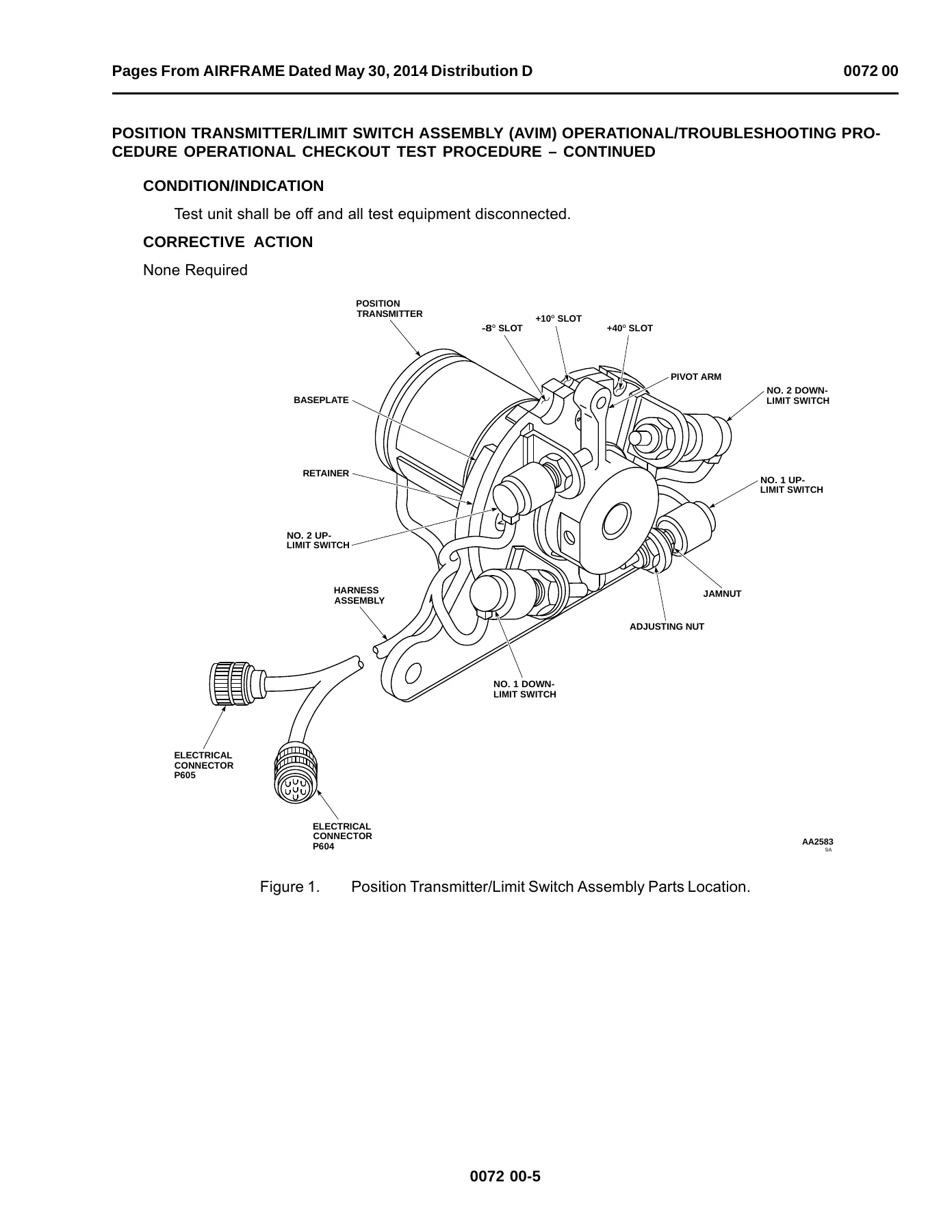
Stabilator position transmitter and limit-switch work at AVIM (WP 0072 00) is a bench checkout. The assembly is cleaned, inspected, and connected to a locally made test unit at P604/J604 and P605/J605 with stabilator indicators on P116 and P471R and an angle position indicator on the S1/S2/S3 and REF tipjacks. Pivot-arm travel must drive the indicators smoothly from -8° up to +40° down. Locked +10° down must read 350.5° to 352.5° on the API; transmitter nuts torque to 19–21 inch-pounds after adjustment. Up and down limit lamps (#1/#2 UP and #1/#2 DN) are set at the -8° and +40° slots, with API windows of 7°–9° and 300.5°–323.5° used to decide whether the baseplate or retainer must be replaced.
Engine Interface, Instruments, and Related Systems
Engine and engine interface WP 0075 00 isolates airframe causes first. A self-test BITE table on the torque meter maps 15% through 125% indications to DEC, Np demand, load share, TGT, alternator power, Ng, Np, torque, overspeed, hot-start prevention, 400 Hz power, collective channel, and Nr, sending the technician either into this volume (instrument display WP 0092 00, overspeed WP 0076 00, power WP 0106 00) or to TM 1-2840-248-23. A dedicated tree covers engine Ng low at ground idle. Companion packages then treat No. 1 and No. 2 engine instruments and warning lights, including the IVHMS variants; overspeed protection; speed trim; chip detector; anti-ice; start and ignition; and the engine controls quadrant at AVIM.
Rotor and drive coverage includes BIM indicators, AVIM main-rotor blade work, medium and high frequency vibration isolation, the gust lock, and transmission chip detector, instruments, and oil warning systems with a separate IVHMS package. Hydraulic systems occupy WP 0089 00. Pitot-static and pitot heater packages precede the instrument display system and its IVHMS counterpart.
Displays, Caution Panels, and AVIM Bench Units
Caution and advisory warning is written both in standard form and for UH-60A/UH-60L IVHMS. Digital clock checkout sits in WP 0094 00. Intermediate-level bench procedures then cover three central display unit part-number families (70450-01043-122; 1006448-10 or 1006448-30; and 70450-01043-125, 70450-21943-118, or 70450-01916-105), the pilots display unit, two signal data converter families, standard and LED caution/advisory panels, the chip detector resistor unit, and the miscellaneous switch panel. HH-60A and HH-60L MFD caution/advisory warning is isolated in WP 0104 00, matching the T6 legend-test step used when those aircraft are powered up for parking-brake checks.
Typical test equipment called in the initial-setup blocks includes multimeter AN/PSM-45A, angle position indicator 8810-F1110, stabilator indicators ID-2279/A, electrical repairer toolkit SC5180-99-B06, aircraft mechanic toolkit SC5180-99-B01, and a 0–30 in-lb torque wrench. Bench power for the position transmitter is specified as 27–28 VDC and 115 VAC, 400 Hz, single phase.
How the Procedures Are Built
Each work package follows the same technician-facing pattern: initial setup (test equipment, tools, personnel MOS where listed, references, equipment condition such as external power WP 1737 00 or APU per TM 1-1520-237-10), operational checkout with numbered steps, condition/indication statements, and corrective actions that branch to a named malfunction tree. Circuit-breaker pop-out is treated as a short and sent to WP 0108 00. Connector identifiers, pin letters, and schematic sheet numbers are printed in the trees so a meter lead can be placed without guessing. Location diagrams show cockpit, cabin station, tail cone, and relay-panel plugs; schematic sheets separate electrical, mechanical, and hydraulic lines.
This UH-60A UH-60L EH-60A HH-60A HH-60L Aviation Unit Intermediate Maintenance Troubleshooting Manual TM 1-1520-237-23-2 Volume 2 also carries metric conversion tables and DA Form 2028 / electronic 2028 instructions at the back of the file. Distribution Statement D and the Arms Export Control Act warning printed on the title page remain part of the document as published on 30 May 2014.
Use This Manual on the Aircraft
With this volume a unit or intermediate technician can run operational checkouts and isolate faults on the parking brake and tail-wheel lock, set and verify the stabilator position transmitter and limit switches, sort engine-interface BITE readings from airframe indicating faults, work engine instrument and warning-light paths including IVHMS, and bench-test display units, signal data converters, caution panels, and the miscellaneous switch panel. Correct torque (19–21 inch-pounds on transmitter and limit-switch hardware), API angle windows, 28 VDC pin checks, and the EDECU DAS-plug warning matter because the procedures are written around those values. Instant PDF delivery after payment — no shipping wait — so the file can be opened on any device and printed for the hangar or bench.

Reviews
There are no reviews yet.