
Mi-171Sh Helicopter Maintenance Manual Book III Part 2 Helicopter Systems 2011
Original price was: $39.95.$24.95Current price is: $24.95.
2011 Mi-171Sh Helicopter Maintenance Manual Book III Part 2 covering hydraulic power, ice and rain protection, landing gear, and pneumatic systems, with description, troubleshooting, maintenance practices, and storage guidance for ground servicing.
Description
File Details
- Manual type: Maintenance Manual (ground design description, servicing, troubleshooting, and maintenance practices)
- Aircraft: Mi-171Sh helicopter
- Volume: Book III, Part 2 — Helicopter Systems
- Document number: 171Sh.0000.00.MM
- Approval marking: 171Sh.0000.00. RE-LU
- Date: 2011 (effective pages dated March 31/11)
- Language: English
- Page count: 346
- File format: PDF
What This Volume Covers
The Mi-171Sh Helicopter Maintenance Manual Book III Part 2 Helicopter Systems 2011 is the Helicopter Systems volume of the composite Mi-171Sh Maintenance Manual. It is written for ground study of the airframe systems, component arrangement, and servicing of the helicopter on the ground. In-flight procedures belong in the Flight Manual. Check intervals and the list of scheduled operations belong in the Maintenance Schedule. Detailed task-card technology is held in the Task Card Collections, which this volume repeatedly cross-references.
Book III Part 2 itself is limited to four ATA-style sections: Hydraulic Power (029), Ice and Rain Protection (030), Landing Gear (032), and Pneumatic (036). The opening pages also map the rest of the full Maintenance Manual (Books 1–8 and the Task Card Collections) so the technician can see where this part sits, but those other books are not reproduced here.
Chapters Covered
- Introduction to the Maintenance Manual numbering system and topic page blocks (Description and Operation, Troubleshooting, Maintenance Practices, Storage, Transportation)
- Full MM book map: Book 1 General; Book 2 Airframe; Book 3 Helicopter Systems; Book 4 Power Plant; Book 5 Electronics; Book 6 Air Delivery Means; Book 7 Airborne Equipment; Book 8 armament-related sections; Task Card Collections 1–4
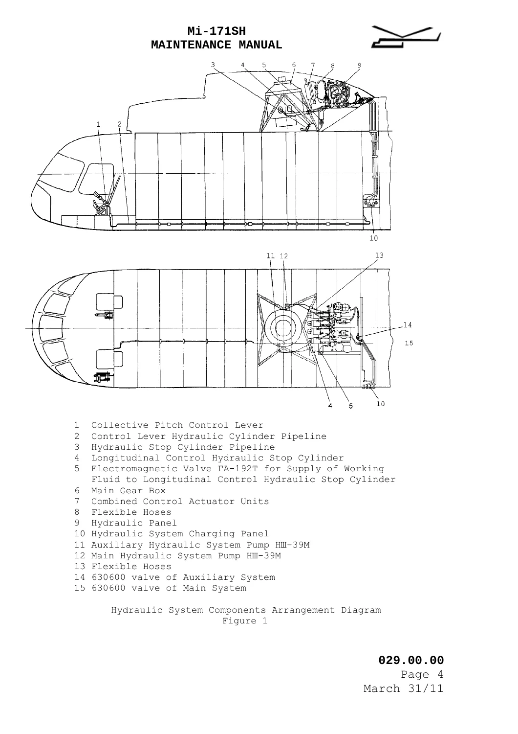
- 029.00.00 Hydraulic Power — General: purpose, main/auxiliary duplication, component arrangement, principal schematic, main technical data
- 029.10.00 Main Hydraulic System — Description and Operation (tank, НШ-39M pump, ГА-77B unloading valve, accumulators, filters, ГА-74M/5 and ГА-192 valves, manifolds, test panel)
- 029.10.00 Troubleshooting, Maintenance Practices, Storage
- 029.10.14 Shutoff Valve — Description and Operation
- 029.10.16 Servicing Panel — Description and Operation
- 029.20.00 Auxiliary Hydraulic System — Description and Operation, Troubleshooting, Maintenance Practices
- 029.30.00 Hydraulic Instruments — Description and Operation, Maintenance Practices
- 030.00.00 Ice and Rain Protection — General
- 030.20.00 Air Intake Anti-Icing System — Description and Operation, Maintenance Practices
- 030.40.00 Windshield Heating System — Description and Operation, Troubleshooting, Maintenance Practices
- 030.60.00 Rotor Anti-Icing System — Description and Operation, Maintenance Practices
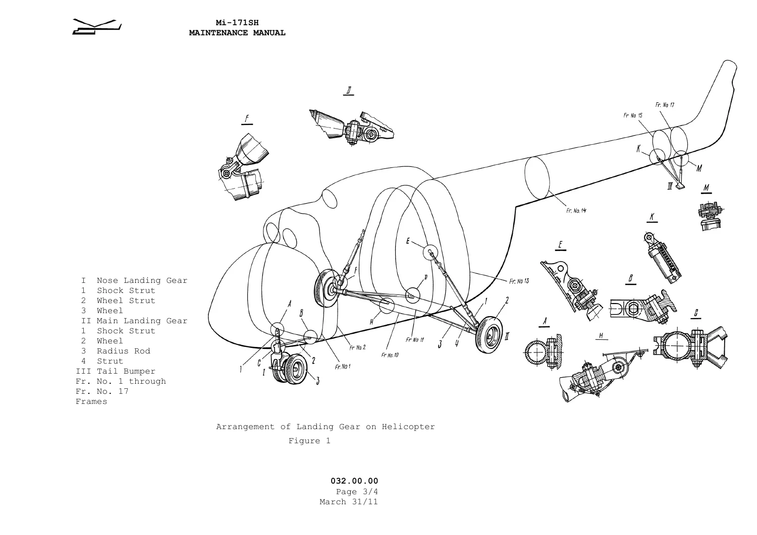
- 032.00.00 Landing Gear — General and arrangement
- 032.10.00 Main Landing Gear — Description and Operation, Troubleshooting, Maintenance Practices, Storage
- 032.20.00 Nose Landing Gear — Description and Operation, Troubleshooting, Maintenance Practices
- 032.40.00 Wheels and Brakes — Description and Operation, Troubleshooting, Maintenance Practices, Storage
- 032.70.00 Tail Bumper — Description and Operation, Troubleshooting, Maintenance Practices, Storage
- 036.00.00 Pneumatic System — General
- 036.10.00 Distribution and Sources of Compressed Air — Description and Operation, Troubleshooting, Maintenance Practices, Storage
- 036.20.00 Pneumatic Instruments — Description and Operation, Maintenance Practices
Taken together, the Mi-171Sh Helicopter Maintenance Manual Book III Part 2 Helicopter Systems 2011 gives a line technician the system theory, unit identities, pressure and capacity figures, leak and wear limits, removal/installation sequences, ground-test hook-up points, and storage/preservation steps needed to keep these four systems serviceable. It does not replace the Flight Manual, the Maintenance Schedule, or the Task Card Collections.
Hydraulic Power (Section 029)
The hydraulic system supplies oil АМГ-10 to the KAY-115AM combined actuators in the lateral, longitudinal, and collective-pitch control channels, plus the collective-lever friction-clutch cylinder and the longitudinal-control stop cylinder. Main and auxiliary circuits duplicate units and pipelines except for autopilot changeover of the combined control units and the clutch/stop cylinders, which work from the main system only.
НШ-39M gear pumps sit on main-gearbox drives so the system can still run if the engines fail and the main rotor windmills. The tank is partitioned into two chambers. Each circuit has a ГА-74M/5 two-position electromagnetic valve that connects pressure to the actuators; cutting off the main valve lets the auxiliary circuit be proved on its own, and energizing both valves lets the control kinematic chain be checked.
A ground test panel with four disconnect valves is fitted on the fuselage left side between frames 12 and 13 for an external hydraulic test set. Fluid is filled through the common tank filler or charged through a panel suction valve. Accumulators are charged with commercial nitrogen through cover valves using the airfield bottle and the gauge fixture from the helicopter ground-servicing set.
Printed main technical data include: working fluid АМГ-10; working pressure (4.5±0.3) to (6.5±0.8) MPa; ambient range −50 to +60 °C; fluid temperature up to 70 °C; system oil quantity 22 ltr; pump-on pressure (4.5±0.3) MPa; idle/return pressure (6.5±0.8) MPa; changeover to auxiliary at (3±0.5) MPa in the main system; accumulator nitrogen charge (3±0.2) MPa with no system pressure; filtering capacity 16 µm. Each tank half is filled with about 10 liters through the common neck. Accumulator capacity is given as 2.3 ltr. Filter 8Д2.966.017-2 is listed at 40 ltr/min maximum flow, working pressure up to (21+0.7) MPa, by-pass at (1.7+0.2) MPa, and 12 to 16 µm filtering. A note permits interchange of valves ГА192, ГА192T, ГА192T/2, and ГА192/1.
IMAGES PREVIEW
Maintenance practices in this section include checking the system from ground test set УПГ-250ТМ, pumping АМГ-10 through the circuit, washing filters ФГ-11БН and 8Д2.966.017-2, removing/installing accumulators, replacing the accumulator rubber membrane, assembling pipelines, and removing/installing the НШ-39M pump. Troubleshooting tables cover leaks, chafing, cracks, corrosion limits (including 0.2 mm on pipelines), hose outer-layer cracks, and loose unions.
Ice and Rain Protection (Section 030)
This section treats prevention and removal of ice and rain from main- and tail-rotor blades, the two flight-compartment windshields, and the air intakes, including dust-protection devices and engine nose sections. Rotor and windshield protection is electric. Dust-protection devices use both hot-air and electro-thermal heating; the engine nose section uses hot air bled from the engine compressors. Electric heating is supplied at 115/200 V, 400 Hz AC.
Ice onset is indicated by the CO-121 ice detector and a visual ice detector. Rotor and windshield systems can start automatically from the CO-121 signal or be selected manually. Dust-protection and engine heating are selected manually before flight; if they were left off, the circuit will still heat the RH engine and dust-protection device from the CO-121 signal. The section points the wiring schematic to Feeder 10-1 of the Wiring Diagram Manual and tells the reader to use, in addition to this book, the Maintenance Schedule, the ЭПК-2T electric-actuator manual, and the ПМК-21ТВ anti-icing-cycling timer-box manual.
Air-intake anti-icing combines compressor bleed through engine shutters 1919T (31/10 LH, 38/10 RH) with bonded heating plates on the dust-protection cowl, tail fairing, dust-outlet housing, bellmouth, and support-strut edges. The text quotes cowl plate resistances of (10.6+1.8) ohms, (10.6+1.8) ohms, and (5.6+1.0) ohms and ties the system to the HP-3BM fuel-control-pump thermal compensators of the TB3-117BT engines. Windshield heating and rotor anti-icing follow with their own description, operation, troubleshooting (windshield), and maintenance-practice pages.
Landing Gear (Section 032)
The landing gear is non-retractable and comprises a nose gear, two main gears, and a tail bumper, all with oleo-pneumatic shock struts charged with oil АМГ-10 and nitrogen. Printed dimensional data: track 4510 mm, wheelbase 4281 mm, static ground angle 4°35′, clearance along frame No. 14 of 185 mm. Main struts each carry one braked wheel; the nose gear carries two unbraked wheels. The tail bumper at the lower end of the tail boom protects the tail rotor and limits tail-boom g-load in a sharp pitch-up landing.
Nose wheels are K2116, 595×185, tire pressure 0.45+0.05 MPa. Main wheels are KT 97/3, 865×280, tire pressure 0.65+0.05 MPa, with air shoe brakes. Maintenance pages cover nitrogen pressure checks in the main shock struts, microswitch clearance, charging-valve replacement, removal and installation of main gear (helicopter on hydraulic jacks), nose- and main-wheel R&I, tire deflection, brake checks, and tire inflation. Troubleshooting sets dress limits of 0.1 mm for nicks and scratches on gear parts, corrosion limits, and paint restoration with enamel ЭП-140. Storage instructions preserve exposed fittings with grease ПВК (gun) or petrolatum and require wheel covers to keep oil, kerosene, and gasoline off the tires.
The tail-bumper subsection describes the shock strut, duralumin truss, and AK-6 stamped skid, with removal/installation task cards, oil change in the bumper shock strut, crack and weld inspection, and six-month preservation steps.
Pneumatic System (Section 036)
The air system brakes the main-gear wheels and can reinflate tire inner tubes from onboard bottles in off-field conditions. Two bottles totaling 10 ltr, formed by the inner chambers of the main-gear struts, are charged to 4 to 5+0.4 MPa. In flight the system is charged by piston compressor АК-50T1 on the main gearbox; on the ground it is charged through helicopter charging valve 3509C50 from a ground bottle.
Units include gravity filter, air filters 723900-4АТ and 723900-6АТ, pressure control unit АД-50, reducing valve УП25/2, pneumatically controlled reducing valve УП03/2М, check valve 636100M, and charging valve 800600-1. The pneumatic panel sits on the cargo-compartment left side between frames 11 and 12. Pipelines are painted black with enamel ЭП-140. Instruments МВУ-100K (bottle pressure 4 to 5+0.4 MPa) and МА-60 (brake pressure) are on the pilot’s left electric panel.
Maintenance practices cover condensate drain from the gravity filter and bottles, unit and pipeline condition checks, charging checks, brake-system leak checks, and filter washing. Troubleshooting warns to relieve system pressure before replacing pipelines and to locate brake leaks against the BRAKE (ТОРМОЗ) gauge on the pneumatic panel.
How the Manual Is Organized for Shop Use
Every section follows the same topic-page blocks used across the Mi-171Sh MM: Description and Operation, Troubleshooting (page block 101), Maintenance Practices including adjustments, tests, inspections, and removal/installation (page blocks 201–500), Storage (901), and Transportation where used. Item numbering is section.subsection.subject (example given in the introduction: 029.10.01 Hydraulic Tank). Since 2007 the helicopter itself is identified by a sixteen-character code such as 171Sh00604105308U; operational paperwork uses the last five characters (for example 5308U).
Many procedures in this PDF are listed as task-card numbers (029.10.00F through 029.10.00k, 032.10.00C through 032.70.00d, 036.10.00A through 036.10.00F, and so on) that point into Collection 1 or Collection 2. Buyers who need the full step-by-step cards will also need those collections and the Maintenance Schedule. This volume still supplies the system description, limits, component lists, figures, and a large number of embedded removal, installation, inspection, and storage procedures.
Use This Manual for Ground Work on These Systems
With the Mi-171Sh Helicopter Maintenance Manual Book III Part 2 Helicopter Systems 2011 a technician can study how the duplicated hydraulic circuits feed the KAY-115AM actuators, prove main versus auxiliary supply, charge accumulators with nitrogen, hook a ground hydraulic cart to the frame 12–13 test panel, wash and replace filters, change accumulator membranes, and restore pipelines within the printed corrosion and damage limits. The same book supports ice-protection work on intakes, windshields, and rotors; oleo charging, wheel and brake R&I, and tail-bumper service; and pneumatic charging, condensate drain, and brake-leak diagnosis.
Using the printed pressures, capacities, and damage limits matters because the control actuators, shock struts, and wheel brakes share АМГ-10, nitrogen, and compressed air across tightly specified bands. Working outside those figures, or mixing main-only functions onto the auxiliary circuit, is exactly what the changeover and unloading-valve descriptions are written to prevent.
Delivery is an instant PDF download after purchase — no shipping wait, readable on any device, and printable for the hangar or line box. This listing is Book III Part 2 only; pair it with the Flight Manual, Maintenance Schedule, and Task Card Collections when the job requires those documents.
Reviews
There are no reviews yet.