
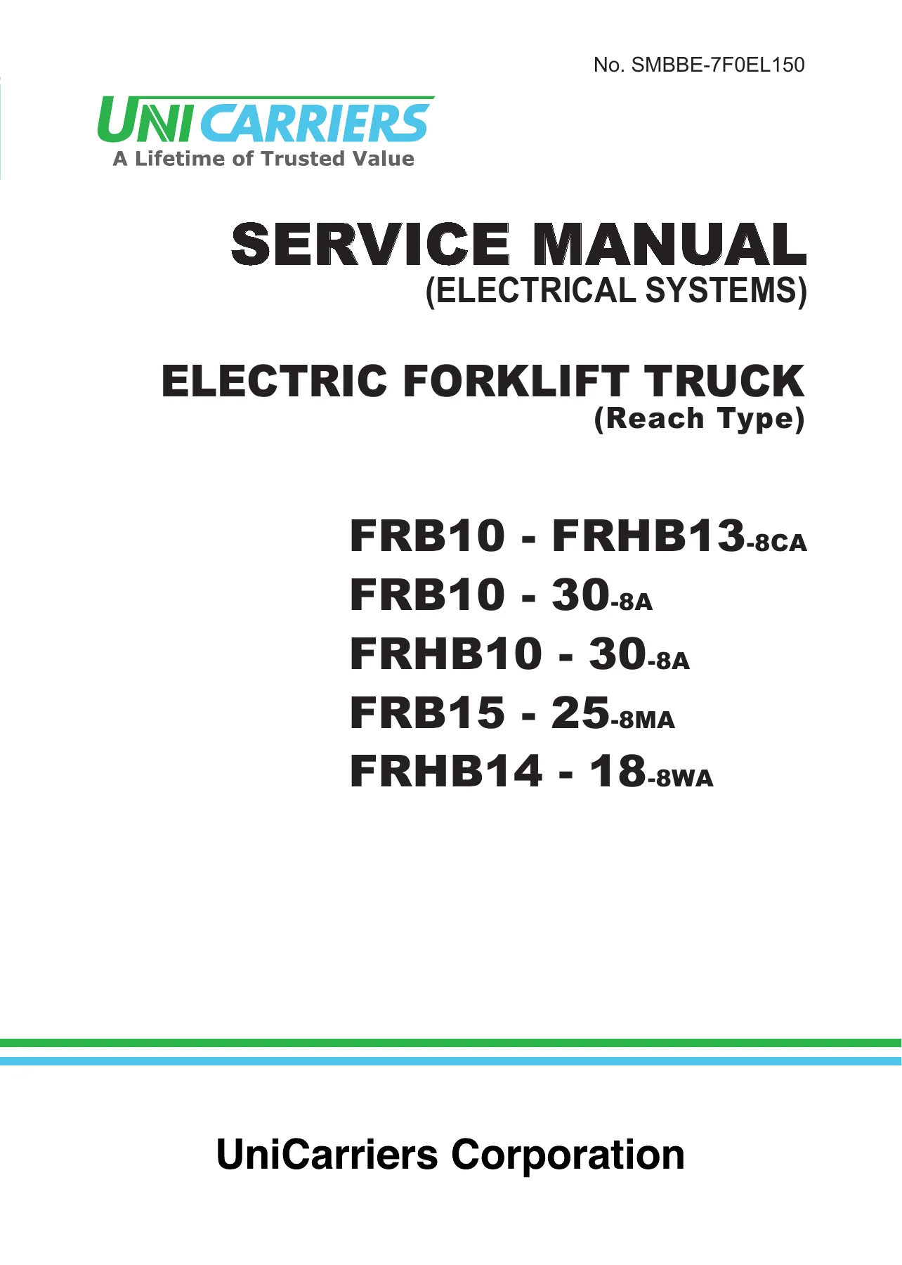
UniCarriers FRB/FRHB-8 Series Electric Reach Forklift Truck Electrical Systems Service Manual – PDF Download
Original price was: $44.95.$29.95Current price is: $29.95.
Complete electrical systems service manual for UniCarriers FRB and FRHB-8 series electric reach forklift trucks. 184 pages of troubleshooting, wiring diagrams, battery/charger service, and component inspection procedures. Instant PDF download.
Description
UniCarriers FRB/FRHB-8 Series Electric Forklift Truck Electrical Systems Service Manual
This UniCarriers FRB/FRHB-8 Series Electric Forklift Truck Electrical Systems Service Manual is the complete electrical systems service and repair guide for the FRB and FRHB-8 series battery-powered reach forklift trucks. Covering everything from the main controller and EPS controller to the battery charger, motors, sensors, and the complete vehicle wiring harness, this manual gives technicians and fleet maintenance personnel the exact procedures, specifications, and wiring diagrams needed to diagnose faults, perform repairs, and keep these electric reach trucks operating reliably.
File Details
- Manual Type: Electrical Systems Service Manual
- Brand: UniCarriers
- Equipment Type: Electric Forklift Truck (Reach Type)
- Series: FRB-8 / FRHB-8
- Document Number: SMBBE-7F0EL150
- Language: English
- Page Count: 184
- File Format: PDF
- Publication Date: January 2015
Chapters Covered
- 1. Control System
- 2. Troubleshooting Guide
- 3. Battery and Battery Charger
- 4. Inspection of Major Electric Components
- 5. System Wiring Diagram
- 6. Wiring Connection Diagram
- 7. General Wiring Diagram
1. Control System
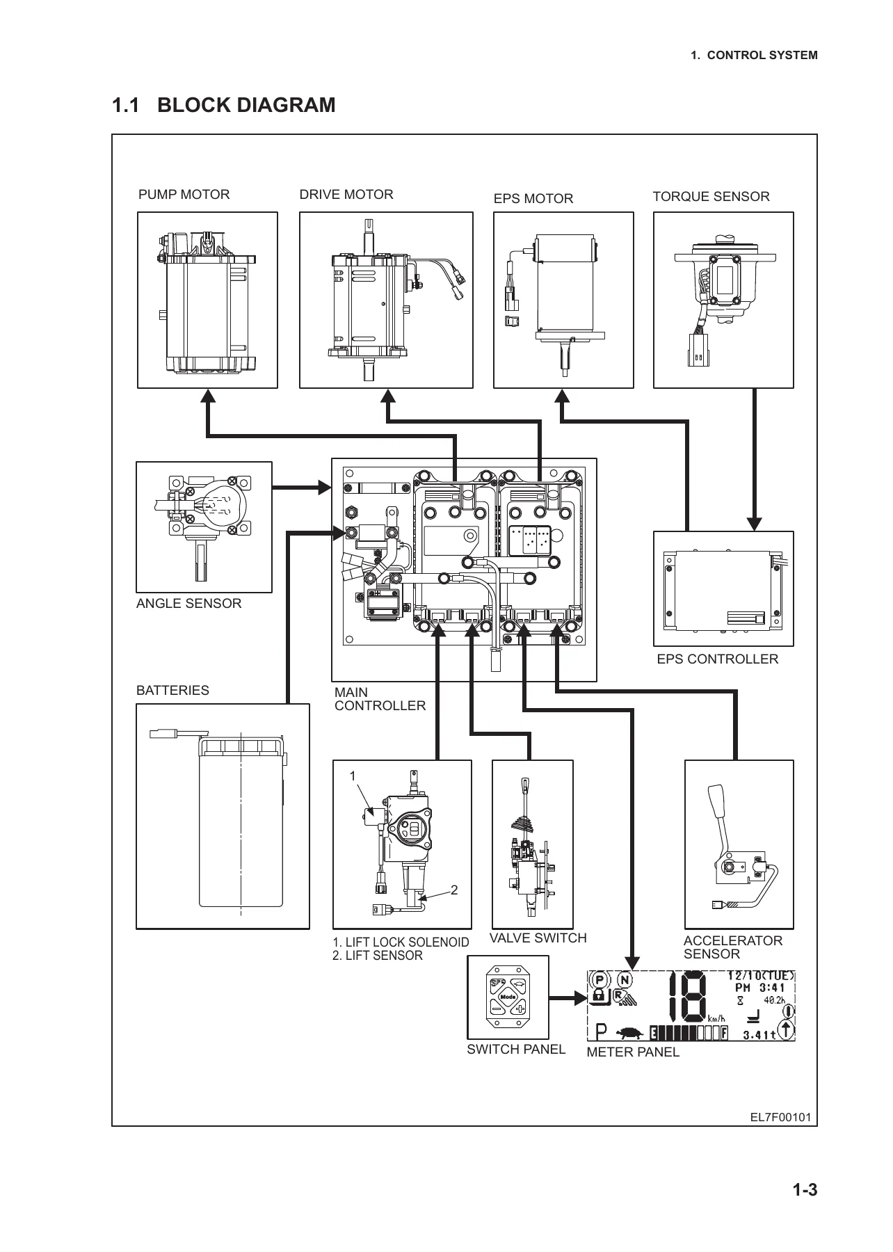
The control system chapter opens with a full block diagram of the truck’s electrical architecture and a general description of truck control — covering battery connection, key switch operation, travel speed control, lifting speed control, and steering control. It then provides the main controller’s leading particulars, general description, and maintenance procedures, followed by the EPS controller’s general description and maintenance. The meter panel section covers the main screen, charger screen, maintenance (monitor) screen, error list screen, and parameter setting. Detailed connector arrangements with terminal-by-terminal pinout tables are included for CN1D, CN2D, CN1P, CN2P, and CN1E, making it straightforward to trace signals and identify wire colours.
2. Troubleshooting Guide
This chapter is built around the error codes the truck’s meter panel and controllers can display. It begins with meter panel system errors and their internal codes, then lists every truck error code with probable cause, action required, and remarks. A separate section covers failure phenomena that occur without error codes — nothing displayed on the meter panel, MD contactor issues affecting travel/load handling/steering, travel system faults, load handling problems (lift, tilt, reach), load handling operation, and hard steering. Each flow chart walks through voltage measurements, continuity tests, and component-level decisions in a logical sequence, so you can pinpoint the fault without guesswork.
3. Battery and Battery Charger
This chapter covers both the battery pack and the on-board battery charger in detail. Battery topics include leading particulars, general description, maintenance procedures (electrolyte inspection, specific gravity measurement, leakage testing, cleaning, water addition, storage), and a trouble diagnosis table with corrective actions for short circuits, sulfation, excessive self-discharging, and polarity exchange. The on-board charger section covers its construction, operation and inspection procedures for normal charging, equalizing charge, super equalizing charge, preset charging (start/end at specified date and time), auxiliary charging, and charging before long-term storage. Maintenance procedures for the CM contactor, charger switch panel, transformer, power supply tap changing, and charger adjustment are all included.
4. Inspection of Major Electric Components
This chapter provides removal, reinstallation, inspection, and troubleshooting procedures for the major electric components on the truck. It covers the drive motor, pump motor, and EPS motor — including insulating resistance measurement, thermo-sensor checking, rotation sensor testing, and a drive/pump motor troubleshooting guide. It then covers the other electric components: fuses F4, F5, F8, F9, accelerator, angle sensor, torque sensor, lift sensor, lift lock solenoid, keypad switches, brake switch, floor switch, battery lock switch, key switch, lighting switch, turn signal switch, horn switch, headlight, turn signal light, back-up buzzer, valve switch, PO relay, BB relay and optional relays, and the 4-way detection switch. Each component section includes the relevant inspection criteria, resistance values, and adjustment procedures.
5. System Wiring Diagram
The system wiring diagrams are broken down by subsystem — power supply and charging, auxiliary (lighting) system, operation and control (meter panel), drive system, load handling system, steering system (power steering), and 4-way trucks. Each diagram uses colour coding for earth, power supply, and signal lines, making it easy to trace circuits and understand how each subsystem connects to the controllers and meter panel.
6. Wiring Connection Diagram
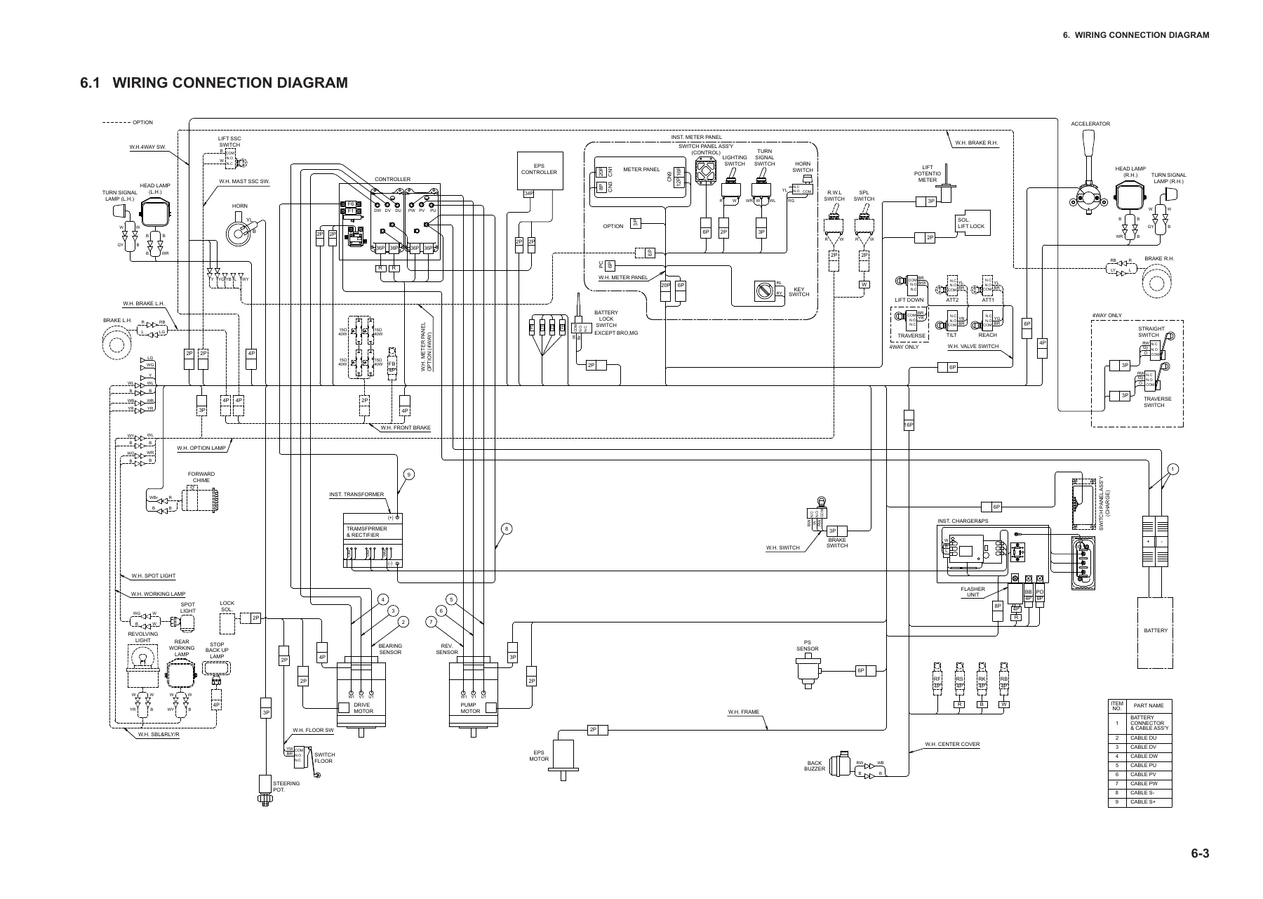
This chapter provides a comprehensive wiring connection diagram showing all major components, harness routing, connector locations, and pin assignments across the entire truck. It is an invaluable reference for identifying wire colours, connector types, and the physical layout of the electrical system.
7. General Wiring Diagram
The general wiring diagram consolidates the complete electrical system into a single overall reference, showing the interconnections between all controllers, motors, sensors, switches, relays, lights, and the battery. This is the diagram you keep open when you need to understand the big picture or trace a circuit from one end of the truck to the other.
Take Control of Your Truck’s Electrical System
With this UniCarriers FRB/FRHB-8 Series Electrical Systems Service Manual in hand, you can confidently tackle the electrical faults that stop these reach trucks in their tracks. Whether you are a fleet maintenance technician, an independent forklift mechanic, or a facility manager responsible for keeping material handling equipment running, this manual gives you the same level of detailed guidance the professionals rely on.
From interpreting error codes and tracing wiring faults to testing sensors, servicing the battery charger, and replacing the main controller, every procedure is laid out with the measurements, values, and diagrams you need. The wiring diagrams alone are worth the price — they turn a frustrating electrical gremlin into a systematic diagnosis.
IMAGES PREVIEW
This is a digital PDF download, delivered instantly to your device after purchase. There is no shipping, no waiting, and no physical book to misplace. Keep it on your laptop, tablet, or phone in the workshop, or print the pages you need for the job at hand. The PDF is fully readable on any device and ready to go the moment your payment is processed.
Reviews
There are no reviews yet.