Videojet Labeljet 210 Label Applicator Service Manual Complete PDF
Original price was: $95.00.$16.95Current price is: $16.95.
Official Videojet factory service manual for the Labeljet 210 automatic label applicator system. Complete 142-page technical documentation covering installation procedures, web drive mechanism, stepper motor control, electronics module, CPU circuit diagrams, sensor calibration, mechanical assembly, troubleshooting protocols, component replacement, and preventive maintenance. Essential service manual for packaging line technicians, automation engineers, and authorized label applicator service personnel.
Description
Videojet Labeljet 210 Label Applicator Service Manual Complete PDF DOWNLOAD
DESCRIPTION
Videojet Labeljet 210 Label Applicator – Official Factory Service Manual
This is the complete, official Videojet Technologies factory service manual for the Labeljet 210 automatic label applicator system. With 142 comprehensive pages of detailed technical information, this manual provides everything needed for professional installation, calibration, repair, and troubleshooting of these high-speed label applicators used on production and packaging lines worldwide.
FILE DETAILS
- Part Number: P/N 361627-01
- Equipment: Labeljet 210 Label Applicator
- Manufacturer: Videojet Technologies Inc.
- Revision: AA, August 2006
- PDF Quality: High-quality optimized professional documentation
- Total Pages: 142 Pages
- File Size: 5.8 MB
- Format: Letter size (8.5″ x 11″)
- Classification: Confidential Technical Manual – Trained Service Personnel Only
APPLICATOR SPECIFICATIONS
Physical Specifications:
- Weight: 23 kg (50.7 lbs)
- Compact design for integration into production lines
- Flexible mounting options (top, side, or bottom label application)
Operational Capabilities:
- High-speed automatic label dispensing
- Precision label placement
- Web tension control
- Multiple label size compatibility
- Synchronization with production line speed
Mounting Options:
- Floor-mounted stand configurations
- “U” arm mounting bracket (standard)
- Adjustable positioning for optimal label placement
- Parallel chassis orientation to product surface
Environmental Compliance:
- FCC Compliance: Class A digital device (USA)
- Canadian Compliance: Radio Interference Regulations
- CE Mark: European Union conformance
- UL Listed for safety standards
Power Requirements:
- Voltage selector for multiple regions
- Mains fuse protection
- On/Off power switch with indicator
- Toroidal transformer for stable operation
COMPREHENSIVE MANUAL COVERAGE
CHAPTER 1: INTRODUCTION
- About the Service Manual:
- Purpose and scope for trained service personnel
- Manual organization and navigation
- Chapter-by-chapter overview
- Index for quick reference
- Related Documents:
- Labeljet 210 Operator Manual (P/N 361626-01)
- Cross-reference guide
- Language Codes:
- 23 available language versions
- Language code ordering system
- Availability indicators for Operator Manual, Service Manual, and Parts Breakdown
- Hazard Information:
- General Warning Notices:
- Lethal hazard from mains electrical supply
- Trained personnel requirement for installation
- Personal injury from exposed rotating parts
- Weight-related lifting hazards (23 kg)
- General Caution Notices:
- Equipment damage prevention
- ESD (Electrostatic Discharge) precautions
- Proper handling procedures
- General Warning Notices:
- Abbreviations Used:
- Technical terminology reference
- Standard industry abbreviations
- Conventions for Figures and Tables:
- Diagram numbering system
- Table formatting standards
- Reference notation
CHAPTER 2: INSTALLATION
- Installation Safety:
- Mains disconnection requirements
- Trained personnel restrictions
- Rotating parts warnings
- Lifting equipment requirements
- Production line variation considerations
- Mounting the Labeljet 210:
- Mounting stand positioning
- “U” arm mounting bracket installation
- Chassis parallel alignment procedures
- Peel tip positioning (minimum gap to product)
- Mounting bolt tightening sequence
- Top, side, or bottom application configurations
- Assembling Components:
- Operator Control Panel (OCP) and Mounting Tube:
- Tube fitting to chassis clamp
- Position adjustment procedures
- Clamp tightening verification
- 8-pin DIN cable connection
- Label Sensor:
- Calibration Procedures:
- Digital voltmeter (DVM) requirements
- Potentiometer adjusting tool
- ESD precautions during calibration
- CPU PCB access procedures
- RV2 adjustment to 3.45-3.48 volts
- Test Point 1 (TP1) voltage measurement
- 270-degree potentiometer arc limitations
- Assembly:
- Mounting shaft installation
- Center positioning on label width
- Locking screw tightening
- 6-way Amphenol connection
- Calibration Procedures:
- Wipe-down Brush:
- Bracket mounting
- Angle and position adjustment
- Light contact verification with product
- Unwind Reel Flanges:
- Inner flange identification (steel socket headed grubscrew)
- Outer flange identification (nylon grubscrew)
- Shaft flat portion alignment
- Web centering on drive rollers
- Grubscrew tightening procedures
- Product Detector:
- Conveyor-side installation
- 4-way Amphenol connection to connector panel
- Label Roll:
- Loading Procedures:
- Power disconnection safety
- Core fitting on inner flange hub
- Outer flange locking mechanism
- Threading the Label Web:
- 800mm web pull requirement
- Drive roller and nip roller separation
- Cranked nip arm operation
- Rewind reel lock pin procedures
- Two-three wrap securing method
- Friction block and peel plate path
- Label sensor slot threading
- Loading Procedures:
- Shaft Encoder:
- 4-pin DIN connector installation
- Speed synchronization setup
- Pinout interface details
- Operator Control Panel (OCP) and Mounting Tube:
- Setting up the Machine:
- Aligning the Label Web:
- Inboard and outboard web guide collar positioning
- Manual rewind reel rotation
- Web centering on drive rollers
- 500mm settling cycle
- 1mm guide collar gap specification
- Label sensor positioning and thumb knob adjustment
- 180-degree sensor rotation for narrow webs
- Setting up Password Levels:
- Password Level 1: Read-only operator access
- Password Level 2: Full modification access
- Security configuration
- Connecting the Machine’s Mains Supply:
- Voltage selector verification
- Fuse rating confirmation
- Grounding requirements
- Setting up the Engineering Menu:
- System parameter configuration
- Factory default settings
- Calibration constants
- Setting up the Operator Controls:
- LCD display configuration
- Increment/decrement key functions
- Indicator LED setup (Machine On, Product Detect, Label Out)
- Adjusting the Web Tension and Product Detector:
- Dancer arm tension optimization
- Product detection sensitivity
- Trigger point calibration
- Aligning the Label Web:
CHAPTER 3: MACHINE DESCRIPTION
- Web Drive Mechanism:
- Stepper Motor:
- Motor specifications and ratings
- Step resolution
- Torque characteristics
- Driver circuit operation
- Control signals
- Web Drive:
- Drive roller specifications
- Nip roller pressure system
- Cranked nip arm mechanism
- Belt drive system
- Gear ratio calculations
- Unwind and Rewind Reel:
- Passive unwind system
- Active rewind mechanism
- Brake band operation
- Tension control
- Friction Block:
- Peel plate interaction
- Label separation mechanism
- Pressure adjustment
- Stepper Motor:
- Electronics Module:
- Connector Panel:
- Product detector plug
- Label sensor plug (6-way Amphenol)
- Shaft encoder connector (4-pin DIN)
- Mains inlet connector
- Mains fuse holder
- Mains on/off switch
- Mains voltage selector
- Control panel connector (8-pin DIN)
- Lamp stack connector
- General alarm connector
- CPU PCB (5-Sheet Circuit Diagram):
- Foldout 1: Microprocessor and memory circuits
- Foldout 2: Power supply regulation
- Foldout 3: Motor driver circuits
- Foldout 4: Sensor input conditioning
- Foldout 5: Output drivers and interfaces
- Component locations
- Test points (TP1, TP2, etc.)
- Adjustment potentiometers (RV1, RV2)
- Fuse locations (Fuse 2)
- Capacitor C19 and C20 positions
- Toroidal Transformer:
- Primary and secondary winding specifications
- Voltage ratings
- Current capacity
- Mounting details
- Connector Panel:
- Sensors and Actuators:
- Label Sensor:
- Optical detection principle
- Reflective/transparent label detection
- Gap/mark sensing capability
- Calibration procedures
- RV2 potentiometer adjustment
- Product Detector:
- Photo-electric sensor operation
- Sensing range specifications
- Response time
- Mounting options
- Label Low Microswitch:
- Roll diameter monitoring
- Low label warning activation
- Contact specifications
- Encoder:
- Incremental encoder type
- Pulse resolution
- Speed measurement
- Synchronization signals
- Label Sensor:
- Mains Input and DC Power Supplies:
- Voltage input specifications
- Rectification circuits
- DC regulation systems
- Protection circuits
- Power distribution
- Control Panel:
- Foldout 6: Control Panel PCB Circuit Diagram
- LCD display driver circuits
- Keypad matrix
- LED indicator drivers
- Microcontroller interface
- Functional Description:
- LCD menu navigation
- Increment/decrement key operation
- Indicator functions
- Password access levels
- Interface between Control Panel and Electronics Module:
- 8-pin DIN serial communication
- Signal descriptions
- Pinout details
- Foldout 6: Control Panel PCB Circuit Diagram
CHAPTER 4: CLEANING AND MAINTENANCE
- Cleaning the Web Path:
- Drive roller cleaning procedures
- Nip roller maintenance
- Peel plate cleaning
- Friction block maintenance
- Label sensor optical surface cleaning
- Recommended cleaning agents
- Cleaning frequency schedules
- Inspecting the Connections and Fittings:
- Connector panel inspection
- Cable integrity verification
- Connector pin condition
- Ground continuity checks
- Mounting bolt torque verification
CHAPTER 5: TROUBLESHOOTING
- Machine Problems:
- Power supply failures
- Control system faults
- Communication errors
- Sensor malfunctions
- Motor drive problems
- Display issues
- Label Problems:
- Breaking:
- Excessive web tension
- Drive roller pressure too high
- Label material defects
- Incorrect threading
- Slipping:
- Insufficient web tension
- Drive roller contamination
- Worn drive roller surface
- Nip roller pressure too low
- Dispensing:
- Peel plate angle incorrect
- Friction block position
- Label adhesion issues
- Air blast timing
- Advancing:
- Stepper motor stalling
- Belt tension problems
- Encoder signal errors
- Timing issues
- Positioning:
- Product detector misalignment
- Encoder calibration errors
- Speed synchronization problems
- Label sensor positioning
- Applying:
- Wipe-down brush angle
- Product surface condition
- Label adhesive quality
- Application speed
- Rewinding:
- Rewind tension too tight/loose
- Brake band adjustment
- Lock pin engagement
- Belt slippage
- Breaking:
- Password Problems:
- Password reset procedures
- Access level restoration
- Factory default recovery
- Adjustment and Repairs:
- Adjusting the Hold-down Spring:
- Spring tension verification
- Adjustment procedures
- Performance testing
- Inspecting the Connector Panel:
- Visual inspection procedures
- Contact cleaning
- Pin straightening
- Adjusting the Dancer Arm Tension:
- Tension spring adjustment
- Optimal tension settings
- Performance verification
- Adjusting the Rewind Reel Drive Belt:
- Belt tension measurement
- Adjustment procedures
- Belt replacement criteria
- Resetting Passwords:
- Service-level password reset
- Default password restoration
- Access level configuration
- Checking the Control Panel Cable:
- Continuity testing
- Pin-to-pin verification
- Connector integrity
- Adjusting the Hold-down Spring:
- Replacing Faulty Components:
- Product Detector:
- Removal procedures
- Mounting bracket service
- Cable routing
- Installation and alignment
- Label Sensor:
- Disassembly procedures
- Calibration requirements
- Installation procedures
- Control Panel PCB:
- PCB removal from housing
- LCD disconnection
- Keypad removal
- New PCB installation
- Functional testing
- CPU PCB:
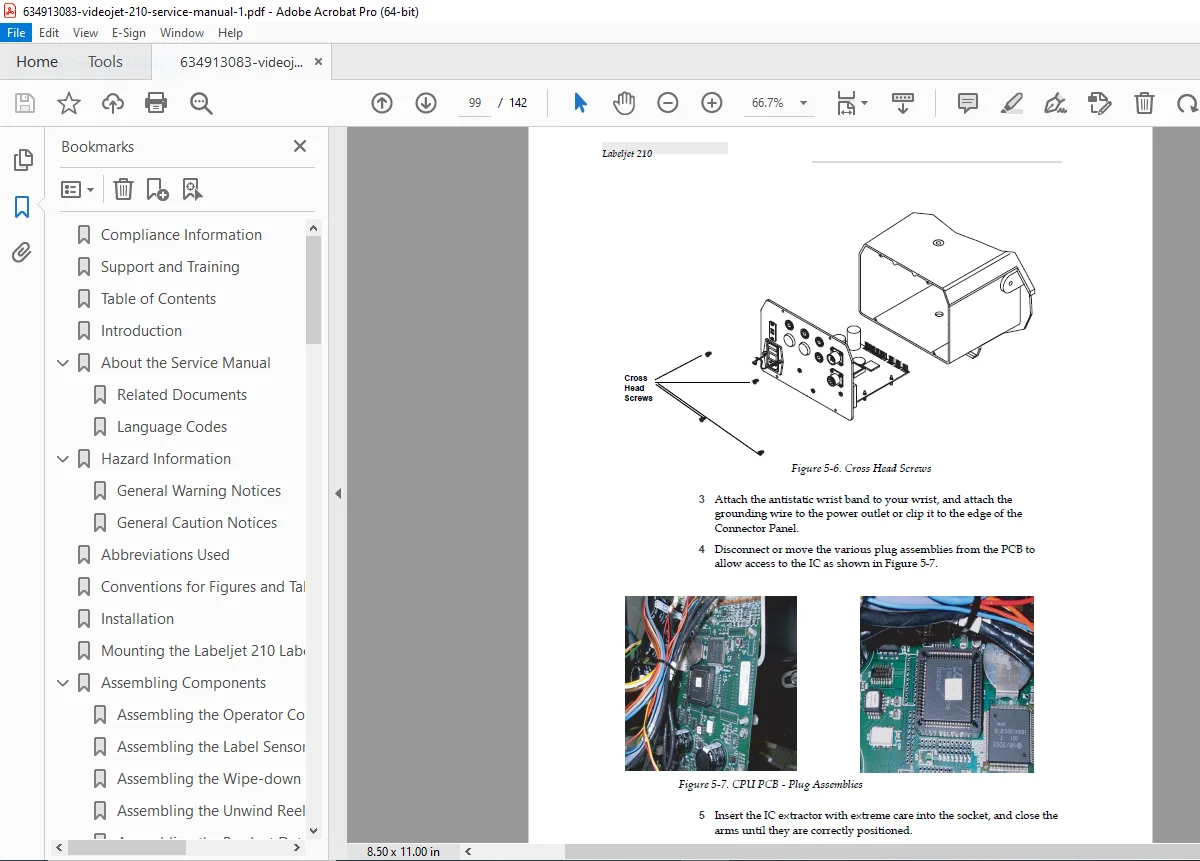
- Connector panel disassembly
- All connector disconnection
- Mounting screw removal
- New board installation
- Recalibration requirements
- Toroidal Transformer:
- Power disconnection verification
- Mounting bracket removal
- Primary/secondary disconnection
- New transformer installation
- Drive Belt:
- Tension release procedures
- Belt removal sequence
- New belt installation
- Tension adjustment
- Brake Band:
- Band tension release
- Mounting screw removal
- New band installation
- Tension setting
- Stepper Motor:
- Drive belt removal
- Electrical disconnection
- Mounting bracket removal
- Motor replacement
- Belt reinstallation
- Drive Roller:
- Nip roller retraction
- End cap removal
- Roller extraction
- New roller installation
- Mains Input Module:
- Power disconnection
- Connector removal
- Module extraction
- New module installation
- Fuse 2 on CPU PCB:
- PCB access procedures
- Fuse identification
- Replacement procedures
- Cause investigation
- Capacitors C19 and C20:
- Component location
- Desoldering procedures
- Polarity verification
- New capacitor installation
- Mains Input Fuse:
- Fuse drawer access
- Fuse rating verification
- Replacement procedures
- Product Detector:
CHAPTER 6: CONSUMABLES AND OPTIONS
- Consumables:
- Label rolls (various sizes and materials)
- Cleaning supplies
- Replacement parts with wear characteristics
- Options:
- Shaft encoder for line synchronization
- Lamp stack for visual status indication
- General alarm output
- Custom mounting brackets
- Special label sensor configurations
APPENDIX A: APPLICATOR SPECIFICATIONS
- Complete technical specifications
- Performance parameters
- Environmental ratings
- Electrical characteristics
- Mechanical dimensions
- Compliance certifications
APPENDIX B: ILLUSTRATED PARTS LIST
- How to Use this Parts List:
- Part numbering system
- Exploded view diagrams
- Item reference numbers
- Major Assembly Diagrams:
- Labeljet 210 Major Assemblies:
- Overall system overview
- Subassembly identification
- Operator Control Panel:
- LCD display assembly
- Keypad components
- PCB and connectors
- Mounting hardware
- Foldout 7: Web Drive Components:
- Drive roller assembly
- Stepper motor mounting
- Belt drive system
- Nip roller mechanism
- Bearing locations
- Web Drive Components (Detailed):
- Individual part callouts
- Part numbers and descriptions
- Quantity per assembly
- Electronic Components and Mounting Bracket:
- CPU PCB mounting
- Transformer location
- Connector panel assembly
- Cable routing
- Electronics Module:
- Complete electronics assembly
- PCB interconnections
- Power distribution
- Sensor interfaces
- Labeljet 210 Major Assemblies:
INDEX:
- Comprehensive alphabetical subject index
- Cross-referenced topics
- Page number references
- Quick-lookup functionality
TECHNICAL HIGHLIGHTS
Stepper Motor Control:
- Precision positioning for label dispensing
- Variable speed control
- Microstepping capability
- Stall detection and protection
Web Handling System:
- Active drive with passive unwind
- Constant tension control via dancer arm
- Automatic label detection
- Precise peel and dispense mechanism
Electronics Architecture:
- Microprocessor-based control
- Real-time sensor monitoring
- Programmable operating parameters
- Serial communication with control panel
Safety Features:
- Multiple interlocks for operator protection
- Rotating parts guarding
- Electrical isolation
- Thermal protection
REGULATORY COMPLIANCE
United States:
- FCC Part 15 Class A compliance
- Radio frequency interference limits
- Shielded cable requirements
- UL Listed safety certification
Canada:
- Canadian Radio Interference Regulations compliance
- CSA certification
- Bilingual labeling requirements
European Union:
- CE marking for EU conformance
- Low Voltage Directive
- EMC Directive compliance
WARRANTY & SERVICE
Total Source® Service Program:
- Applications support
- Installation services
- Maintenance training
- Customer response center
- Technical support hotline
- Field service availability
- Extended hours phone assistance
- Parts and supplies distribution
- Repair service network
Customer Training:
- Factory-authorized training courses recommended
- Hands-on equipment familiarization
- Troubleshooting techniques
- Preventive maintenance procedures
- Service certification programs
Service Manual Disclaimer:
- Intended as supplement to (not replacement for) training
- Hands-on training highly recommended
- Contact Videojet at 1-800-843-3610 (US) for training information
CONTACT INFORMATION
Videojet Technologies Inc. (USA):
- Address: 1500 Mittel Boulevard, Wood Dale, IL 60191-1073
- Phone: 1-800-843-3610
- Fax: 1-800-582-1343
- International Fax: 630-616-3629
International Offices:
- USA: Atlanta, Chicago
- International: Canada, France, Germany, Ireland, Japan, Spain, Singapore, The Netherlands, United Kingdom
- Worldwide distributor network
IDEAL FOR:
- Packaging line maintenance technicians
- Production automation engineers
- Videojet authorized service centers
- Independent packaging equipment technicians
- Manufacturing facility technical staff
- Contract packaging service companies
- Production line supervisors with technical responsibilities
- Automation system integrators
- Food and beverage packaging technicians
- Pharmaceutical packaging equipment specialists
- Consumer goods manufacturing technical staff
WHY THIS MANUAL IS ESSENTIAL:
The Labeljet 210 is a precision label applicator used in high-speed production environments. This comprehensive 142-page service manual provides:
✓ Installation Expertise – Complete mounting and assembly procedures
✓ Sensor Calibration – Precise label sensor voltage adjustment (3.45-3.48V)
✓ Circuit Diagrams – 5-sheet CPU PCB foldout schematics
✓ Troubleshooting Guide – Systematic problem diagnosis for label issues
✓ Component Replacement – Step-by-step procedures for all major parts
✓ Web Path Optimization – Proper threading and tension adjustment
✓ Illustrated Parts List – Exploded diagrams with part numbers
✓ Safety Compliance – FCC, CE, UL certification requirements
IMPORTANT SERVICE NOTICE:
This service manual is intended for use by trained Videojet service personnel and qualified packaging equipment technicians only. Servicing label applicators requires:
- Understanding of stepper motor control systems
- Knowledge of web handling and tension control
- Familiarity with optical sensor calibration
- Proper ESD protection when handling electronics
- Appropriate tools including digital voltmeters
- Understanding of production line integration
- Safety awareness of rotating machinery hazards
WARNING: Improper service can result in:
- Equipment damage or malfunction during production
- Personal injury from rotating parts (exposed mechanisms)
- Electrical shock hazards (lethal voltage present)
- Improper label application affecting product identification
- Production line downtime and lost productivity
- Voided warranty and compliance certifications
Always:
- Disconnect mains power before servicing
- Follow ESD precautions when handling CPU PCB
- Use proper lifting equipment (23 kg weight)
- Verify all safety interlocks after service
- Test operation before returning to production
- Keep hands and clothing away from rotating parts
Keep your Videojet Labeljet 210 applicator running at peak efficiency! This official factory service manual provides the same comprehensive information used by Videojet-trained technicians. With instant PDF download, qualified packaging equipment technicians can access this 142-page technical resource immediately. Whether performing routine maintenance, calibrating label sensors, troubleshooting web handling issues, or replacing motors and electronics, this manual is your complete technical reference for professional label applicator service.