
Vögele SUPER 1600-2 & 1800-2 Paver Machine Technology Training Manual – PDF
Original price was: $54.95.$34.95Current price is: $34.95.
Complete Vögele machine technology training manual for the SUPER 1600-2 and SUPER 1800-2 pavers. Covers hydraulic systems, electrical architecture, CAN bus control technology, Perkins diesel engines, measured values, and full machine data with diagrams.
Description
Vögele SUPER 1600-2 & SUPER 1800-2 Machine Technology Training Manual
This machine technology training manual is the reference document used by Joseph Vögele AG for the SUPER 1600-2 and SUPER 1800-2 tracked pavers, series 11.82. It is not a light operator booklet — it is a deep technical training resource that walks through the hydraulic circuits, electrical architecture, CAN bus control system, Perkins diesel engine sensors, and the measured values that technicians need to diagnose and service these machines correctly. Every major system on the paver is broken down with callout diagrams, exploded component views, and electrical function plans.
File Details
- Manual type: Machine Technology Training Manual
- Brand: Joseph Vögele AG (WIRTGEN GROUP)
- Models covered: SUPER 1600-2, SUPER 1800-2
- Series: 11.82
- Language: English (with German section headings in data tables)
- Page count: 225 pages
- File format: PDF
- Document date: 2006–2007
- Order number: 2052189
Chapters Covered
- 1.0 General Information
- 2.0 Machine Operation
- 3.0 Measured Values
- 4.0 Machine Components, Hydraulic System
- 5.0 Machine Components, Electrical System
- 6.0 Control Technology
- 7.0 Perkins Diesel Engine
- 9.0 Maintenance / Service
- 10.0 Machine Data
General Information & Control Desk Variants
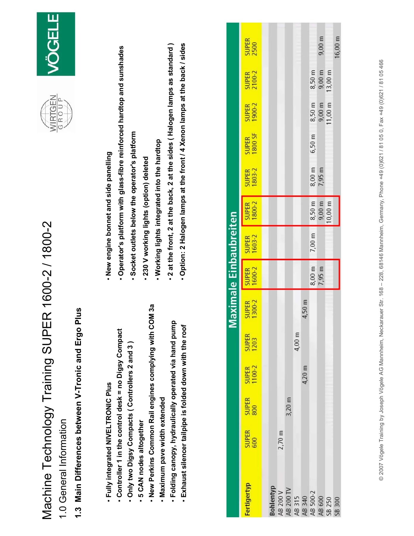
The opening chapter covers the main differences between the V-Tronic and Ego Plus control systems, including the control desk, lateral consoles, operator’s console, and screwless console layouts. It explains the pave widths and performance data for both machine models and identifies the key design distinctions that affect how the operator interfaces with the paver. This section is essential for anyone working on or operating either control variant, as it establishes which system is fitted and how the machine is configured.
Machine Operation — Operating Elements & Display
This chapter details the operating elements across the main operating console, left-hand module, centre module, right-hand module, and display module. Each control is identified with callout diagrams, including the potentiometer for pave speed control, reversing crawler tracks, emergency stop, auger and conveyor controls, and the joystick for traction. The display pages are documented screen by screen, covering tamper settings, vibrator settings, pressure bar settings, conveyor functions, extended auger functions, screed float off, screed assist, hydraulic auger height adjustment, and machine data readouts. Sensor calibration pages and parameter settings for the NivelTronic Plus system are also covered in detail.
Measured Values — Electrical & Hydraulic
The measured values chapter provides the electrical drive data, rpm sensor values, traction drive supply voltage, signal voltages, series resistances, and speed ranges for pedal mode, positioning mode, and travel mode. It includes conveyor sensor voltages, auger sensor voltages, and the measured electrical values for the tamper, vibrators, and screed assist systems. The hydraulic measurement values section covers the parking brake working pressure and the hydraulic brake specifications. These values are the baseline for diagnosing electrical and hydraulic faults on the machine.
Hydraulic System — Pumps, Motors, Valves & Filters
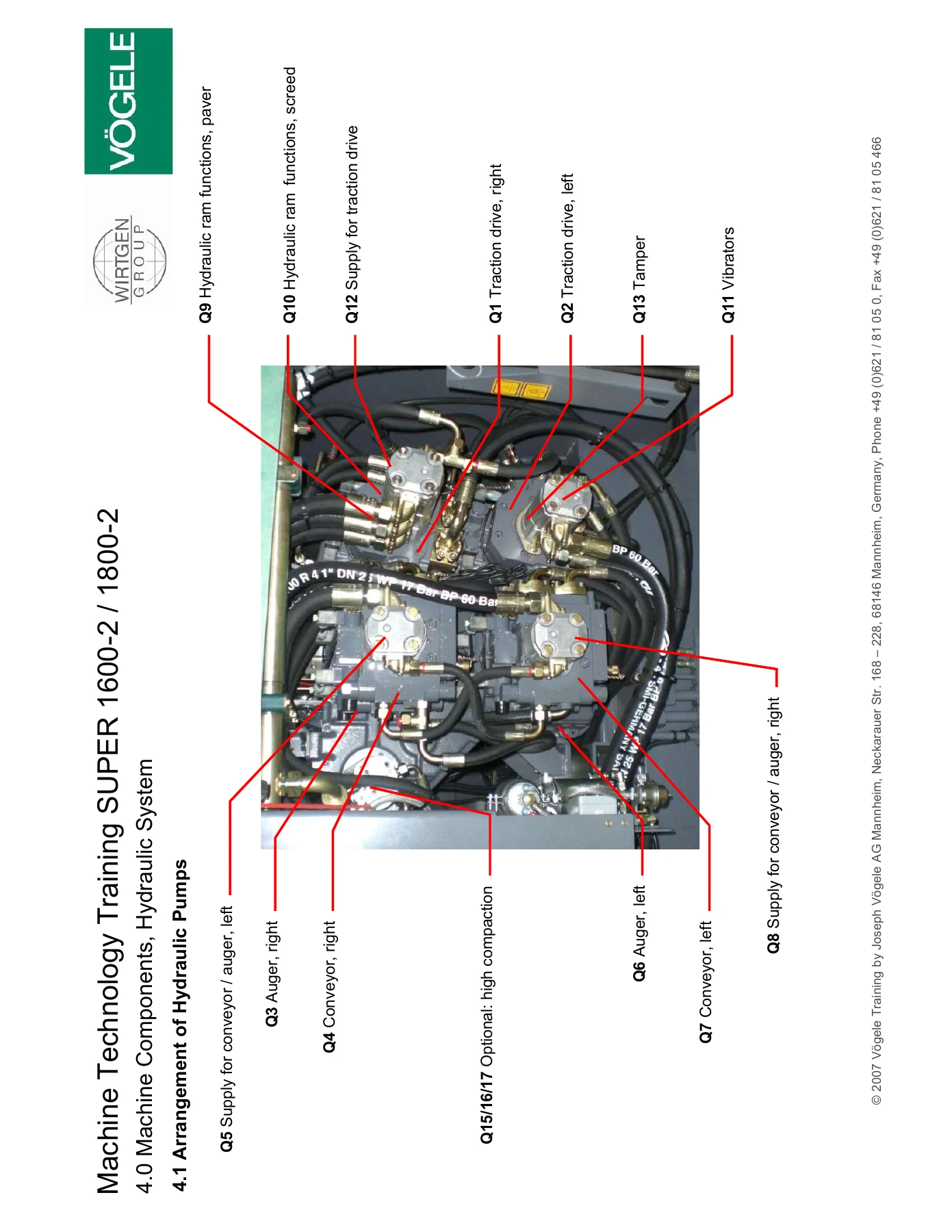
The hydraulic system chapter is heavily illustrated with exploded views and callout diagrams. It covers the arrangement of hydraulic pumps, the variable displacement axial piston pump HP 55-02-L for the traction drive, the variable displacement axial piston motor HMV 75-02 H1 for the traction drive, the hydraulic pump for conveyors, and the gerotor motor OMTS 200/250 for conveyors. Valve blocks ST1, ST2, ST4/ST5, ST6, and ST7 are documented with port identification, pressure limiting valves, directional valves, and proportional pressure reducing valves. The hydraulic filter, leakage oil filter F1, and central lubrication system are also covered, including the progressive grease distribution and delivery ports.
Electrical System — Terminal Box, CAN Bus & Generators
The electrical system chapter opens with the components in the terminal box, module B3, fuse assignment and rated amperage, and the B2 CAN bus module with terminating resistors. CAN nodes 1 through 5 are documented with node IDs, relay assignments, and sensor connections. The socket outlets on the terminal box and control box for screed heating are identified, along with the CAN node 5 control box for screed heating. The isolation monitoring system, voltage regulator, diagnostic function for screed heating, and three-phase AC generator options are all covered with wiring diagrams and terminal references.
Control Technology — CAN Bus Architecture
The control technology chapter maps the CAN 0 machine bus and CAN 1 screed bus, including the CAN high and CAN low wiring, terminating resistors, and the parallel connection of the two 120 ohm terminating resistors. Function assignments for the control desk and CAN nodes are detailed, showing how the control desk, Digsy Compact controllers, CAN nodes, and ECM Perkins engine communicate. The control desk node ID 1 with terminating resistor C1 R 1 120 ohm is documented, along with the machine bus wiring diagrams that show how the modules connect across the machine.
Perkins Diesel Engine — High-Pressure Fuel Lines & Sensors
The Perkins diesel engine chapter covers the high-pressure fuel lines for the 1104D engine, including the safety warnings about pressurized fuel and the procedures for checking and replacing high-pressure fuel lines. It documents the engine components with a view from the rear right, identifying the rear lifting lug, valve cover, front lifting lug, exhaust manifold, three-phase AC generator pulley, starter, flywheel, flywheel housing, turbocharger, and exhaust manifold. The sensor locations for the 1104D engine are shown from the front left, including coolant temperature sensor, intake-air temperature sensor, intake-air pressure sensor, fuel pressure sensor, electronic control module (ECM), oil pressure sensor, sensor for crankshaft position, and secondary position sensor.
Maintenance & Service Schedule
The maintenance and service schedule chapter provides a comprehensive table of maintenance work, material and spare parts, and service intervals at 8 hours, 50 hours, 500 hours, and 1000 hours. It covers the operator’s console, front wall, tamper strip, floor and steps, hopper walls, conveyor, distribution augers, push rollers, central lubricating system, engine oil level, engine coolant, generator V-belt, valve play, runbook suction filter, overflow oil filter, hydraulic tank release agent filter, all chain-track tensions, engine oil, engine oil filter, engine mounting, fuel tank, fuel filter, fuel pre-filter, air filter main filter, air filter safety cartridge, conveyor chain, distribution auger drive chains, conveyor drive chains, left/right conveyor gearbox oil, distribution auger gearbox oil, partial flow filter, hydraulic oil, pump distribution gearbox oil, feed pump oil filter, left/right traction drive gearbox oil, traction drive oil filter, crawler tracks, and hydraulic ram lugs.
Machine Data — Dimensions, Weights & Technical Specifications
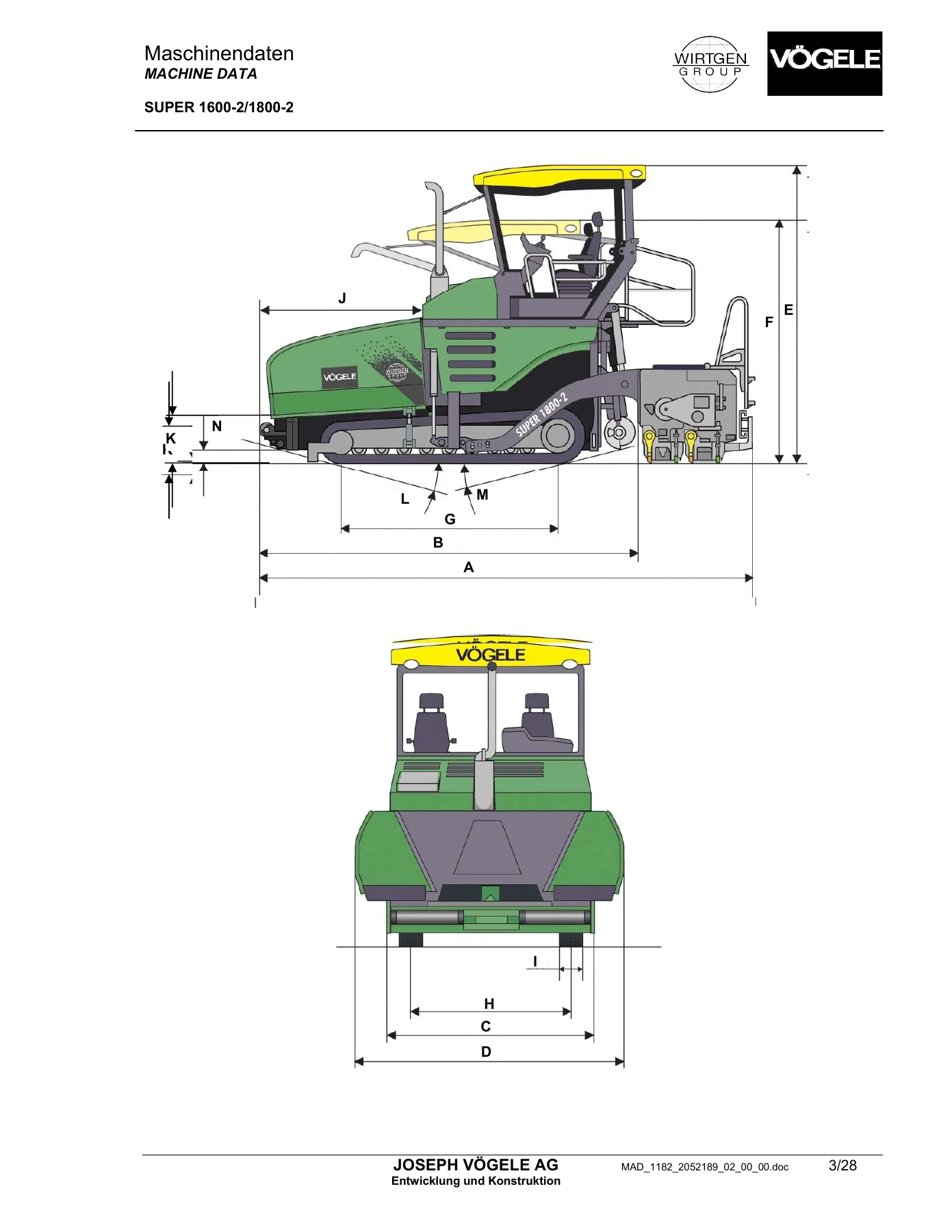
The machine data chapter contains the full technical specifications for both models. It includes the permissible total weight, dimensions with different screed configurations (SB 250, AB 500-2 TV, AB 500-2 TP1/TP2, AB 600 TV, AB 600 TP1/TP2), transport width, hopper open width, height with roof, height with canopy folded down, crawler-type vehicle length and axle base, track width, crawler-type vehicle width, hopper length, pouring height, ramp angles, ground clearance, engine data for the Perkins 1104D-E44TA and 1106D-E66TA, fuel and hydraulic tank capacities, electrical system data, traction drive speeds and pressures, material feed data for conveyors and augers, leveling system pressures, and screed data for tamper, vibrators, pressure bars, screed assist, and screed raise/lower times. The hydraulic function plan, electrical function plan, and bolt-on auger extensions with working widths from 4.0 to 10.0 m are also included.
Why This Vögele Paver Training Manual Matters
Working on a SUPER 1600-2 or SUPER 1800-2 without the correct machine technology reference is a recipe for guesswork. This manual gives you the actual hydraulic pressures, electrical voltages, CAN bus architecture, sensor locations, and measured values that Vögele specifies for these pavers. Whether you are troubleshooting a traction drive fault, calibrating the NivelTronic Plus sensors, diagnosing a CAN bus communication error, or setting up the screed heating system, the procedures and diagrams in this manual are the ones the machine was designed around. The exploded hydraulic views and electrical function plans let you trace circuits and hydraulic flows visually, which cuts diagnostic time dramatically compared to working blind.
IMAGES PREVIEW
Instant PDF Delivery — No Shipping, No Waiting
This Vögele SUPER 1600-2 and SUPER 1800-2 machine technology training manual is delivered as an instant PDF download immediately after purchase. There is no physical book to ship, no waiting for delivery, and no risk of a damaged or lost parcel. You can open the file on any device — laptop, tablet, or smartphone — and print the pages you need for the workshop. The diagrams, tables, and measured values are all there, ready to use on the job the moment you download. If you own, operate, or service these Vögele pavers, this manual is the reference you want within reach.

Reviews
There are no reviews yet.