
Volvo BL71 PLUS Backhoe Loader Electrical System Service Manual 2014
Original price was: $39.95.$24.95Current price is: $24.95.
Complete Volvo BL71 PLUS electrical system service information covering V-ECU and T-ECU control units, sensors, wiring diagrams 1-34, connector pinouts, troubleshooting procedures, battery, alternator, starter motor and preheating – 301-page 2014 PDF.
Description
Volvo BL71 PLUS Backhoe Loader Electrical System Service Manual
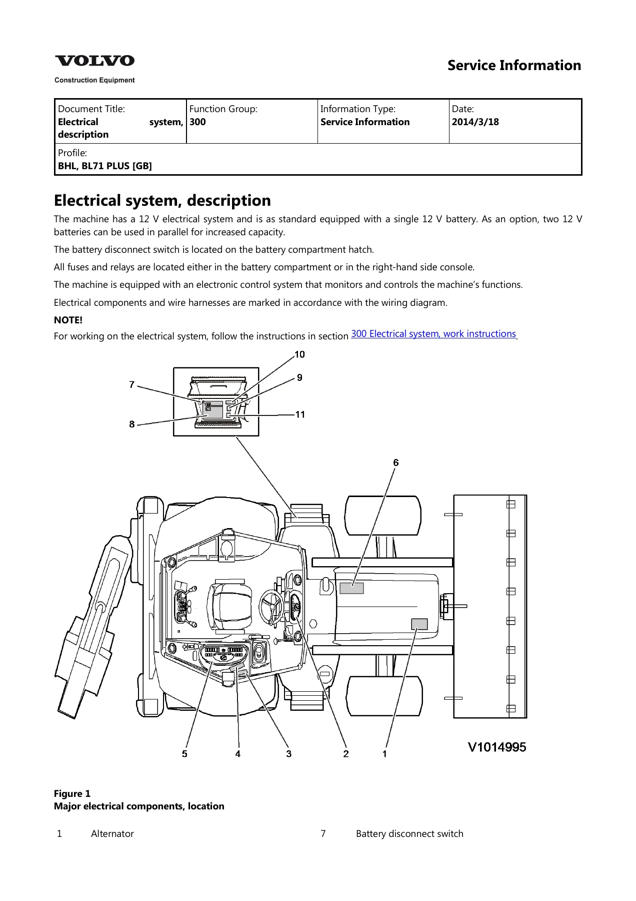
This Volvo Construction Equipment service information document covers the complete electrical system of the BL71 PLUS backhoe loader. It was issued on 2014/3/18 under function group 300 (Electrical system) and function group 370 (wiring, cables and component lists) for the BHL, BL71 PLUS [GB] profile. The material runs from a top-level system description down to individual pin assignments on the V-ECU and T-ECU connectors, and it finishes with the full set of wiring diagrams numbered 1 through 34.
Because it deals with the machine’s electronic backbone as well as the physical harness, this Volvo BL71 PLUS electrical system service manual is the reference to reach for whenever a fault, a warning light or a dead circuit needs to be traced properly rather than guessed at.
File Details
- Manual type: Electrical system service information
- Brand / manufacturer: Volvo Construction Equipment
- Model: BL71 PLUS backhoe loader (BHL)
- Function groups: 300 and 370
- Date of issue: 2014/3/18
- Language: English
- File format: PDF
- Pages: 301
Chapters Covered
- Electrical system, description
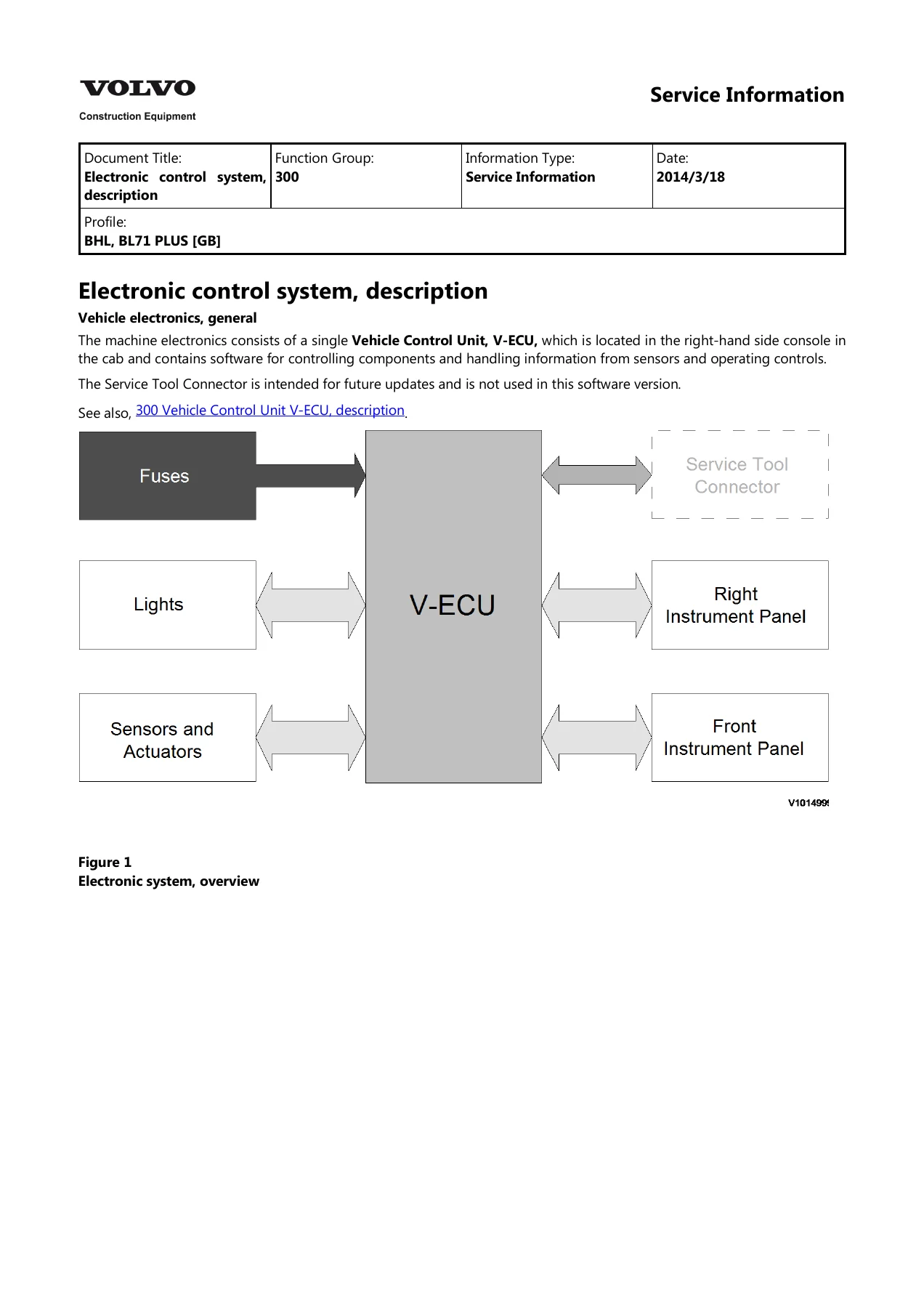
- Electronic control system, description
- Vehicle Control Unit V-ECU, description
- Limp-Home mode, by-passed V-ECU
- V-ECU, inputs and outputs
- V-ECU, software functions
- Transmission control unit T-ECU, description
- T-ECU, inputs and outputs
- TECU and Limp home mode
- Fuel shut-off
- Starter motor engagement
- Forward / Reverse / Neutral
- Hydraulic pump flow regulation
- Four-wheel drive
- Differential lock
- Direction indicators
- Hazard lights
- Working lights
- Hour meter
- Tachometer
- Service light and 500-hour reset procedure
- Loader lever lock
- Boom suspension system
- Code lock (option)
- Air conditioning compressor (option)
- Hydraulic attachment bracket, backhoe (option)
- Hydraulic attachment bracket, loader (option)
- Troubleshooting, general
- Collection of basic data
- Lead and connector checks
- Loader lever, electrical measuring
- Special tools and breakout harness pinouts
- Electrical troubleshooting, Powershift transmission
- Battery, description, charging and storage
- Alternator, description
- Starter motor, description
- Preheating, description
- Lighting, description
- Cables and wire number coding, description
- Component lists: antennas, distribution boxes and control units, diodes, fuses, heating coils, instruments, lights, LED indicators, motors, resistors, relays, sounders, sensors, switches, solenoid valves
- Wiring diagrams 1 through 34
As a whole, the document gives a technician a single continuous path from understanding how the BL71 PLUS is wired and controlled to actually repairing it. The control-system sections explain what each output is allowed to do and which input conditions have to be met before it activates – for example the conditions that must be satisfied before the starter motor is engaged, before the forward or reverse travel valves open, or before the hydraulic pump switches between excavator mode and loader mode. The component lists tie each fuse, relay, solenoid, sensor and lamp back to its wiring diagram row, and the wiring diagrams themselves close the loop by showing the physical routing.
Control units, inputs and outputs
Two electronic control units dominate the machine’s electrical architecture and both are documented in depth. The Vehicle Control Unit (V-ECU) sits inside the right-hand side console in the cab and carries the software that governs starter engagement, fuel shut-off, forward / reverse / neutral, reverse warning, four-wheel drive, differential lock, hydraulic pump flow regulation, boom suspension, loader lever lock, hour meter, service interval alert, direction and hazard lights, work lights, attachment brackets, hammer, air conditioning and the optional code lock.
The manual lists the V-ECU connector-by-connector pinout (X1 through X6) with wire numbers, signal types and the component each pin serves, then does the same for the Transmission Control Unit (T-ECU) on its X21, X22, X25 and X26 connectors for Power Shift machines. Because the T-ECU communicates with the V-ECU over a defined set of wires, having both pinout tables together in one document makes tracing an inter-unit fault far quicker than working from the wiring diagram alone.
A dedicated Limp-Home section shows how the V-ECU can be by-passed using the loose harness and connectors X17, X18 and X19 inside the right side console, which functions remain available when it is by-passed, and how to re-engage the unit afterwards.
Troubleshooting and measurement procedure
The troubleshooting material is written as a method rather than a fault list. It starts with a structured operator interview – machine and serial details, how and when the fault appears, whether it repeats and under what conditions, recent electrical work – so that the symptom is captured before anything is disturbed. From there it sets out the three classic checks used on this machine: open circuit tested by resistance between lead ends, short circuit to ground, and short circuit to voltage, each with the correct sequence of disconnecting the battery, removing the relevant connector and interpreting the reading.
Lead and connector inspection is covered in detail, including oxidation, terminal placement, mechanical contact, and cleaning pins and sleeves with compressed air and contact spray. A separate procedure walks through electrical measurement of the loader lever using a breakout harness and multimeter, with expected values for the 4-in-1 roller in neutral, forward and backward positions and the pin functions for forward, reverse, neutral, transmission disconnect and kick-down.
Component and system reference
Beyond the control logic, the manual documents the hardware side of the BL71 PLUS electrical system: battery location, charging and storage precautions, replacement sequence and ground cable routing; the 95 A alternator with integrated charge regulator and its belt drive; the starter motor and its solenoid; the manual electrical preheating circuit with its relay and glow plugs and the 30-second activation limit; and the standard lighting arrangement with four cab work lights and pre-wiring for additional lights on the cab superstructure and backhoe boom.
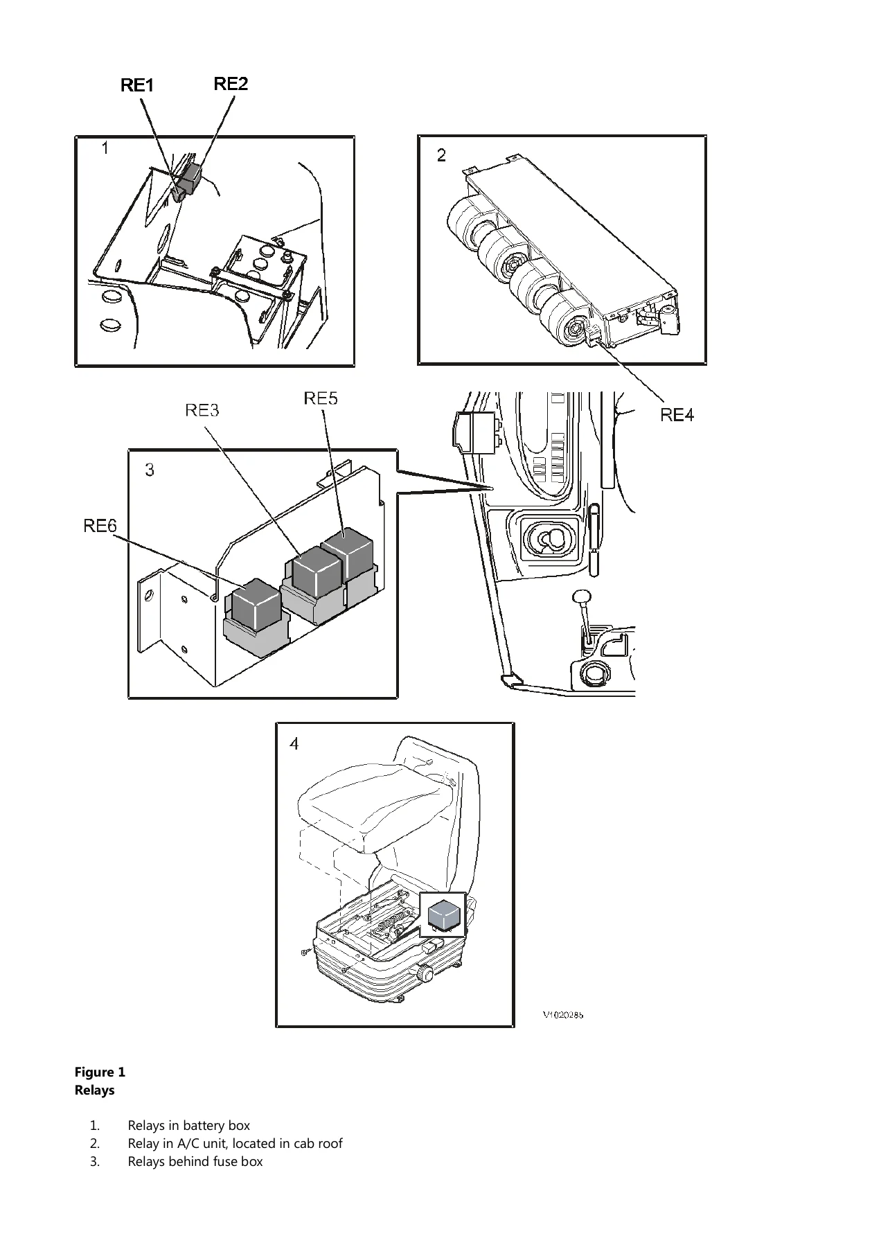
Wire harnesses are described as modular, one per principal function area, with colour coding following ISO 9247 and a three-digit wire number where the first digit identifies the circuit function. The component lists cover fuses with their ratings and locations in both the fuse box and battery compartment, relays in the battery box, cab roof, behind the fuse box, in the air suspended seat, behind the front dashboard and in the left joystick tower, plus sensors, switches, solenoid valves, LED indicators, motors, sounders and the Care Track antenna options.
What this manual lets you do
The Volvo BL71 PLUS Backhoe Loader Electrical System Service Manual supports real diagnosis and repair rather than parts swapping. With it a technician can read a fault back to a specific pin on the V-ECU or T-ECU, confirm which input conditions are missing before an output should activate, verify a circuit by resistance or voltage measurement, replace and re-seat connectors without causing secondary damage, and follow a wiring diagram row from a fuse through to the component it feeds.
That matters on a machine where the control unit manages so many functions at once. A starter that will not engage, a transmission that will not select forward, a 4WD that will not disengage, a working light circuit that keeps blowing fuses or a hydraulic pump stuck in the wrong power mode can all share deceptively similar symptoms. Working from the correct input conditions, wire numbers and connector pinouts is what separates a quick repair from a long one.
IMAGES PREVIEW
Delivered as an instant PDF download after payment, this Volvo BL71 PLUS electrical system service manual involves no shipping and no waiting. It opens on any computer, tablet or phone, can be printed for use in the workshop, and the wiring diagram and component list pages can be printed or displayed separately while you work at the machine.

Reviews
There are no reviews yet.