Description
File Details
- Manual type: Wiring diagram
- Brand / models: Volvo C30, S40 (04-), V50, C70 (06-)
- Document number: TP 39212202
- Coverage date: Wiring Diagram 2012; changes introduced up to and including structure week 11w20
- Language: English
- Page count: 341
- File format: PDF
What This Electrical Manual Covers
The Volvo C30 S40 V50 C70 2012 Wiring Diagram Manual TP39212202 is the electrical schematic book for the compact Volvo P1 family sold as the C30 hatch, S40 sedan from model year 2004 onward, V50 wagon, and C70 convertible from 2006 onward. Circuits are drawn in the key-removed, doors-closed state used throughout Volvo wiring publications. Left-hand drive and right-hand drive layouts appear wherever the harness path or module pin-out changes. Market notes on the front matter explain that illustrations may include equipment that is not fitted in every country.
Engine management pages split gasoline and diesel families rather than treating every car as identical. Diagrams name the B4164S3 1.6 l four-cylinder gasoline engine, B4204S3 and B4204S4 2.0 l four-cylinder gasoline engines, B5254T7 2.5 l five-cylinder turbo (T5), D4162T 1.6 l four-cylinder diesel, and D5204T 2.0 l five-cylinder diesel. Transmission pages cover automatic units AW55-51, AWF21 and MPS6 plus the manual M66. Start/stop, Flexifuel engine-heater wiring, Dual Xenon headlamps, keyless vehicle, BLIS, parking assistance, convertible-roof module on C70, and trailer modules are drawn as separate circuits instead of being buried in a single generic sheet.
Chapters Covered
- Vehicles with SRS / SIPS bag / IC — warnings and work rules
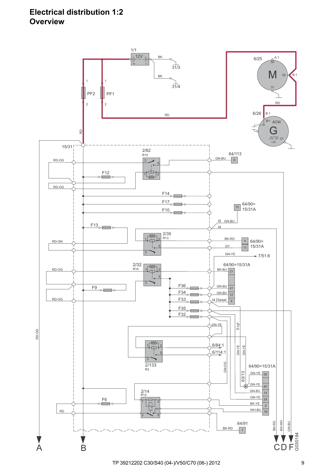
- Electrical distribution 1:2 — system overview
- Fuses — engine compartment distribution box F1–FH1, main fuse box battery 15/34, fuse holder midi 15/37, Central Electronic Module F43–F86, battery PF1–PF2
- Relays — ignition switch designations, engine-compartment R1–R14, extra holder, CEM R15–R18 and soldered R1–R11B, accessory relays
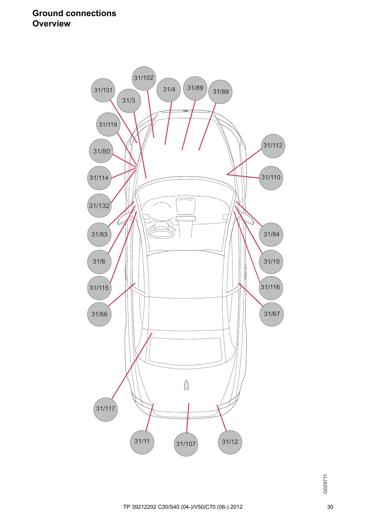
- Ground connections — overview and points 31/3 through 31/132 plus chassis grounds
- Control modules — locations, designations, CEM 1:2
- Data communication — low-speed CAN, high-speed CAN, MOST, LIN 1:2
- Ignition switch (SCU) and Accessory Electronic Module (AEM)
- Group 26 Cooling system — cooling fan
- Group 27 Engine controls — cruise control 4-cyl. / 5-cyl., start/stop function
- Group 28 Ignition / control system — EMS 4-cyl. 1.6 l, 4-cyl. 2.0 l, 5-cyl. turbo, diesel 1.6 l D4162T, diesel 5-cyl. 2.0 l; emission control 4-cyl. 1.6 l / 2.0 l and 5-cyl.
- Group 32 Alternator and voltage regulator — power supply 4-cyl. / 5-cyl.
- Group 33 Starting system — 4-cyl. / 5-cyl.
- Group 35 Lighting — high/low beam, Dual Xenon, running/parking/tail, brake, reverse, fog (including RHD Japan), interior, follow-me-home, instrument illumination, auxiliary lights
- Group 36 Additional electrical equipment — direction indicators and hazard, wipers/washers, rain sensor, parking assistance, keyless vehicle, immobilizer/SCL, horn, anti-theft alarm, alcohol lock, AEM
- Group 37 Wiring and fuses — 12 V outlets, diagnostics, towbar 4-/7-/13-pin harnesses, Accessory USB unit
- Group 38 Instruments — driver information module, seat-belt reminder
- Group 39 Other — audio, High Performance/Premium Sound, cellular phone, multimedia and traffic information, satellite radio, subwoofer C70, portable navigation, Bluetooth / handsfree variants with and without AEM
- Group 43 Transmission — AW55-51, AWF21, M66, MPS6
- Group 59 Brake system — brake control with STC and DSTC
- Group 64 Steering — speed-dependent power steering
- Group 83 Doors and openings — central locking, child safety lock, fuel filler flap, power windows, power sunroof / C70 power roof
- Group 84 Exterior decorative elements — power and heated door mirrors, heated rear window, BLIS
- Group 85 Interior equipment — power seats with and without memory (LHD/RHD), heated seats
- Group 87 Climate control — PTC elements, 4-cyl. gasoline, 1.6 l diesel, 5-cyl., parking/auxiliary heater, electric engine heater and Flexifuel heater
- Group 88 Internal equipment — auto-dimming rear-view mirror, supplemental restraint system C30/S40/V50 and C70, remote garage opener
- Connectors (from page 202)
- Branching points (from page 240)
- Cable harness routing in vehicle (from page 252)
- Component illustrations (from page 276)
- Index and list of components (from page 333)
Taken together, the Volvo C30 S40 V50 C70 2012 Wiring Diagram Manual TP39212202 gives a technician the power path from battery PF1/PF2 through distribution box 15/31 and CEM 4/56, the network map for every module that talks on CAN, LIN or MOST, and the body-side circuits that actually fail in service — lighting, locking, wipers, climate actuators, seats and SRS. Connector pin tables and harness-routing drawings then show where those wires live in the car, which is the difference between guessing at a splice and probing the correct cavity.
How the Diagrams Are Organized
Every component uses Volvo’s two-part designation: a type number plus a serial number. Type 1 is a battery, 2 a relay, 3 a switch, 4 a control module, 6 a motor, 7 a sensor, 10 a lamp, 11 a fuse, 31 a ground, 63 a branching point and 64 a connector. The list of components at the back converts 3/2 or 4/56 into a plain name such as light switch or Central Electronic Module. Junctions are numbered 63/xxx; each branching-point list names every device on that splice. Connectors 64/xxx document the bridge between two harnesses, including cavity numbers and which harness sits on each side of the plug.
Wire colors follow the book’s own codes: BK/SB black, BN brown, BU/BL blue, GN green, GY/GR gray, OG/OR orange, RD/R red, WH/W white, YE/Y yellow and the remaining mixed colors printed on each conductor. Ignition feeds are marked X (audio/accessory), S (powered when the key is inserted), 15 (remains live during crank), 15l (opens while starting), 30 (battery constant) and 50 (start). Symbols distinguish system voltage, chassis ground, screened cable, twisted pair, CAN-H / CAN-L, LIN, MOST and inter-harness connectors. Variants that exist only on one body style or engine are drawn with a dashed variant line rather than mixed into the base circuit.
Fuses, Relays and Ground Points
Engine-compartment box 15/31 lists F1 through FH1 with ampere ratings and the downstream device. Examples printed in the tables include F1 cooling-fan control module at 50 A, F2 electrical power steering module at 80 A, F5 PTC element at 80 A, F7/F8 brake control module pump and valves at 30 A / 20 A, F9 engine-management main relay at 30 A, F13 starter motor at 30 A and F17 wiper motor module at 30 A. CEM fuses F43–F86 feed infotainment, SRS, 12 V outlets, lighting switch and DIM, washer/wiper relays, keyless vehicle module, door modules, power seats and cargo lighting. Battery mega-fuses PF1 and PF2 are both 150 A; the main fuse box at the battery adds 11M/1 at 125 A for the alternator / engine-compartment feed and 11M/2 at 15 A for the battery monitoring sensor.
Relay maps name R14 as the engine-management main relay 2/32, R13 as starter relay 2/35, R10 as heated-rear-window relay 2/82, R2 as horn relay 2/17 and the CEM-soldered set that includes interior lighting 2/89, reversing lights 2/80, washer motors 2/92 and 2/93, high beam 2/63 and infotainment 2/159. Ground overview drawings place 31/3 and 31/132 at the left MacPherson strut tower, 31/4 on the engine, 31/10 / 31/116 at the A-posts, 31/66 / 31/67 at the seat risers and 31/11 / 31/12 at the rear corners, then list every module tied to each stud.
Complete PDF Bookmark Tree
Complete Bookmarks
The complete bookmarks in the “Volvo C30 S40 V50 C70 2012 Wiring Diagram Manual TP39212202” are as follows:
VOLVO C30, S40 (04-), V50 & C70 (06-)p. 1
TP 39212202p. 1
Vehicles with SRS (Airbag)/SIPS bag/IC (Inflatable curtain)p. 2
+Table of Contents 1:3p. 3
Table of Contents 2:3p. 4
Table of Contents 3:3p. 5
+Explanationsp. 6
Abbreviationsp. 6
How to use the wiring diagrams 1:2p. 7
+Electrical distribution 1:2p. 9
Electrical distribution 2:2p. 10
+Fusesp. 11
Engine compartment distribution box F1-F10p. 11
Distribution box in engine compartment F11-F20p. 12
Distribution box in engine compartment F21-F31p. 13
Distribution box in engine compartment F32-F34p. 14
Distribution box in engine compartment F35-FH1p. 15
Main fuse box batteryp. 16
Fuse holder midip. 17
Central Electronic Module (CEM) F43-F48p. 18
Central Electronic Module (CEM) F49-F61p. 19
Central Electronic Module (CEM) F62-F69p. 20
Central Electronic Module (CEM) F73-F85p. 21
Central Electronic Module (CEM) F86p. 22
Battery PF1-PF2p. 23
+Relaysp. 24
Ignition switch and relaysp. 24
Distribution box in engine compartment R1-R14p. 25
Engine compartmentp. 26
Central electronic module (CEM) R15-R18p. 27
Central electronic module (CEM) R1-R11Bp. 28
Other relaysp. 29
+Ground connectionsp. 30
Overviewp. 30
31/3 – 31/10 contp. 31
31/10 – 31/12p. 32
31/66 – 31/67p. 33
31/80 – 31/107p. 34
31/110 – 31/115p. 35
31/116 – 31/132p. 36
Grounded to chassisp. 37
+Control modulesp. 38
Overview locationsp. 38
Overview designationsp. 39
+Central electronic module (CEM) 1:2p. 40
Central electronic module (CEM) 2:2p. 41
+Data communication, Low speed CAN 1:2p. 42
Data communication, Low speed CAN 2:2p. 43
Data communication high speed CANp. 44
Data communication MOSTp. 45
+Data communication, LIN 1:2p. 46
Data communication, LIN 2:2p. 47
Ignition switch (SCU)p. 48
Accessory electronic module (AEM)p. 49
+Group 26 Cooling systemp. 50
+Group 27 Engine controlsp. 51
Cruise control 4-Cyl.p. 51
Cruise control 5-Cyl.p. 52
Start/stop functionp. 53
+Group 28 Ignition system/control systemp. 54
+Engine management system, 4-Cyl. 1.6l 1:2p. 54
Engine management system, 4-Cyl. 1.6l 2:2p. 55
+Engine management system, 4-Cyl. 2.0l 1:2p. 56
Engine management system, 4-Cyl. 2.0l 2:2p. 57
+Engine management system, 5-Cyl. Turbo 1:2p. 58
Engine management system, 5-Cyl. Turbo 2:2p. 59
+Engine management system Diesel, 4-Cyl. 1.6l D4162T 1:2p. 60
Engine management system Diesel, 4-Cyl. 1.6l D4162T 2:2p. 61
+Engine management system Diesel, 5-Cyl. 2.0l 1:3p. 62
Engine management system Diesel, 5-Cyl. 2.0l 2:3p. 63
Engine management system Diesel, 5-Cyl. 2.0l 3:3p. 64
Emission control 4-Cyl. 1.6lp. 65
Emission control 4-Cyl. 2.0lp. 66
Emission control 5-Cyl.p. 67
+Group 32 Alternator and voltage regulatorp. 68
Power supply 4-Cyl.p. 68
Power supply 5-Cyl.p. 69
+Group 33 Starting systemp. 70
Starting system 4-Cyl.p. 70
Starting system 5-Cyl.p. 71
+Group 35 Lightingp. 72
High and low beamp. 72
Active headlight, (Dual Xenon)p. 73
Running light/Parking light, Tail lights S40/V50p. 74
Running light/Parking light, Tail lights (Dual Xenon) S40/V50p. 75
Running light/Parking light, Tail lights C30/C70p. 76
Running light/Parking light, Tail lights (Dual Xenon) C30/C70p. 77
Brake lights S40/V50p. 78
Brake lights C30/C70p. 79
Reversing lights S40/V50p. 80
Reversing lights C30/C70p. 81
Fog lights S40/V50p. 82
Fog lights C30/C70p. 83
Fog lights RHD Japan S40/V50p. 84
Fog lights RHD Japan C30/C70p. 85
+Interior lighting C30/S40/V50 1:2p. 86
Interior lighting C30/S40/V50 2:2p. 87
+Interior lighting C70 1:2p. 88
Interior lighting C70 2:2p. 89
Follow-me-home lightingp. 90
Instrument and control illuminationp. 91
Auxiliary lightsp. 92
+Group 36 Additional electrical equipmentp. 93
Direction indicator and Hazard warning flashers S40/V50p. 93
Direction indicator and Hazard warning flashers (Dual Xenon) S40/V50p. 94
Direction indicator and Hazard warning flashers C30/C70p. 95
Direction indicator and Hazard warning flashers (Dual Xenon) C30/C70p. 96
Wiper/washer windshieldp. 97
Washer headlightsp. 98
Wiper/washer rear window C30/V50p. 99
Rain sensorp. 100
Parking assistancep. 101
+Keyless vehicle C30/S40/V50 1:2p. 102
Keyless vehicle C30/S40/V50 2:2p. 103
+Keyless vehicle C70 1:2p. 104
Keyless vehicle C70 2:2p. 105
Immobilizer/Steering column lock (SCL)p. 106
Hornp. 107
Anti-theft alarm C30p. 108
Anti-theft alarm S40/V50p. 109
Anti-theft alarm C70p. 110
Alcohol lockp. 111
Accessory Electronic Module (AEM) C30p. 112
Accessory Electronic Module (AEM), S40/V50/C70p. 113
+Group 37 Wiring and fusesp. 114
12V outlet C30/S40/V50p. 114
12V outlet, C70p. 115
Diagnostics systemp. 116
Cable harness towbar/tow hitch 4-pin S40/V50p. 117
Cable harness towbar/tow hitch 4-pin C30p. 118
Cable harness towbar/tow hitch 7-pin S40/V50p. 119
Cable harness towbar/tow hitch 7-pin C30/C70p. 120
Cable harness towbar/tow hitch 13-pin S40/V50/C70p. 121
Cable harness towbar/tow hitch 13-pin C30p. 122
Accessory USB unit (AUU)p. 123
+Group 38 Instrumentsp. 124
Driver information modulep. 124
Seat belt reminder C30/S40/V50p. 125
Seat belt reminder C70p. 126
+Group 39 Otherp. 127
Audio C30/S40/V50p. 127
Alternative connection audio S40/V50p. 128
Audio C70p. 129
+Audio High Performance/Premium Sound C30/S40/V50 1:2p. 130
Audio High Performance/Premium Sound C30/S40/V50 2:2p. 131
+Audio High Performance/Premium Sound C70 1:2p. 132
Audio High Performance/Premium Sound C70 2:2p. 133
+Cellular phone 1:2p. 134
Multimedia & Traffic informationp. 136
Satellite radiop. 137
Subwoofer C70p. 138
Navigation system, portablep. 139
Bluetoothp. 140
Bluetooth Handsfree, internal amplifierp. 141
Bluetooth Handsfree, external amplifierp. 142
Bluetooth Handsfree & AUU, internal amplifierp. 143
Bluetooth Handsfree & AUU, external amplifierp. 144
Bluetooth Handsfree with AEM, internal amplifier, LHDp. 145
Bluetooth Handsfree with AEM, internal amplifier, RHDp. 146
Bluetooth Handsfree with AEM, external amplifier, LHDp. 147
Bluetooth Handsfree with AEM, external amplifier, RHDp. 148
+Group 43 Transmissionp. 149
Automatic transmission AW55-51p. 149
Automatic transmission AWF21p. 150
Transmission M66p. 151
Automatic transmission MPS6p. 152
+Group 59 Brake systemp. 153
Brake control system & STCp. 153
Brake control system & DSTCp. 154
+Group 64 Steeringp. 155
Speed dependent power steeringp. 155
+Group 83 Doors and openingsp. 156
Central locking front doors C30/S40/V50p. 156
Central locking rear doors S40/V50p. 157
Central locking C70p. 158
Central locking trunk lid/tailgate C30p. 159
Central locking trunk lid/tailgate S40/V50p. 160
Central locking trunk lid/tailgate C70p. 161
Central locking storage compartment C70p. 162
Child safety lock S40/V50p. 163
Central locking fuel filler flapp. 164
Signal receiver central locking C30/S40/V50p. 165
Signal receiver central locking C70p. 166
Power windows front doors C30/S40/V50p. 167
Power windows C70p. 168
Power windows rear doors S40/V50p. 169
Power sunroof C30/S40/V50p. 170
Power roof C70p. 171
+Group 84 Exterior decorative elements, etc.p. 172
Power door mirrors C30/S40/V50p. 172
Power door mirrors C70p. 173
Heated door mirrorsp. 174
Heated rear windowp. 175
Blind spot information systemp. 176
+Group 85 Interior equipmentp. 177
Power driver’s seat with memory function LHD S40/V50p. 177
Power driver’s seat with memory function RHD S40/V50p. 178
Power driver’s seat with memory function LHD C30/C70p. 179
Power driver’s seat with memory function, RHD C30/C70p. 180
Power driver’s seat LHDp. 181
Power driver’s seat RHDp. 182
Power passenger seat LHD S40/V50p. 183
Power passenger seat RHD S40/V50p. 184
Heated seatsp. 185
+Group 87 Climate control systemp. 186
Climate control system PTC-elementsp. 186
+Climate control system, 4-Cyl. Gasoline 1:2p. 187
Climate control system, 4-Cyl. Gasoline 2:2p. 188
+Climate control system, Diesel 1.6l 1:2p. 189
Climate control system, Diesel 1.6l 2:2p. 190
+Climate control system, 5-Cyl. 1:2p. 191
Climate control system, 5-Cyl. 2:2p. 192
Parking heater, auxiliary heaterp. 193
Relay, electric engine heaterp. 194
Electric engine heater Flexifuelp. 195
+Group 88 Internal equipmentp. 196
Rear-view mirror with automatic dimmingp. 196
+Supplemental restraint system C30/S40/V50 1:2p. 197
Supplemental restraint system C30/S40/V50 2:2p. 198
+Supplemental restraint system C70 1:2p. 199
Supplemental restraint system C70 2:2p. 200
Remote control garage openingp. 201
+Connectorsp. 202
64/10B – 64/27p. 202
64/30:1-13p. 203
64/30:14-20p. 204
64/31:1-13p. 205
64/31:14-20p. 206
64/35p. 207
64/41 RHDp. 208
64/41:1-24 LHDp. 209
64/41:25-26 LHD – 64/43:1-13 LHDp. 210
64/43:14-26 LHD – 64/43:1-4 RHDp. 211
64/43:5-24 RHDp. 212
64/43:25-26 – 64/45p. 213
64/47 – 64/48:1-4p. 214
64/48:5-8 C30/S40 – 64/48 V50p. 215
64/48A C30 – 64/50p. 216
64/51p. 217
64/53 – 64/80 C70p. 218
64/80A – 64/90:1-4p. 219
64/90:5-10p. 220
64/90:11-15p. 221
64/90:16-21p. 222
64/90:22-28p. 223
64/90:29-34p. 224
64/90:35-41p. 225
64/91 – 64/111:1-17p. 226
64/111:18-27 – 64/112p. 227
64/113:1-20p. 228
64/113:21-29 – 64/191p. 229
64/231 C70 – 64/232 C70p. 230
64/233 C70 – 64/245 C70p. 231
64/246 C70 – 64/322p. 232
64/333 C30 – 64/425p. 233
64/545p. 234
64/596 C70 – 64/661 C70p. 235
64/662 C70 – 64/707 C70p. 236
64/707 C70 – 64/791 C30p. 237
64/816 – 64/956 C30p. 238
64/1300 – 64/1400p. 239
+Branching pointsp. 240
63/5 – 63/25p. 240
63/26 – 63/52p. 241
63/53 – 63/63p. 242
63/67 – 63/93p. 243
63/95 – 63/126p. 244
63/130 – 63/174p. 245
63/175 – 63/211p. 246
63/212 – 63/221p. 247
63/222 – 63/255p. 248
63/256 – 63/328p. 249
63/339 – 63/616p. 250
63/1000 – 63/US02p. 251
+Cable harness routing in vehiclep. 252
Engine harness, gasoline 4-Cyl.1.6lp. 252
Engine harness, gasoline 4-Cyl.2.0lp. 252
Engine harness, gasoline 5-Cyl. Turbop. 253
Engine harness, Diesel 1.6lp. 253
Harness engine, Diesel 2.0lp. 254
Engine compartment harness, 4-Cyl.p. 255
Engine compartment harness, 5-Cyl.p. 255
Harness dashboard, LHDp. 256
Harness Dashboard, RHDp. 256
Floor harness, C30 LHDp. 257
Floor harness, C30 RHDp. 258
Floor harness, S40 LHDp. 259
Floor harness, S40 RHDp. 260
Floor harness, V50 LHDp. 261
Floor harness, V50 RHDp. 262
Floor harness, C70 LHDp. 263
Floor harness, C70 RHDp. 264
Roof harness, C30p. 265
Roof harness, S40p. 265
Roof harness, V50p. 266
Roof harness, C70p. 266
Tunnel harness, C30/S40/V50p. 267
Tunnel harness, C70p. 267
Driver’s door harness, C30p. 268
Passenger door harness, C30p. 268
Driver’s door harness, S40/V50p. 269
Passenger door harness, S40/V50p. 269
Driver’s door harness, C70p. 270
Driver’s door harness supplement, C70p. 270
Passenger door harness, C70p. 271
Passenger door harness supplement, C70p. 271
Harness rear door, right S40/V50p. 272
Harness rear door, left S40/V50p. 272
Rear side panel harness, left C70p. 273
Rear side panel harness, right C70p. 273
Trunk lid/tailgate harness, C30p. 274
Trunk lid/tailgate harness, S40p. 274
Trunk lid/tailgate harness, V50p. 275
Trunk lid/tailgate harness, C70p. 275
+Component illustrationsp. 276
1/1 – 2/35p. 276
2/63 – 2/142p. 277
2/159 – 3/1p. 278
3/4 – 3/35p. 279
3/35 – 3/78p. 280
3/78 – 3/100p. 281
3/110 – 3/157p. 282
3/173 – 3/271p. 283
3/273 – 3/288p. 284
3/288 – 4/46.2p. 285
4/46.3 – 4/71p. 286
4/76 – 4/114p. 287
4/119 – 6/17p. 288
6/18 – 6/35p. 289
6/37 – 6/67p. 290
6/71 – 6/118p. 291
6/120 – 7/12p. 292
7/15 – 7/31p. 293
7/32 – 7/71p. 294
7/74 – 7/110p. 295
7/111 – 7/134p. 296
7/143 – 7/164p. 297
7/165 – 7/182p. 298
7/190 – 7/220p. 299
7/221 – 7/240p. 300
7/243 – 8/32p. 301
8/33 – 8/48p. 302
8/51 – 8/67p. 303
8/67 – 8/98p. 304
8/99 – 8/128p. 305
8/129 – 9/12p. 306
9/13 – 9/34p. 307
9/38 – 10/12p. 308
10/13 – 10/18p. 309
10/19 – 10/27p. 310
10/29 – 10/45p. 311
10/46 – 10/50p. 312
10/50 – 10/53p. 313
10/53 – 10/66p. 314
10/68 – 10/150p. 315
10/150 – 16/3p. 316
16/4 – 16/35p. 317
16/45 – 16/98p. 318
16/105 – 16/138p. 319
16/140 – 16/155p. 320
16/156 – 17/40p. 321
17/42 – 31/10p. 322
31/11 – 31/102p. 323
31/107 – 64/10Bp. 324
64/25G – 64/48Ap. 325
64/48 – 64/80Ap. 326
64/90 – 64/179p. 327
64/190 – 64/250p. 328
64/322 – 64/663p. 329
64/707 – 64/978p. 330
64/1300 – R/no.p. 331
4X/110 – 64X/322p. 332
+Index 1:2p. 333
+List of components 1:7p. 335
List of components 2:7p. 336
List of components 3:7p. 337
List of components 4:7p. 338
List of components 5:7p. 339
List of components 6:7p. 340
List of components 7:7p. 341
Networks, Engines and Body Systems
High-speed CAN pages show the ECM, BCM, TCM and CEM exchanging the engine, brake and transmission traffic. Low-speed CAN and LIN cover comfort modules — door modules DDM/PDM/LDM/RDM, climate control module, steering wheel module, rain sensor, seat heaters and the keyless vehicle module. MOST appears on the audio and multimedia path. Engine sheets then drop to injector, coil or glow-plug level: four-cylinder gasoline EMS on pages 54–57, five-cylinder turbo on 58–59, D4162T diesel on 60–61 and 2.0 l five-cylinder diesel on 62–64, followed by the matching emission-control oxygen-sensor and EVAP / EGR drawings.
Lighting is split by body and by Dual Xenon versus halogen so a C30 tail-lamp circuit is not used on an S40. The same split is used for direction indicators, fog lamps (including a Japan RHD variant), interior lamps and follow-me-home. Body groups continue through central locking and power windows per door count, C70 convertible roof module 4/59, power and heated mirrors, BLIS cameras, memory and non-memory power seats, heated seats, ECC damper motors, parking heater / CPM, SRS igniters and inflatable curtains, and the full audio / Bluetooth / phone tree with internal versus external amplifier and LHD versus RHD AEM layouts.
Connectors, Harness Maps and Component Pictures
From page 202 the book becomes a connector catalogue — 41-pin engine connector 64/90, 29-pin floor-to-engine 64/113, 27-pin dash 64/111, 26-pin door plugs 64/41 and 64/43, plus the C70-only roof and side-panel housings. Branching-point lists from page 240 tell you which components share a splice such as 63/53 on four-cylinder engines. Harness-routing plates from page 252 overlay those numbers on engine, dash, floor, roof, tunnel, door, rear-side and tailgate looms for C30, S40, V50 and C70 in both LHD and RHD. Component illustrations from page 276 then show the physical part that belongs to each designation, from battery 1/1 through CEM 4/56, door modules, lamps and the ground studs.
Use This Manual on the Car
With the Volvo C30 S40 V50 C70 2012 Wiring Diagram Manual TP39212202 open you can trace a dead circuit from fuse rating to relay coil to module pin, confirm whether a lamp is CEM-controlled or hard-wired, locate the correct ground before replacing a harness, and identify the right engine-management sheet for a D4162T versus a B5254T7. Correct fuse values, wire colors and connector cavities stop the usual shop mistakes — pulling F18 when the fault is on F4, probing the wrong 64/90 cavity, or treating a C70 roof circuit as an S40 tailgate circuit. After payment the file is delivered as an instant PDF. There is no boxed shipment to wait for. Open it on a laptop, tablet or phone in the bay and print the sheet you need for the fender or the bench.

Reviews
There are no reviews yet.