
Volvo XC70 (08-) & S80 (07-) 2012 Wiring Diagram Manual TP39217202
Original price was: $31.95.$17.95Current price is: $17.95.
2012 Volvo wiring diagram publication TP 39217202 for XC70 (08-) and S80 (07-) electrical systems, covering fuse boxes, grounds, CAN/LIN/MOST networks, engine-variant circuits, and harness routing through structure week 11w20.
Description
Volvo XC70 (08-) & S80 (07-) 2012 Wiring Diagram Manual TP39217202
This PDF is the 2012 electrical wiring diagram book printed as TP 39217202 for Volvo XC70 models from model year 2008 onward and Volvo S80 models from model year 2007 onward. Circuit sheets are drawn in the non-active state with the key removed and doors, hatches, and hood closed. Content reflects changes introduced up to and including structure week 11w20; later vehicle changes are outside this edition. Many sheets also split V70 wagon and S80 sedan body circuits, and separate left-hand drive from right-hand drive where the harness path differs.
File Details
- Manual type: Wiring diagram
- Brand / models: Volvo XC70 (08-), Volvo S80 (07-); V70 body circuits appear throughout the lighting, locking, and harness sections
- Language: English
- Page count: 364
- File format: PDF
- Document number: TP 39217202
- Edition year: 2012
- Coverage cutoff: structure week 11w20
How the Sheets Are Organized
Every component uses a two-part designation: a type number plus a serial number. Type 1 is the battery, 2 relays, 3 switches, 4 control modules, 6 motors, 7 sensors, 8 actuators, 9 heating elements, 10 lamps, 11 fuses, 15 distribution boxes, 31 ground points, 73 branching points, and 74 connectors. The Volvo XC70 (08-) & S80 (07-) 2012 Wiring Diagram Manual TP39217202 explains those codes, wire-color abbreviations (BK/SB black, RD/R red, BU/BL blue, GN green, YE/Y yellow, and the remaining palette), ignition-switch feeds (X, S, 15, 15I, 30, 50), and the graphic symbols for system voltage, chassis ground, screened or twisted pairs, CAN-H/CAN-L, LIN, MOST, and harness-to-harness connectors.
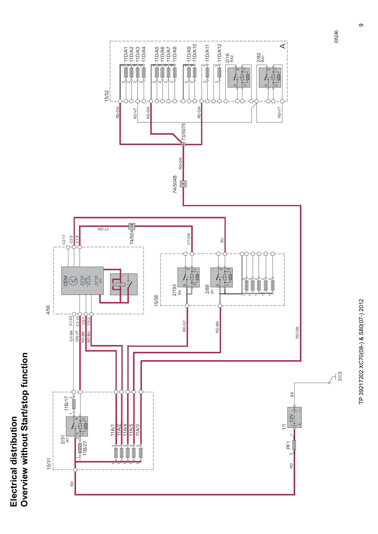
Power distribution is drawn twice: one overview without Start/Stop and a second overview with Start/Stop, extra battery feed PF4, and the cold-zone box 15/37. From those overviews the book drops into distribution box 15/31 in the engine compartment, 15/36 in the passenger compartment, 15/32 in the cargo area, CEM internal fuses, battery main fuses PF1–PF2, and the cold-zone fuse layout. Relay maps sit next to those boxes, including CEM-soldered relays K1 and following.
Chapters Covered
- Vehicles with SRS / SIPS bag / IC — working precautions
- Explanations — group numbers, ignition symbols, markets, colors
- How to use the wiring diagrams — component codes, branching points, connectors, data buses
- Electrical distribution — overviews with and without Start/Stop; engine, passenger, and cargo boxes
- Fuses — engine-compartment F1–F44; CEM F1–F24; passenger extra holder; passenger box F1–F30; cargo FA1–FA11; cold zone; battery PF1–PF2
- Relays — engine compartment, passenger compartment, cargo compartment, CEM
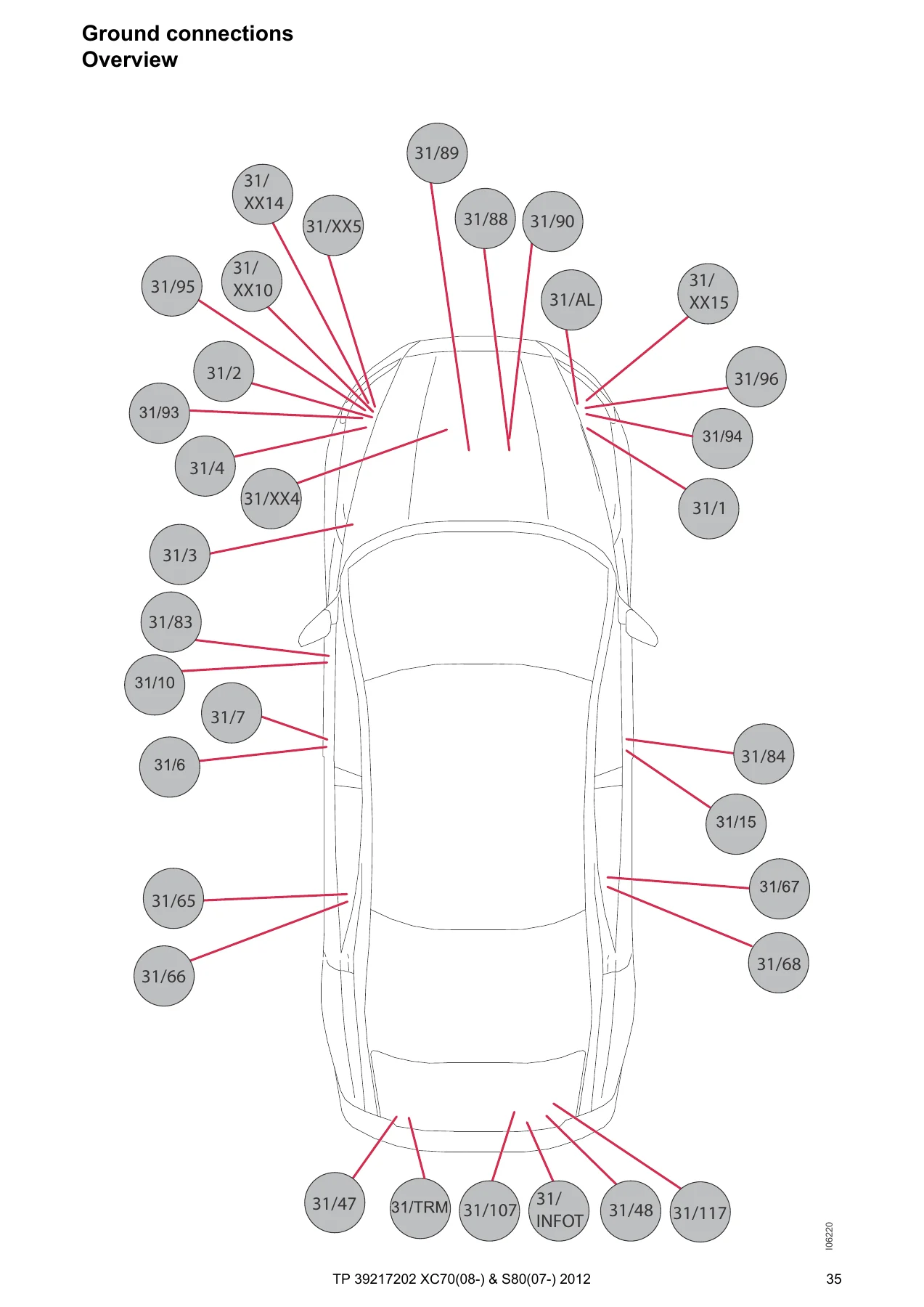
- Ground connections — overview plus points 31/1 through 31/AL, 31/INFOT, 31/TRM
- Control modules — locations, designations, CEM 1:3, high-speed CAN, 4-cyl. high-speed CAN, intermediate-speed CAN LHD/RHD, LIN, MOST, Steering Wheel Module
- Group 26 Cooling system — cooling-fan circuits for 4-cyl. turbo, 5-cyl. turbo and 6-cyl., 4-cyl. diesel, 5-cyl. diesel
- Group 27 Engine controls — cruise control by engine family; Start/Stop for 4-cyl. 1.6l turbo, 4-cyl. 1.6l diesel DV6C, 5-cyl. 1.6l diesel VED5
- Group 28 Ignition and control — engine management B4164T; B4204T6/T7; B5254T10; D4162T; D5244T11/T15/T17 and D5204T3; B6324S4; B6324S5; B6304T4; emission control 4-/5-/6-cyl.
- Group 32 Alternator and voltage regulator — power supply 4-cyl. turbo, 4-cyl. with Start/Stop, 5-cyl. and 6-cyl.
- Group 33 Starting system — 4-cyl. turbo, 5- and 6-cyl., 4-cyl. diesel, 5-cyl. diesel
- Group 35 Lighting — high/low beam, Dual Xenon, manual beam-length adjustment, running/parking/tail lamps V70 and S80, fog, brake, reversing, follow-me-home LHD/RHD, interior lighting LHD/RHD, active headlight, sill, auxiliary, mug-holder and floor lamps
- Group 36 Additional electrical equipment — rain sensor, direction indicators and hazard LHD/RHD for V70 and S80, wipers and washers, headlight washer, keyless vehicle, horn, anti-theft alarm, parking assistance, collision warning with brake booster, TPMS, alcohol lock
- Group 37 Wiring and fuses — diagnostics, 12 V outlets, towbar harnesses 4-/7-/13-pin for V70 and S80, Accessory USB unit
- Group 38 Instruments — seat-belt reminder, Driver Information Module, analog clock
- Group 39 Other — cellular phone, audio and audio premium, DAB, Bluetooth telephone and handsfree, rear-seat entertainment, satellite radio, parking camera, portable navigation, TV
- Group 43 Transmission — M66 and MMT 6, TF-80SC AWD, MPS6, AWF21, Differential Electronic Module
- Group 55 Parking brake — electric parking brake
- Group 59 Brake system — brake control and DSTC
- Group 64 Steering — speed-dependent power steering
- Group 76 Shock absorbers — Four-C
- Group 83 Doors and openings — central locking LHD/RHD front, rear, trunk/tailgate V70 and S80, fuel flap, signal receiver; power windows; power sunroof
- Group 84 Exterior decorative elements — power and heated mirrors LHD/RHD, BLIS LHD/RHD, heated rear window
- Group 85 Interior equipment — memory driver seat LHD/RHD, passenger seat LHD/RHD, heated seats with and without fans, heated rear seat, massage seats
- Group 87 Climate control — PTC elements; 4-cyl. turbo; 4-cyl. diesel; 5- and 6-cyl.; parking/auxiliary heater and remote start; rear refrigeration box
- Group 88 Internal equipment — auto-dimming mirror, supplemental restraint system, power folding headrest, garage-door remote
- Group 89 Body other — radiator masking blind
- Connectors — pin-out tables from 74/9 through 74/1503
- Branching points — 73/3004 through 73/6004 with attached components
- Cable harness routing — engine harnesses by cylinder count and fuel, engine-compartment LHD/RHD, dashboard, floor S80 and V70, infotainment, roof, center console, tunnel, doors, trunk/tailgate, rear axle, executive harnesses
- Component illustrations and list of components — numbered photos plus the 1/1–PF index
Taken together, the Volvo XC70 (08-) & S80 (07-) 2012 Wiring Diagram Manual TP39217202 is a circuit-tracing book rather than a mechanical workshop manual. A technician gets fuse amperage and feed path, relay coil and contact numbering, ground-point locations, bus membership for each module, and the physical harness route that carries those wires through the car.
Power Distribution, Fuses, and Relays
Engine-compartment box 15/31 feeds the Central Electronic Module on F1 and F2 at 50 A, cargo-box feeds on F3 at 60 A, comfort-function and 15-feed relays on F4 and F5 at 60 A, and the PTC element on F7 at 100 A. Downstream ratings include headlight-washer 20 A, wiper motor 30 A, combustion preheater 25 A, cabin fan 40 A, BCM pump 40 A and valves 20 A, front lamp housings 10 A, CEM 20 A, BCM 5 A, speed-dependent steering 5 A, TCM/ECM/SRS cluster 10 A, glow-plug and vacuum-pump circuits, starter 30 A, glow-plug control 20 A or 10 A by engine, cooling-fan control 80 A or 60 A, and 5-cyl. glow plugs on F42 at 70 A.
CEM fuses cover rear-wiper 15 A, courtesy and vanity lighting plus seat switches 7.5 A, DIM 5 A, forward sensing and radar 10 A and 5 A, rain sensor 7.5 A, steering-wheel switches 7.5 A, fuel-flap lock 10 A, washer motor 15 A, fuel-pump control 20 A, climate and IMS 5 A, steering-column lock 15 A, siren and DLC 5 A, SRS/CVM/OWS 10 A, ICM and audio 15 A, brake-light contact 5 A, sunroof 20 A, and ignition/SCU/immobilizer 5 A. Passenger-compartment box 15/36 supplies door modules at 25 A each, keyless vehicle 20 A, power seats 20 A, head-restraint solenoids 15 A, infotainment and DAB 15 A and 10 A, climate damper motors 5 A, 12 V outlets 15 A, seat heaters 15 A, PAM/TRM 10 A, DEM 10 A, and Four-C / massage 5 A. Cargo box 15/32 gives the Park Brake Module two 30 A feeds, heated rear window 30 A, power tailgate 30 A, 13-pin tow outlet 15 A, and Trailer Module 40 A.
Networks and Control Modules
High-speed CAN, a 4-cylinder high-speed variant, intermediate-speed CAN drawn separately for LHD and RHD, LIN 1:2, and MOST optical audio all appear as dedicated sheets rather than being buried only inside system diagrams. Module location and designation lists identify CEM 4/56, ECM 4/46, TCM 4/28 (TF-80SC and MPS6), BCM 4/16, SRS 4/9, CCM 4/6, DIM 5/1, SWM 3/130, DDM/PDM/LDM/RDM door modules, KVM 4/93, PBM 4/115, DEM 4/82, SUM 4/84, PAM 4/86, FSM 4/80, TRM 4/110, POT 4/116, SCL 4/102, and the remaining body and infotainment controllers. CEM connector faces C1–C5 are drawn so pin numbers on a live connector can be matched to the schematic.
IMAGES PREVIEW
Engine, Transmission, and Body Variants
Engine-management wiring is split by family: petrol B4164T, B4204T6 and T7, B5254T10, B6324S4, B6324S5, and B6304T4; diesel D4162T, D5244T11/T15/T17, and D5204T3. Start/Stop sheets exist for the 4-cyl. 1.6l turbo, 4-cyl. 1.6l diesel DV6C, and 5-cyl. 1.6l diesel VED5. Cooling-fan, alternator, starter, glow-plug, EVAP, VVT solenoid, oxygen-sensor heater, and MAF feeds change with those families, so the correct sheet must be chosen before probing.
Transmission pages cover manual M66 and MMT 6, automatic TF-80SC AWD, MPS6, AWF21, and the AWD Differential Electronic Module. Lighting, locking, and floor-harness drawings are duplicated for V70 and S80 and again for LHD versus RHD. Dual Xenon, active headlight, Four-C suspension, BLIS, keyless entry, electric park brake, DSTC, collision-warning radar, parking camera, premium audio, DAB, and towbar 4-/7-/13-pin harnesses each have their own circuit.
Connectors, Branching Points, and Harness Routes
The connector chapter lists cavities, mating harness names, and colors for units such as 74/301 (34-pin engine-to-engine-compartment), 74/504 (57-pin engine-compartment-to-floor), 74/507 and 74/508 (front-door 26-pin), and the V70 trunk connectors 74/602 and 74/603. Branching-point lists name every component tied to a given 73/xxxx splice. Routing drawings then place those connectors and splices on engine, dash, floor, roof, door, tailgate, and rear-axle harnesses so a broken wire can be chased in the car, not only on paper.
SRS, Markets, and Edition Limits
The opening pages warn that SRS, SIPS, and inflatable-curtain work must follow the separate restraint service methods, that wires must not be pinched or pierced, and that accessories must stay clear of sensors and the A–B, B–C, and C–D post zones. Volvo models vary by market (legal, tax, and demand differences), so some illustrated options will not be fitted on every car. Anything introduced after structure week 11w20 is outside TP 39217202.
Use This Manual on the Car
With the Volvo XC70 (08-) & S80 (07-) 2012 Wiring Diagram Manual TP39217202 open, a technician can identify which fuse feeds a dead circuit, which relay or CEM output drives it, which ground point 31/xx closes the path, and which CAN, LIN, or MOST line the module uses. That same chain supports tracing a no-start on a given engine family, a lighting fault that differs between V70 and S80 lamp housings, a door-module or keyless complaint, a trailer-socket problem, or an infotainment MOST break. Correct fuse ratings, wire colors, and connector pin numbers reduce the chance of back-probing the wrong cavity or fitting the wrong ampere rating. The file is delivered as an instant PDF download after payment — no shipping wait — and can be opened on a workshop PC, tablet, or phone and printed for the fender when needed.
Reviews
There are no reviews yet.