
Volvo FE (3) Truck Wiring Diagrams 2013 – Complete Electrical Service Manual PDF (Order 89137094)
Original price was: $59.95.$39.95Current price is: $39.95.
Full Volvo FE (3) wiring diagram manual (order number 89137094, Release 01, September 2013) covering power distribution, ADR/UADR starting systems, power take off, air power management, electronic steered axle, air heater, body builder connector, CAN J1587-1, every cab and chassis wiring harness layout, fuses, relays, grounds, connectors and component lists — in a searchable PDF.
Description
The Volvo FE (3) Wiring Diagrams service manual is the complete electrical reference for the FE (3) truck range with chassis ID prefix B669378-. Published by Volvo Truck Corporation in September 2013 under order number 89137094 (Release 01), it collects every circuit diagram, harness layout, fuse and relay chart, ground point, connector pinout and wiring number list a technician needs to diagnose or repair the electrical system on an FE (3) chassis. If you work on FE-series Volvo trucks and need the correct wire, the correct terminal and the correct ground reference the first time, this is the document Volvo issued for the workshop.
File Details
- Manual type: Wiring diagrams / electrical service manual
- Brand: Volvo
- Model: FE (3) — chassis ID B669378-
- Document number: 89137094
- Release: 01
- Date: September 2013
- Language: English
- Page count: approximately 230 pages
- File format: PDF
Chapters Covered
- Component wiring diagram index
- Component wiring diagrams
- Illustrations index
- Illustrations
- Fuses
- Relays
- Wiring harness layout
- Ground connections
- List of connectors
- List of wiring numbers
- List of components
- Abbreviations
- Cable colour code
Component Wiring Diagrams
The heart of the manual is the component wiring diagram section, printed system by system so you can trace a fault from the power source to the load without flipping between unrelated circuits. Each diagram carries the wire number, wire cross-section, connector reference, pin number and diagram coordinate for every conductor, and the schematic symbols follow the Volvo legend printed in the front of the book (battery 30, ignition 15/DR, splice, fuse, relay, conductor on circuit card, reference arrows to other diagrams).
Power Distribution, UADR and ADR Starting Systems
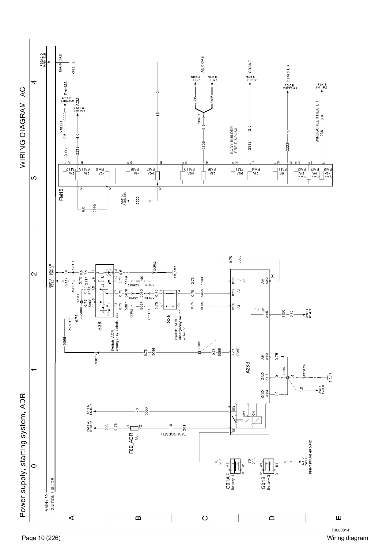
Full schematics for the battery-side power distribution board, UADR (without ADR adaptation) and ADR (ADR-adapted) variants of the FE (3), including the main 30 and 15/DR feeds, the ignition/starting switch logic, ADR emergency switch circuits inside the cab (S38) and outside (S39), and the ADR battery main switch control unit A28B. The ADR alternator relay control, ADR main switch closing request and key-inserted information lines are all drawn with their wire numbers and destination coordinates.
Power Supply, Starting System ADR
The dedicated ADR power supply and starting diagram shows battery G01A and G01B, the starter motor M04, alternator G02A, the fuse F89.ADR (1A) and fuse FM15 group, the ADR alternator relay K51B, and every feed to the ACM and auxiliary circuits with their connector terminations.
Power Take Off and Gearbox Area
Two pages of power-take-off wiring cover the PTO switch logic (S28A power take off), gearbox-area switches, the reverse gear switch S49, the neutral position switch S90, the solenoid valves for PTO 1, 2 and 3 (Y18G, Y18X, Y18L1) and the PTO feedback position switches (S124C, S124G, S124J). The mechanical and robotised gearbox area is broken out for both PTO 1 and PTO 2 on the GI021 gearbox interface, including mechanical gearbox, I-shift mechanical and Allison 3000 automated transmission notes.
Air Power Management (BBOX-L) and Air Heater ADR
The air power management diagram shows the control unit A63 with its front brake, rear brake, trailer brake, parking brake and info inputs, the pressure switches, and the KL15/KL31 feed terminals. The air heater ADR diagram covers the control unit A32C, the parking heater control S151 and switch S21A, the auxiliary pump feedback, and the fuel dosing pump Y32 with its K-line and dosing pump heater feeds.
Electronic Steered Axle
The electronic steered axle diagram (A59 rear axle steering control unit) includes the steering angle sensors B49F (front) and B49R (rear), the oil level sensor B10B, the solenoid valve block Y53 with cut-off valve, steering axle and right-hand curve outputs, and the J1587 and J1939 data links to the rest of the truck.
Body Builder Connector PB4
A dedicated page for the body builder connector PB4 shows PTO 1/2/3 requests, PTO 1/2 valves and feedbacks, engine start and engine start allowed, BBM ECU interface, engine warning, free programmable outputs and the J1939 CAN high/low pins — the exact interface an upfitter needs when integrating body equipment.
CAN J1587-1 Data Bus
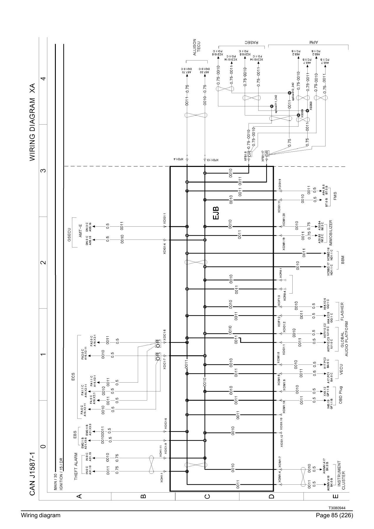
The CAN J1587-1 overview page maps the entire data-bus backbone across the vehicle, showing the EJB backbone, ECS, EBS, theft alarm, instrument cluster, body builder module, audio platform, GSEUC, FMS, Allison TECU, immobiliser, BB2 and OBD-II plug, with the high and low lines and their connector destinations clearly labelled.
12 V Power Supply
The 12 V power supply diagram covers the voltage converters U06R10 (10A) and U06R15 (15A on header shelf), the sockets X22D (24V), X23 (24V accessories), X24D, X44 (24V cubic storage), the pack office A101, citizen band unit A73, and the 24V/12V conversion paths used for cab accessories and cab phone chargers.
Illustrations and Wiring Harness Layouts
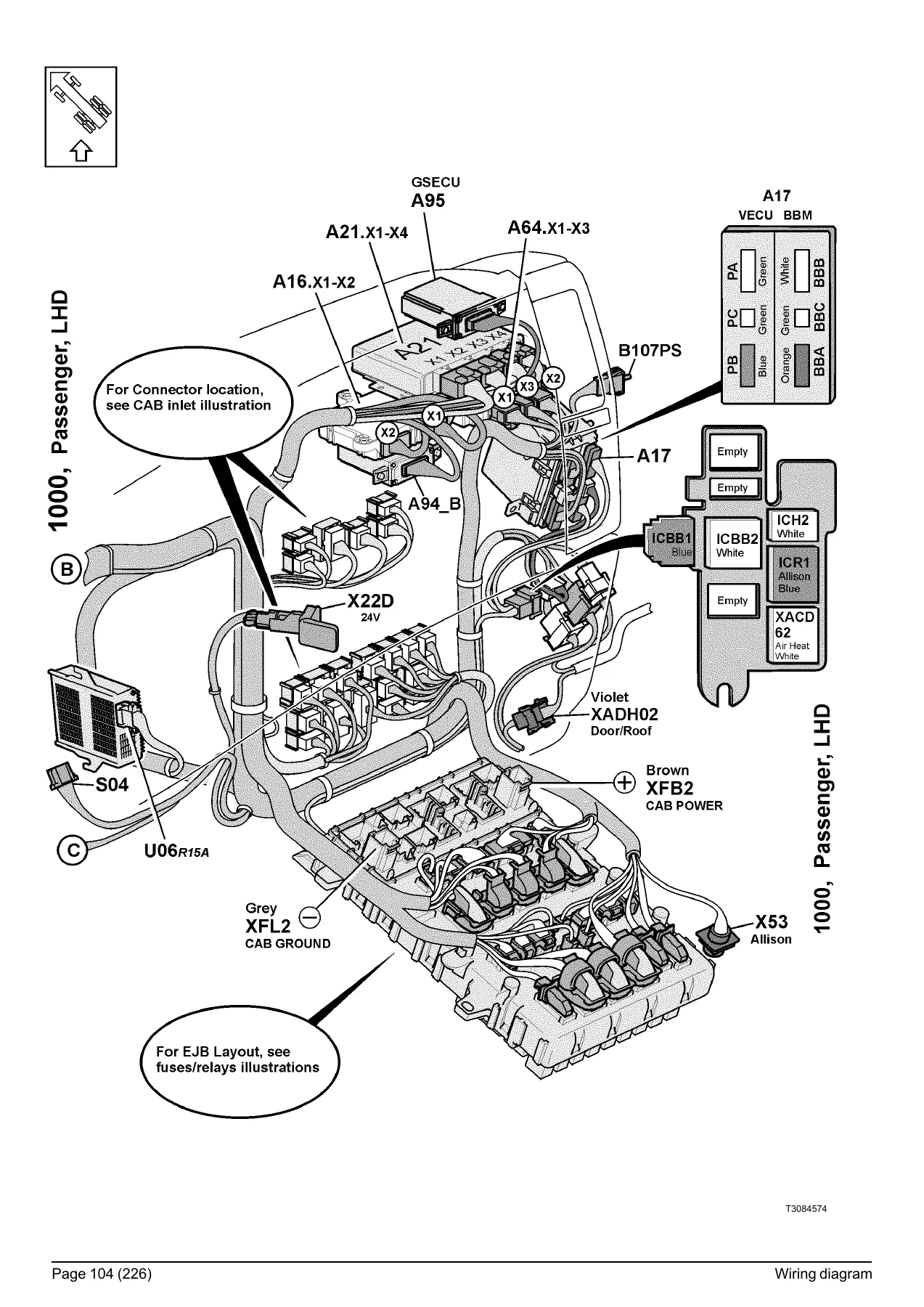
Beyond the schematics, the manual contains a full set of physical harness illustrations so you can locate a connector by sight rather than by guessing from a diagram. Each harness is drawn as it is routed in the truck, with every plug, splice, ground eyelet and branch tagged with its component designator. Harnesses covered include:
- 1000 — cab instruments, driver LHD, driver RHD, passenger LHD, passenger RHD, steering wheel
- 1006 — roof harness, LHD and RHD
- 1007 — floor harness, LHD and RHD
- 1030 — engine harness, D8 EM-EU6
- 1040 — frame harness, front, rear rigid, rear tractor, rear TAG
- 1047 — roof beacon light harness
- 1057 — chassis harness, EASPS, ADTP-R, EM-EU6
- 1063 — trailer connections harness
- 1077 — trailer harness variants
- 1083 — door harness
- 1435 / 1460 — main switch, cab-battery box
- 1447 — bumper harness
- 1494 — gearbox harness
- 1501 — upper front harness
Fuses, Relays, Grounds, Connectors and Components
The reference tables at the back of the book turn the diagrams into a working tool. The fuse list gives the position, rating and function of every fuse from F65 through F109 plus the FM15 main fuse group in the battery box. The relay list identifies each relay by designator and function, from K01 (engine preheater / park brake trigger) through K51B (manual circuit breaker), including the junction box relays K01_P through K28. The ground connection list documents every ground point on the truck — engine, cab, chassis, frame, predispositions — with its coordinate. The connector list gives pin-by-pin circuit function, wiring number and diagram coordinate for the major connectors (ICBB1, ICR1, PB3, X02, X03, X22D, X23, X24D, X26, X35, X43, X44, X45, X53, X56R/T, X58R, X59T, X62, X66, X67, XC301, XC302, XC303, XC304, XC306, XC307, XC309, XC310, XC322, XCBB1, XCH1/2/3, XCI1–XCIO2, XCIS1–XCIS3, XCR4–XCR12, XCRH, XFL1/2, XFT1, XT65, YCF1, YCF2, YFB1/2, YFD1/2, YFF1/2, YFL1, YFRA1/2, YFT1, YFTP1, and more). The wiring number list indexes every wire from 1 to 8189 to its diagram coordinate, and the component list identifies every module, sensor, switch, lamp, motor, solenoid and antenna with its location in the book.
Who This Volvo FE (3) Wiring Diagram Manual Is For
This PDF is written for the working technician, the fleet electrician and the body builder integrating equipment onto an FE (3) chassis. It is the document Volvo produced so that a fault in a lighting circuit, a starting circuit, the ADR system, an air heater, a PTO valve or an electronic steered axle can be traced to a specific wire and a specific pin. It is equally useful to a workshop that needs the correct fuse rating, the correct relay function or the correct ground point before touching a customer’s truck. Body builders get the body builder connector pinouts and the CAN bus assignments they need to interface aftermarket equipment without cutting into the wrong circuit.
Volvo FE (3) Electrical Diagnostics Without Guesswork
Electrical faults on a modern Volvo truck rarely come down to a single broken wire. They come from a connector that has backed out of its housing, a ground eyelet that has corroded, a relay that has failed, or a signal that is being pulled low on the J1939 or J1587 data link. Guessing at a circuit costs hours — and on an ADR-adapted FE (3), a wrong splice can disable the truck’s ADR compliance. The wiring diagram manual removes the guesswork. You see the exact wire number, its cross-section, its connector, its pin and the diagram coordinate on the next page so the trace is unbroken. You see where the splice is, where the ground returns, and which module owns the signal.
What makes this edition worth having on the laptop is that it is drawn for the specific chassis ID prefix B669378- and the September 2013 build date. It matches the FE (3) as Volvo built it, with the ADR, UADR, EU6 D8 engine harness and the post-2013 electrical architecture all documented. The fuse and relay charts in the back are laid out by position so you can read them at the battery box, and the illustrations show you what the harness actually looks like on the truck rather than making you translate a schematic into a physical layout in your head.
Delivery is instant. After checkout you receive the PDF immediately — no shipping, no waiting on a workshop library request. Open it on a laptop, a tablet or a phone in the workshop, print the schematics you need for the bay, and keep the full manual on file for the next FE (3) that comes in. One purchase, every diagram, every fuse, every ground, every harness — the same electrical documentation Volvo Truck Corporation published under order number 89137094.
IMAGES PREVIEW
Reviews
There are no reviews yet.