
Volvo VM EM-EU5 Truck Wiring Diagrams Manual 89250692 Release 02 – PDF Download
Original price was: $44.95.$29.95Current price is: $29.95.
Complete Volvo VM EM-EU5 wiring diagrams manual, order number 89250692, Release 02. Covers chassis electrical schematics, fuse and relay lists, connectors, components and cable colour codes for CHID E156615- trucks.
Description
Volvo VM EM-EU5 Wiring Diagrams Manual – 89250692 Release 02
This is the complete Volvo wiring diagram manual for the VM truck with the EM-EU5 electrical system, issued under order number 89250692, Release 02. It covers vehicles from chassis ID CHID E156615- and includes the full set of electrical schematics, fuse and relay listings, connector pin-outs, component locations and cable colour codes used on these trucks.
Every circuit is presented with wire colour and cross-section identifiers, connection point references and coordinate call-outs, so you can trace faults, verify pin-outs and confirm component function without guessing. The manual was originally published by Volvo Truck Corporation, Curitiba, Brazil in 2014, and this edition reflects the designs and methods studies carried out up to May 2014.
File Details
- Manual type: Wiring diagram manual
- Brand: Volvo
- Model / variant: VM, EM-EU5
- Chassis ID range: CHID E156615-
- Order number: 89250692
- Release: 02
- Publication date: May 2014
- Language: English
- Page count: 111
- File format: PDF
Chapters Covered
- Contents of wiring diagrams
- Wiring diagrams
- Illustrations index
- Illustrations
- List of fuses
- List of relays
- List of connectors
- List of components
- Colour codes of electrical cables
Wiring Diagrams
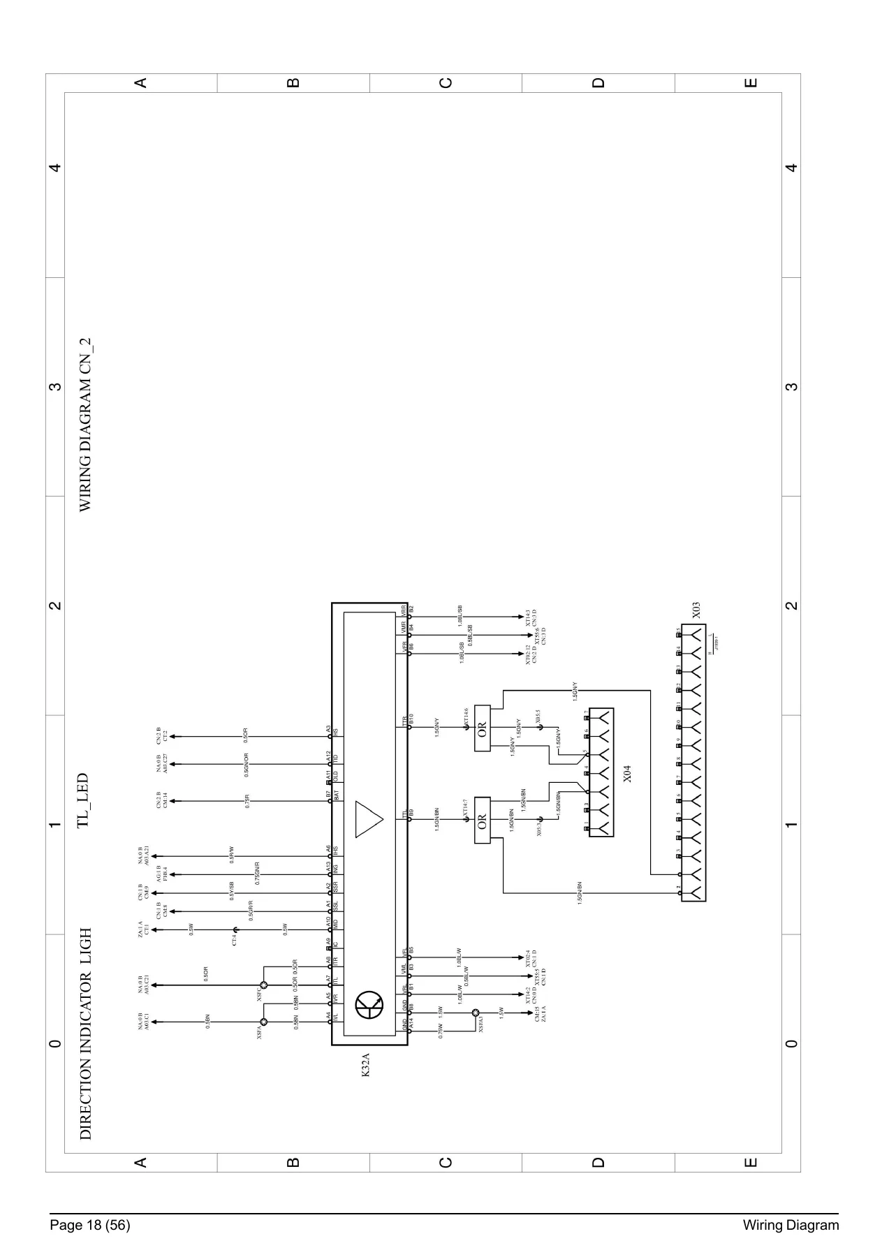
The main body of the manual is the wiring diagram set, using the standard Volvo legend (title of wiring diagram, variant/subtitle, symbol, coordinates, battery voltage +, +30 voltage with S12 key, +DR voltage with ignition switch in driving, preheating or starting position). Individual diagram sheets cover the systems used on the VM EM-EU5 truck, including gateway / OBD, direction indicator light, SCR (FAA20), 12V power supply, exhaust brake, differential lock (including 6×4), horn, range / area inhibitor, bogie lift rear, air cooler, Eaton gearbox, instrumentation, tachograph and earth connections. Each page uses the same connection-point, fuse, relay, switch, cable section and colour conventions shown in the opening explanation pages, so you can move between diagrams without re-learning notation.
Illustrations and Component Locations
This section contains the pictorial harness drawings referenced by the wiring diagrams. It shows the physical layout of harnesses and connectors across the truck: instrument panel connectors (XJE21, XJB15, XJR13, XJR14, XJF01, XJR11, XT02, XT12, XT14, XT22, XT32, XT33, XT42, XT54, XT55, XT56, XT62), steering wheel switch connectors (S15, S30, S02A, S02, S06, X35), bumper harness layouts for BUM-PP, BUMP5 and BUMP5 variants (XJF01, XT02, H09, H01, E07R, E07L, E30R, E30L, E30RS, E30LS, E13RF, E13LF, E03R, E03L, XC322, XC323), rear lighting for TRACTOR and RIGID (XJR11, XT14, XJR13, XT55, XT42, XJB15, E27L, E27R, X05, X02, X04), fuel tank sensor and brake pad wear (XT42, XT55, B07, B41A, B40A, B133, S41, S43, S71, B60A, B06B, Y01, Y27, Y05, B60B, S117, Y02, Y05A, E13RS), ABS layouts for 4×2, 6×4, 6×2, 8×4 and 8×2 (XT54, XT56, B13A, B14A, B15A, B16A, Y11, Y12, Y13, Y14), gearbox harness routing for VT214B, VT2214B, F1109, F16108LL, F095068, F0909506A and F076060A (B12, S49, Y06, S47, S63, GA, GB, GA2, GB2, Y18G, A13E, Y18A), I-Shift cab-to-gearbox harness (XJE21, GA2, GB2), cab front (XT62, M01) and ADTR50 / ADTR95 AdBlue tank installations (XT32, B96, B97, B143, R36, R23J, R23G, R23H, R23E, R23C, R23A, R23D, Y80, Y81, A62). Use these pages to locate the physical connector or component before you begin testing.
Fuses and Relays
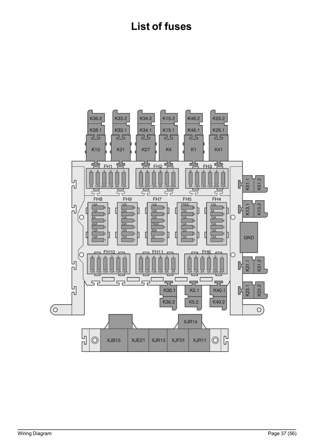
The fuse section shows the complete fuse layout with FH1 through FH11 fuse groups and their individual circuits. Fuse group FH1 covers control unit EDC, tracking system / trailer brake, ABS brake system, air conditioning system, tachograph / engine brake / gateway, and OBD. FH2 covers fuel pre-heater, load sensor / power take-off, gear selector control unit and lifting of 3rd axle (6×2) and 2nd front axle (8×2), step-down gear / urea system control unit, air conditioning system and climate unit. FH3 covers windshield wipers, auxiliary fuel heater, ABS body builder, rear view mirror defogger, and trailer brake / brake light relay / reverse lamp relay. FH4 covers bending light, door locking, interior light, horn, fifth wheel light and reverse lamp. FH5 covers Dynafleet, Eaton gearbox and instrument cluster. FH6 covers ABS body builder, ABS brake system, fifth-wheel lamp relay, air horn and 12V converter. FH7 covers gateway, control unit EDC, starting switch, climate unit and daytime running lamps. FH8 covers 12V converter, tail lamp LED, electric windows, Dynafleet, dipped beam left and dipped beam right. FH9 covers tachograph / hazard lamps, tracker, urea system, door lock, I-Shift gear selector and I-Shift transmission control unit. FH10 covers full beams, front fog light, brake lamp, rear fog lamp and left/right full beam. FH11 covers position light, cluster light, left/right parking lamp, trailer position light and Dynafleet. The relay list documents each relay location and function, including starting switch accessories, starting motor, I-Shift, load sensor, power supplies X/Y/Z, alternator, low split solenoid valve, horn, low beam / spot light, parking lights trailer / body builder, flasher unit, full beams, interior parking lights, daytime running lamps, pole change, heated adjustable mirror and starter motor, reverse light, rear fog lamp, climate fan speed, PTO circuits, engine pre-heater, windscreen wiper timer, PTO signal for I-Shift, air conditioning signal for I-Shift and PTO external control.
Connectors and Components
The connector and component lists give the full reference for every plug, sensor, switch and actuator shown in the wiring diagrams. Entries include the connector code, the diagram coordinate it appears on, and the pin assignments. Examples include GND connections, X05, X21C, X35, XACD61, XACD62, XACH01, XACH02, XC322, XC323, XGND3, XJB18, XJE21, XJF01, XJR11, XJR12, XJR13, XJR14, XJR80, XSA through XSX and XT-series connector groups. Component listings cover switches (S02A, S04, S06, S07, S08, S08A, S09A, S11, S11A, S15, S19, S28A, S30, S41, S43, S44-L, S44-R, S45, S45A, S45B, S47, S47A, S48, S49, S58B, S61, S63, S71, S76A, S77, S90, S103, S103B, S105, S106_DD, S106_DP, S107, S117, S117A, S152, S171, S196), diodes (V01 through V28), antennas (W06, W12), trailer connections (X02, X03, X04, X07, X54), and solenoid valves (Y01, Y02, Y02A, Y03A, Y05, Y05A, Y06, Y06A, Y11, Y12, Y13, Y14, Y18, Y18A, Y27, Y31, Y41L, Y41R, Y52, Y80, Y81). The colour code section at the end of the manual lists cable colours and the two-colour notation used throughout: BL (blue), BN (brown), GN (green), GR (grey), OR (orange), P (pink), R (red), IS (black), VO (violet), W (white), Y (yellow), with two-colour cables marked like Y/R for Yellow/Red.
Why This Volvo VM EM-EU5 Wiring Diagram Manual Matters
Electrical faults on a modern commercial truck are rarely solved by swapping parts. You need to know which wire feeds which pin, where the connection point sits, and which fuse or relay protects the circuit. This manual gives you that information in the same format the truck was built to. Whether you are diagnosing a non-starting VM, tracing an intermittent indicator fault, checking an ABS sensor circuit, or verifying AdBlue heater wiring, the schematics let you follow the current path from battery to earth, confirm continuity at the correct connector pin and rule out the wiring before you condemn a control unit.
The illustrations section is equally practical for hands-on work. Being able to see that a harness runs behind a specific panel, that a connector sits at a particular chassis location, or that two variants of the same circuit use different connector codes saves hours of searching. When you are working on a fleet vehicle or a truck that has already been modified, having the original factory routing and connector references is the difference between a quick repair and a comeback.
Who This Manual Is For
This Volvo VM EM-EU5 wiring diagram manual is intended for technicians, auto electricians, fleet maintenance workshops and owners who need to service or repair the electrical system on VM trucks built to the CHID E156615- specification with the EM-EU5 electrical architecture. It covers the full range of chassis configurations referenced in the manual, including 4×2, 6×2, 6×4, 8×2 and 8×4, and the gearbox and driveline variants documented in the illustrations (Eaton, I-Shift, VT214B, VT2214B, F1109, F16108LL and others). The electrical architecture is shared across these configurations, so the same schematic page can be used to troubleshoot several different truck build specifications.
Because the manual includes both the schematic symbols used for switches, relays, printed circuit board conduction paths, earth connections and connectors, and the physical harness routing drawings, it works as a standalone reference for any electrical job on these vehicles. You do not need additional reference material to interpret the diagrams.
IMAGES PREVIEW
Instant PDF Delivery
The manual is delivered as a PDF download immediately after purchase. There is no shipping, no waiting for a disc or binder, and no risk of a lost parcel. The file can be opened on a laptop, tablet or smartphone in the workshop, and individual pages can be printed and taken to the truck when you need a paper copy under the bonnet. If you are repairing a Volvo VM EM-EU5, having the complete wiring diagram manual on hand means you can confirm the circuit, find the connector and finish the job correctly the first time.
Reviews
There are no reviews yet.