
Volvo Penta TAD134X TAD135X TAD136X TAD137X TAD138X Workshop Manual Groups 21-26 – PDF
Original price was: $39.95.$24.95Current price is: $24.95.
Complete Volvo Penta workshop manual for the TAD134X, TAD135X, TAD136X, TAD137X and TAD138X VE/GE six-cylinder diesel range, covering Groups 21-26 plus the alternator. Engine strip-down, cylinder head, pistons, valve mechanism, timing gears, crank mechanism, lubrication, fuel, inlet and exhaust, and cooling repair procedures with tightening torques and special tools.
Description
The Volvo Penta TAD134X TAD135X TAD136X TAD137X TAD138X Workshop Manual Groups 21-26 is the full engine workshop documentation for the 12.78-litre six-cylinder Volvo Penta industrial diesel range, issued under publication number 7748841, edition 07-2020. It carries Groups 21 through 26 together with the alternator group, and it walks a qualified technician from exposing and lifting the engine out of its installation, through complete disassembly, measurement and overhaul, right back to assembly, adjustment and final function checks. Every operation is presented with numbered illustrations, staged torque-and-angle tightening sequences, special tool references and wear limits taken from the engine specification chapter.
File Details
- Manual type: Workshop Manual (service, repair and overhaul)
- Brand: Volvo Penta
- Covered designation: TAD134X GE/VE, TAD135X GE/VE, TAD136X VE, TAD137X VE, TAD138X VE
- Publication number: 7748841
- Edition / date: 07-2020
- Language: English
- Page count: 338 pages
- File format: PDF
Groups and Chapters Covered
- General Information — general, miscellaneous
- Specifications — general specifications, engine specifications, technical data, electrical specifications
- Safety and Other Instructions — safety instructions
- Special Tools — special service tools and other equipment
- General 20-0 — engine information, troubleshooting, test and adjustments
- 21-0 Engine Complete, General — exposing the engine, fitting the fixture, engine disassembly, engine assembly
- 21-1 Cylinder Head — removal and installation
- 21-3 Cylinder Liner, Pistons — liner and piston inspection, connecting rod check
- 21-4 Valve Mechanism — valve and unit injector adjustment, valve guides, valves, valve seats, valve stem sealings
- 21-5 Timing Gears and Shaft — camshaft wear check, camshaft bearing housing, flywheel indication, gear ring replacement, sensor adjustment
- 21-6 Crank Mechanism — crankshaft seals front and rear, crankshaft inspection, main bearing change
- 22-1 Oil pump and Line — lubrication oil pump change
- 22-2 Oil filter — oil pressure sensor check, oil filter bracket change, safety valve, bypass valve
- 22-3 Oil cooler — oil cooler replacement, thermostat oil cooler change
- 23-0 Fuel System, General — fuel system bleeding, draining the fuel duct in the cylinder head
- 23-3 Fuel Feed Pump and Filter — fuel feed pressure check, fuel filter housing change, fuel feed pump change
- 23-7 Injectors and Delivery Pipes — unit injector replacement, injector change, injector sleeve replacement, common rail change, pressure pipe replacement
- 23-8 Control System, ECM, Data Sets — control unit replacement
- 25-0 Inlet and Exhaust System, General — charge air pipe leakage check
- 25-1 Inlet and Exhaust Manifolds — intake manifold change
- 25-4 Emission Control, Catalytic Converter — e-EGR control valve change, EGR mixing chamber change
- 25-5 Turbo and supercharger — turbocharger inspection, turbo change
- 25-6 Air Cleaner, Throttle Housing — air throttle change
- 26-0 Cooling System, General — draining, cleaning, coolant level, pressure testing
- 26-2 Coolant Pump, Thermostat — coolant pump change, thermostat change, drive belts, belt tensioner, thermostat function check, coolant filter change
- 26-3 Fan, Fan Shroud — belt guards
- 32-1 Alternator — alternator belt replacement, belt tensioner change
- Index and References to Service Bulletins
Taken as a whole, this is a genuine overhaul manual rather than a routine maintenance booklet. It assumes the engine is out of the machine and mounted on a stand, then documents each system to the level of individual bearing shells, valve guides, injector sleeves, thrust washers and gear lash measurements. Where a job can also be done in situ, the same working method is given with the appropriate precautions noted, so the manual works for both a full rebuild and a targeted repair.
What the Engine Sections Give You
The engine group is the core of the document. Disassembly begins with draining coolant and oil, removing the fuel connections, radiator hoses, air filter and turbocharger pipework, then fitting the lifting equipment and mounting the block on the fixture. From there the timing gear cover comes off, the gears are removed and inspected, the cylinder head is lifted away, liners and pistons are drawn out, and the crankshaft is lifted once the main bearing caps are released. Assembly reverses the process with the timing marks, gear lash settings and bearing clearances spelled out at each stage.
Cylinder head work is treated in depth. The manual covers rocker arm bridge removal with the lifting tool, camshaft removal and refitting with the bearing cap sequence, unit injector extraction and refitting with new steel washers, valve yoke marking, valve and injector adjustment for the standard mechanism as well as the VCB (Volvo Compression Brake) and internal EGR variants, and valve guide and valve seat replacement with heating and cooling instructions.
Bottom-end work covers cylinder liner removal and refit with the liner height measurement above the block plane, piston and connecting rod removal and installation, connecting rod straightness and twist checks, crankshaft inspection, and main bearing shell replacement with the crankshaft left in the engine block. Front and rear crankshaft seal replacement is documented separately for the earlier and later production versions, including the setting diameters for the seal pullers and mounting tools.
Fuel, Lubrication, Air and Cooling Systems
Fuel system coverage centres on the unit injectors, the injector sleeves, the common rail unit on the TAD1381VE through TAD1385VE engines, and the pressure pipes. Injector yoke tightening is given in staged torque-plus-angle steps, and the manual is explicit that the steel sealing washer is replaced every time an injector is fitted. Fuel feed pump replacement, fuel filter housing replacement, fuel feed pressure checking and fuel system bleeding are all covered, along with draining the fuel duct in the cylinder head before compression testing.
The lubrication group documents the oil pump, suction strainer, delivery and connection pipes, the reinforcement plate, the oil filter bracket, the oil pressure safety valve and the oil filter bypass valve, plus oil pressure sensor checking against the specified values. The oil cooler section covers cooler replacement, cover resealing and the thermostat oil cooler.
Inlet and exhaust coverage includes intake manifold replacement with the guide pins and sealant groove, exhaust manifold tightening in stages and sequence, turbocharger inspection for compressor wheel damage, end float and oil carry-over, turbo replacement for both the earlier and TAD1381VE-TAD1385VE layouts, and the e-EGR control valve and EGR mixing chamber procedures with their own torque tables. Air throttle replacement and charge air pipe leakage checking complete the group.
Cooling system work covers draining, internal cleaning and flushing, coolant level checking and topping up, pressure testing using three different tool arrangements, coolant pump replacement, thermostat replacement for two housing layouts, drive belt and belt tensioner work, and coolant filter replacement.
Tightening Torques, Specifications and Special Tools
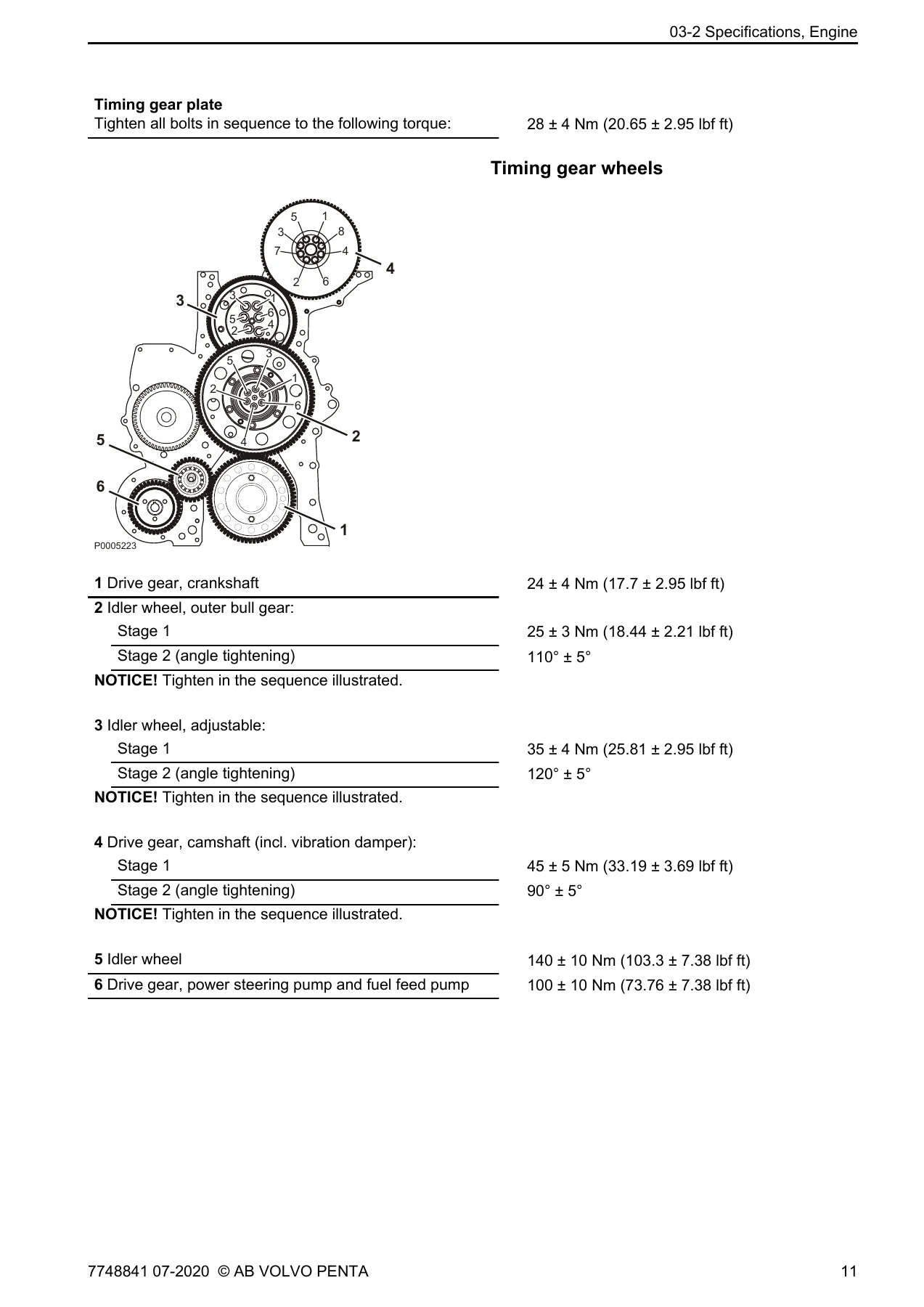
A dedicated special tightening torque section collects the figures that matter most. It lists the front engine mount stages, main bearing cap and big end bearing cap stages, the frame reinforcement sequence for bolts 1 to 24, timing gear plate and timing gear wheel torques, flywheel housing, flywheel, vibration damper, crankshaft seal cover, cylinder head, camshaft and rocker arm shaft stages, valve cover, oil sump, oil cooler, unit injector yoke, fuel line brackets, intake and exhaust manifolds, turbo and V-clamp values. General tightening torques for M6 through M16 fasteners are given separately.
The engine technical data chapter supplies the bore, stroke, swept volume, injection sequence, compression ratios by engine variant, low and high idle speeds, dry and wet weights, overall dimensions, cylinder head bolt dimensions and count, liner sealing surface height, piston ring clearances and end gaps, valve head and stem dimensions, valve seat angles and depths, valve guide data, valve spring dimensions, camshaft bearing journal diameters including undersizes, crankshaft main and big end journal diameters and undersizes, thrust washer and bearing shell thicknesses, connecting rod dimensions, flywheel and flywheel housing runout limits, oil capacities and pressures, oil temperature limits, filter quantities, fuel feed pressures, bypass valve opening pressure, pressure drop indicator value, cooling system pressure cap value, thermostat opening temperature and coolant quantities.
The special tools chapter lists the tool numbers used throughout the procedures, from lifting tools, fixtures and adapters through pullers, drifts, guide sleeves, press tools, the compression meter, the dial indicator sets, the timing tools, the pressure testing kits and the injector cleaning kit. Safety instructions are provided in their own chapter, and the sensor location chapter identifies the position of the charge pressure, oil pressure, crankcase pressure, coolant level and temperature, fuel pressure, flywheel and camshaft position sensors.
Who This Manual Suits
This Volvo Penta TAD134X TAD135X TAD136X TAD137X TAD138X workshop manual is aimed at the technician working on a stripped engine in a properly equipped workshop. It assumes familiarity with mechanical and electrical trade practice, access to the listed special tools, and the ability to work to stated tolerances. Because the procedures reference the exact tightening sequences and measurement values for these engine variants, it removes the guesswork from a rebuild and gives a clear basis for deciding whether a component can be reused, machined to an oversize, or replaced.
Get the Full Groups 21-26 Workshop Manual
With this manual on hand you can strip and rebuild the engine, replace cylinder heads and liners, set valve and unit injector clearances on the standard, VCB and internal EGR valve mechanisms, rebuild the bottom end, overhaul the lubrication, fuel, air and cooling systems, and reinstall the turbocharger and EGR components with the correct torque and angle values rather than approximations. That means fewer comebacks, fewer damaged components from incorrect sequences, and a rebuild that holds together.
IMAGES PREVIEW
The manual is delivered as an instant PDF download after payment, with no shipping and no waiting. Read it on a laptop, tablet or phone in the workshop, search it for the group you need, and print the pages you want to take to the engine. It is the practical reference for anyone servicing, repairing or overhauling a Volvo Penta TAD134X, TAD135X, TAD136X, TAD137X or TAD138X industrial diesel.
Reviews
There are no reviews yet.