
Wärtsilä Vasa 6L32 Instruction Manual – Complete Engine Workshop & Maintenance PDF
Original price was: $49.95.$29.95Current price is: $29.95.
Full Wärtsilä Vasa 6L32 instruction manual (engine PAAE051728) covering operation, maintenance schedules, adjustments, clearances, overhaul, injection system, turbocharging, cooling water, control mechanism and WECS 2000 automation. Instant PDF download for marine and power plant engineers.
Description
Wärtsilä Vasa 6L32 Instruction Manual – Complete Engine Workshop & Maintenance PDF
The Wärtsilä Vasa 6L32 Instruction Manual is the full works instruction book for the Wärtsilä Vasa 6L32 medium-speed diesel engine, issued under engine number PAAE051728. It covers operation, maintenance, adjustment, overhaul and troubleshooting in the depth required by marine engineers, power plant technicians and workshop crews who service Wärtsilä 32 series engines. Because the Wärtsilä 32 family shares a common design language – identical 320 mm bore, 400 mm stroke, underslung crankshaft, hydraulically tensioned main bearings, unit injection pumps or common rail injection, and the same WECS 2000 automation platform – the procedures also apply directly to the 8L32, 9L32, 12V32, 16V32, 18V32 and 20V32 variants.
File Details
- Manual type: Engine instruction / workshop manual
- Brand: Wärtsilä
- Engine type: VASA 6L32
- Engine number: PAAE051728
- Language: English
- Format: PDF (digital download)
- Scope: Operation, maintenance, overhaul, adjustment and troubleshooting of the Wärtsilä 32 series engine
Chapters Covered
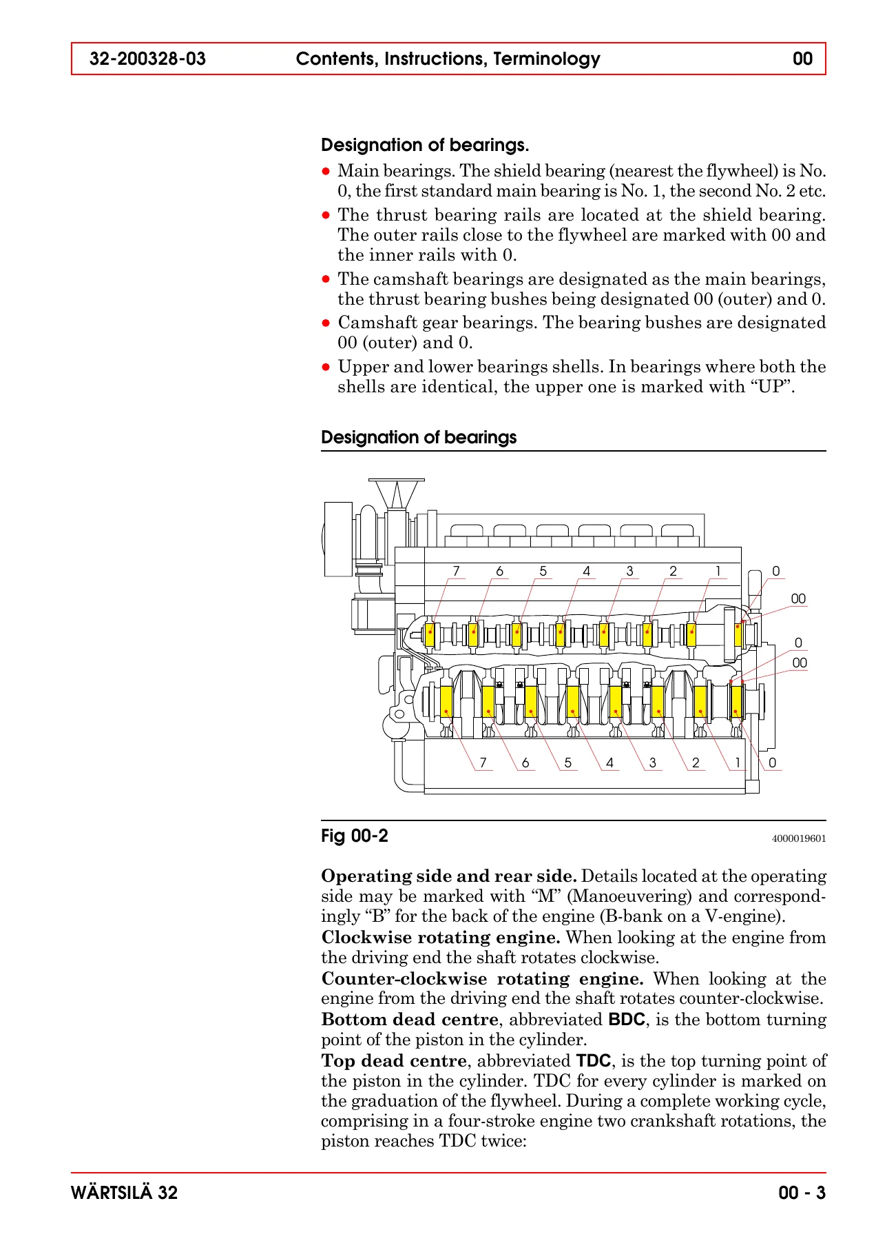
- 00. Contents, Instructions, Terminology – contents of the manual, general rules, terminology, cylinder and bearing designation, flywheel marking
- 00A. Risk Reduction – general hazards, leakage, electrical and assembly hazards, personal safety equipment
- 00B. Welding Precautions – welding safety, preventing current loops, radiation and spark damage, ECU / WECS 2000 / WECS 3000 / WECS 7000-8000 / UNIC checklists
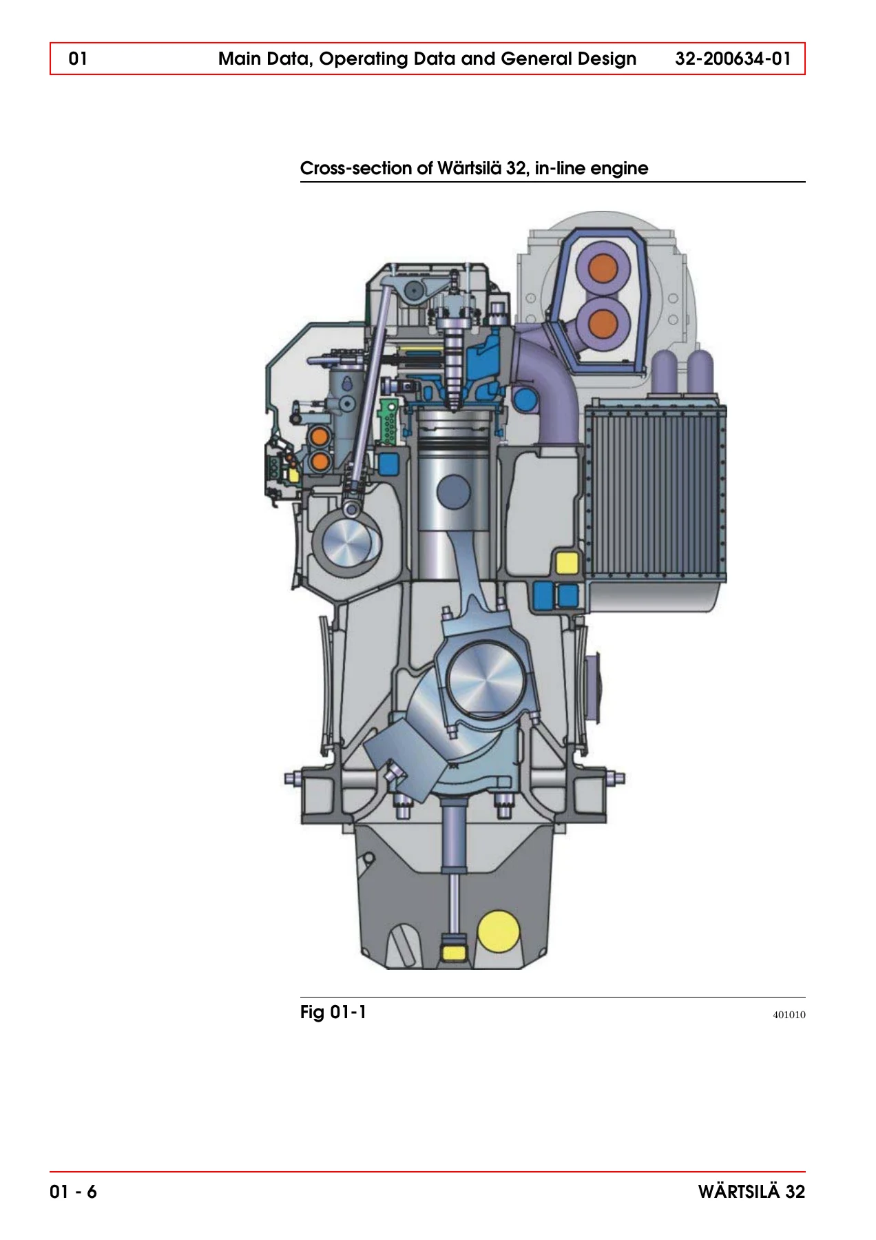
- 01. Main Data, Operating Data and General Design – engine data, firing orders, lubricating oil and cooling water volumes, recommended operating data, reference conditions, general engine design
- 02. Fuel, Lubricating Oil, Cooling Water – fuel viscosity limits, purification, heating, viscosity control, maximum fuel characteristics, CCAI, lubricating oil qualities, BN requirements, cooling water treatment and additives
- 02A. Environmental Hazards – fuel oils, natural gas, lubricating oils, cooling water additives, fly ash, lead in bearings, fluoride rubber products, first aid
- 03. Start, Stop and Operation – turning of crankshaft, local and remote start, emergency start, manual stop, normal operation supervision, running-in programme
- 04. Maintenance Schedule – daily, weekly, 50 h, 100 h, 500 h, 1000 h, 2000 h, 4000 h, 8000 h, 12000 h, 16000 h, 24000 h and 48000 h intervals
- 05. Maintenance Tools – main bearing, cylinder liner, connecting rod, cylinder head, injection equipment, intermediate gear and camshaft tools, measuring and testing equipment
- 06. Adjustments, Clearances and Wear Limits – valve timing, valve clearances, tripping speeds, clearances and wear limits table
- 07. Tightening Torques and Use of Hydraulic Tools – torque tables A to K, locking fluids, hydraulically tightened connections, hydraulic tool safety
- 08. Operating Troubles, Emergency Operation – troubleshooting table, operation with defective air cooler, turbocharger, cams, removed piston and connecting rod, torsional vibrations
- 09. Specific Installation Data – marine and power installation data references
- 10. Engine Block with Bearings, Oil Sump and Cylinder Liner – main bearings, flywheel/thrust bearing, cylinder liner removal and mounting
- 11. Crank Mechanism: Crankshaft, Connecting Rod, Piston – counterbalancing, crankshaft alignment, thrust bearing clearance, connecting rod and piston overhaul
- 11B. Piston Overhaul – piston crown, piston skirt, crack detection, measurements, reconditioning
- 12. Cylinder Head with Valves – description, removal and mounting, valve clearance adjustment, exhaust and inlet valves, seat rings, indicator valve, cylinder tightness testing
- 13. Camshaft Driving Gear – intermediate gears, camshaft gear, basic valve timing adjustment, crankshaft split gear wheel
- 14. Valve Mechanism and Camshaft – valve mechanism, camshaft, camshaft bearing bush removal and mounting
- 15. Turbocharging and Air Cooling – turbocharger maintenance, water cleaning of turbine and compressor, damaged turbocharger operation, charge air cooler
- 16. Injection System – injection pump, maintenance and adjustment, injection pump overhaul, erosion plugs, injection line, injection valve, booster unit, pneumatic overspeed trip device
- 17. Fuel System – functional description, maintenance, venting, adjustments of fuel feed system, start and stop
- 18. Lubricating Oil System – general design, maintenance, lubricating oil pump, pressure regulating valve, lubricating oil cooler, thermostatic valve, automatic filter, centrifugal filter, prelubricating pump
- 19. Cooling Water System – HT and LT circuits, venting and pressure control, preheating, monitoring, water pump, temperature control system, LT and HT thermostatic valves
- 20. Exhaust System – exhaust manifold, change of expansion bellows
- 21. Starting Air System – description, main starting valve, starting air distributor, starting valve, starting air vessel and piping, pneumatic system, slow turning device
- 22. Control Mechanism – description, maintenance, check and adjustment of stop lever and governor stop position, speed governor, hydraulic governor drive, electro-pneumatic overspeed trip device
- 23. Instrumentation and Automation – WECS 2000, functional description, safety system, monitoring and alarm sensors, functional testing, hardware (MCU, DCU, SMU, Relay Module), software, maintenance and troubleshooting, error codes, emergency operation
Read together, these chapters give a technician the complete working picture of the Wärtsilä 32 engine: how it is designed, how it is started and stopped, how each major assembly is dismantled, inspected, measured and reassembled, what torque and hydraulic pressure each connection requires, which clearances are acceptable and which signal a part must be renewed, and how to diagnose a fault before it becomes a failure. The manual is written for an audience that already understands diesel engine fundamentals, so it does not explain basic principles – it goes straight to the Wärtsilä-specific values, tools and sequences that keep the engine reliable on heavy fuel, distillate fuel or crude oil.
Wärtsilä-Specific Service Data You Can Work From
One of the strongest reasons to keep this Wärtsilä Vasa 6L32 instruction manual on the workshop tablet is the density of engine-specific data it carries. The main data chapter gives the cylinder bore of 320 mm, the 400 mm stroke, the 32.17 litre piston displacement per cylinder, the firing order for the 6L32 in both clockwise and counter-clockwise rotation, the lubricating oil volume for wet sump operation, and the approximate cooling water volume. The recommended operating data tables list normal values and alarm/stop limits for lubricating oil temperature before and after the engine, HT water temperature after and before the engine, LT water before the charge air cooler, charge air in the air receiver, exhaust gas after cylinder, cylinder liner temperature, main bearing temperature, and the corresponding gauge pressures for lubricating oil, HT and LT water, fuel and starting air.
The adjustment chapter fixes the valve clearances at 0.4 mm for inlet valves and 0.8 mm for exhaust valves, states the opening pressure of the fuel injection valve at 600 bar for the conventional system, and gives the electro-pneumatic tripping speeds for both 720 RPM and 750 RPM nominal speed engines under WECS/plant automation and relay-module control. The clearances and wear limits chapter carries the main bearing clearance, thrust bearing axial clearance, camshaft bearing clearances, cylinder liner bore limits, big end bearing clearance, gudgeon pin clearances, piston ring gaps, valve stem clearances, injection pump tappet settings and pump backlash values. The tightening torque chapter gives screw-by-screw torque values for the crankshaft and flywheel, intermediate gear and camshaft, governor drive, cylinder head and multiduct, injection pump, injection valve, water-injection flow fuse, accumulator, piston crown and turbocharger, plus the maximum hydraulic pressures for the cylinder head, main bearing, lateral, connecting rod, counterweight and intermediate gear hydraulic tools.
How to Use This Wärtsilä Vasa 6L32 Manual in the Workshop
The manual is organised so that a planned job can be worked from the maintenance schedule outwards. The schedule is split by operating hours and by fuel category, so a heavy fuel engine running above 75 percent average load follows a different overhaul interval than one below 75 percent, and HFO 1, HFO 2 and DO each have their own piston overhaul intervals. From the schedule the reader is directed into the relevant chapter for the disassembly, inspection, measurement and reassembly procedure, and then into the tools chapter for the special Wärtsilä tooling required – hydraulic cylinders, distance sleeves, pins, stud removers, lifting tools, honing equipment, injection pump testing tools, valve grinding tools, camshaft bearing bush tools and the laser and endoscope measuring equipment listed at the back.
The automation and instrumentation chapter is particularly valuable on engines fitted with the Wärtsilä Engine Control System. It documents the WECS 2000 architecture, the distributed control units and sensor multiplexer units, the main control unit and relay module, the Local Display Unit pages and key functions, the standard sensor set for monitoring and safety, the functional testing of overspeed trips using a signal generator or by running the engine, the pressure transducer and temperature sensor testing procedures, the error codes produced when a measurement or communication fails, and the emergency operation routines including blackout start and shutdown override. For an engineer responsible for keeping a Wärtsilä 32 running, that combination of mechanical and control-system information in one document is what makes this manual the practical reference rather than a shelf ornament.
Why This Manual Matters
Wärtsilä medium-speed engines are unforgiving of improvised procedures. A main bearing tightened to the wrong hydraulic pressure, a cylinder head screw reused after the maximum pressure has been exceeded, an O-ring lubricated with oil instead of soap in the cooling water space, a piston crown refitted without the specified crosswise tightening and angle step, or a fuel injection pump tappet set to the wrong distance can all turn a routine overhaul into a major repair. The Wärtsilä Vasa 6L32 instruction manual exists to prevent exactly that, by stating the sequence, the measurement, the torque, the hydraulic pressure and the wear limit for every step in the job.
IMAGES PREVIEW
Instant PDF Delivery
This is a digital product. After payment the Wärtsilä Vasa 6L32 instruction manual is available immediately as a PDF download – no shipping, no waiting for a printed copy, no customs delay for a workshop that is already alongside. Open it on a laptop in the engine room, on a tablet at the workbench, or print the pages you need for a specific overhaul and let them get oily while the master copy stays clean. Every chapter, table and illustration referenced in this listing is included in the same document, so the engineer, the fitter and the superintendent are all working from the same set of Wärtsilä 32 procedures.
Reviews
There are no reviews yet.