Xerox Phaser 6200 Color Laser Printer Service Manual PDF Download
Original price was: $85.00.$20.95Current price is: $20.95.
Complete Xerox Phaser 6200 color laser printer factory service manual with troubleshooting procedures, error codes, service diagnostics, FRU disassembly/replacement instructions, parts list with exploded views, wiring diagrams, theory of operation, cleaning procedures, and technical specifications for professional printer repair.
Description
Xerox Phaser 6200 Color Laser Printer Service Manual PDF Download
DESCRIPTION:
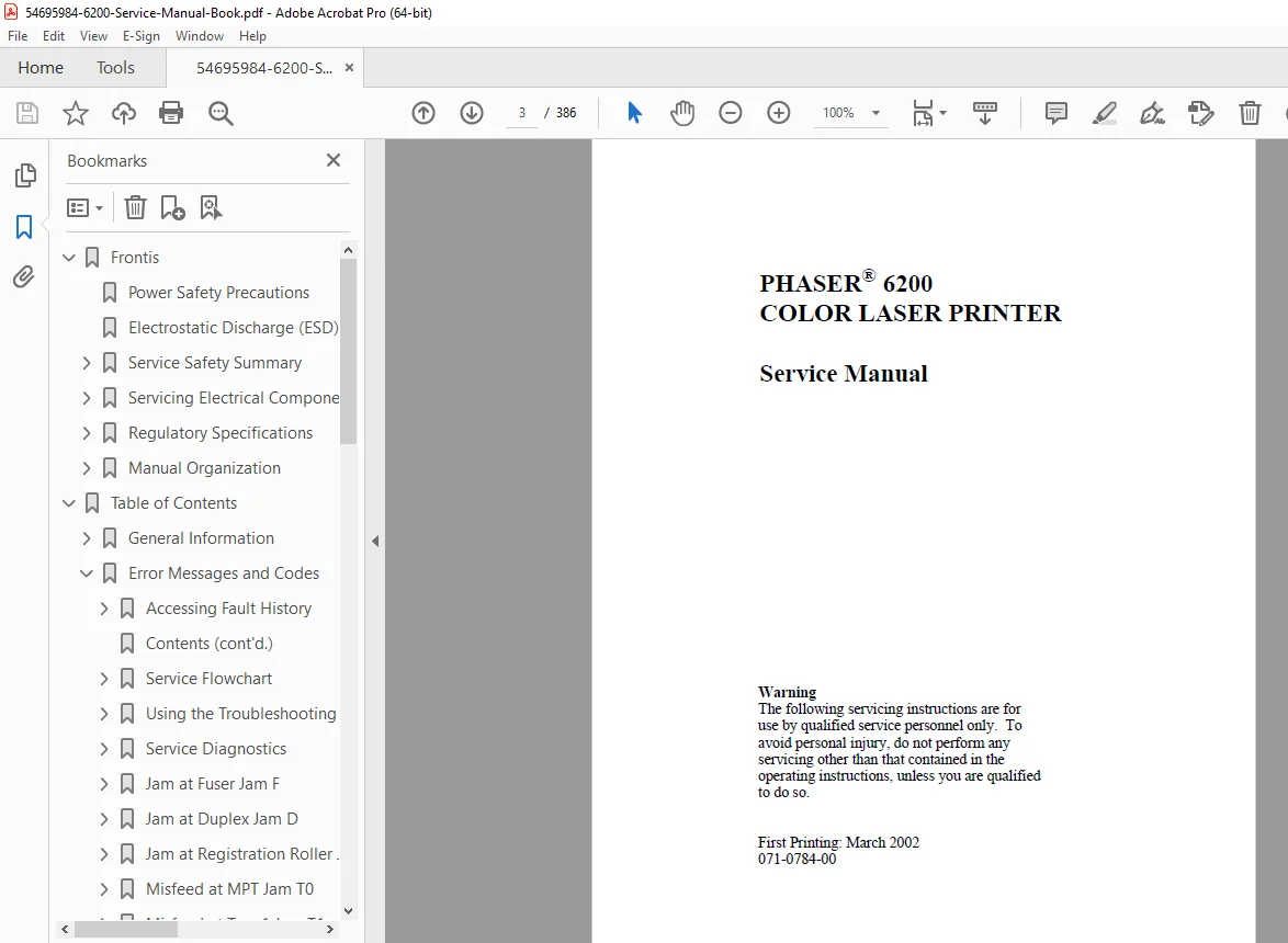
This comprehensive Xerox Phaser 6200 service manual (Publication 071-0784-00, March 2002) provides complete factory technical documentation for servicing and repairing the Xerox Phaser 6200 Color Laser Printer. Essential for authorized Xerox service technicians, independent printer repair specialists, and IT support professionals.
Printer Overview:
The Xerox Phaser 6200 is a professional color laser printer designed for workgroup environments, featuring advanced color printing technology with high-quality output and reliable performance.
Key Features:
- Color Laser Technology – Professional-grade color printing
- Multiple Memory Configurations – Expandable RAM capabilities
- Image Processor Board – Advanced print processing
- Front Panel Diagnostics – Built-in service diagnostics
- CRC Life Counter – Component tracking and monitoring
- Network Connectivity – Multiple interface options
Printer Memory and RAM Capabilities:
- Standard and expandable memory configurations
- Image processor board with dedicated RAM
- Print buffer optimization
- Enhanced performance options
TABLE OF CONTENTS
FRONTIS – INTRODUCTORY, SAFETY AND REGULATORY INFORMATION
- Power Safety Precautions (Page iv)
- 110 VAC specifications (up to 140V RMS)
- 220 VAC specifications (up to 264V RMS)
- Power cord requirements
- Grounding requirements
- Disconnecting power procedures
- Emergency shutdown procedures
- Electrostatic Discharge (ESD) Precautions (Page v)
- Semiconductor component protection
- Wrist strap usage requirements
- Anti-static bag handling
- Grounding procedures
- Body motion precautions
- Chemical usage warnings
- Service Safety Summary (Page vi)
- Qualified technician requirements
- Safety precautions overview
- Personal injury hazard identification
- Servicing Electrical Components (Page vii)
- High-voltage component precautions
- Circuit board handling
- Power supply servicing
- Regulatory Specifications (Page viii)
- FCC compliance
- Safety certifications
- International standards
- Manual Organization (Page x)
- Service manual structure
- Chapter overview
- Navigation guide
CHAPTER 1 – GENERAL INFORMATION (Pages 1-16)
- Phaser 6200 Color Laser Printer Overview (Page 2)
- Printer architecture
- System components
- Key features and capabilities
- Printer Memory and RAM Capabilities (Page 3)
- Standard memory configuration
- Memory expansion options
- RAM specifications
- Performance optimization
- Parts of the Printer (Pages 4-6)
- External components identification
- Internal component locations
- Paper path overview
- Toner cartridge system
- CRC Life Counter Behavior (Page 7)
- Component tracking system
- Life counter reset procedures
- Maintenance scheduling
- Front Panel Configuration (Page 8)
- Control panel layout
- LED indicators
- Button functions
- Display messages
- Image Processor Board (Page 9)
- Board architecture
- Processing capabilities
- Memory configuration
- Printer Specifications (Pages 10-16)
- Functional Specifications (Page 11)
- Print speed (color and monochrome)
- Resolution specifications
- First page out time
- Duty cycle ratings
- Interface types
- Electrical Specifications (Page 12)
- Power consumption
- Voltage requirements
- Current ratings
- Fuser specifications
- Environmental Specifications (Page 13)
- Operating temperature range
- Storage temperature
- Humidity specifications
- Altitude specifications
- Media and Tray Specifications (Page 14-16)
- Paper sizes supported
- Paper weight range
- Tray capacities
- Media types
- Functional Specifications (Page 11)
CHAPTER 2 – ERROR MESSAGES AND CODES (Pages 17-80)
- Service Flowchart (Page 20)
- Diagnostic decision tree
- Problem isolation steps
- Using the Troubleshooting Procedures (Page 21-22)
- Systematic approach to diagnostics
- Error code interpretation
- Service Diagnostics (Pages 23-30)
- Entering service mode
- Service Diagnostics Tests and Functions Table (Pages 24-30)
- RAM test procedures
- ROM test procedures
- Sensor verification tests
- Motor diagnostic tests
- Print test patterns
- Component-level diagnostics
- Troubleshooting Procedures (Pages 31-80)
- Complete error code reference
- Front panel error messages
- Image processor fault codes
- Fatal error descriptions
- Resolution procedures for each error
CHAPTER 3 – TROUBLESHOOTING (Pages 81-166)
- System Boot Sequence (Pages 83-85)
- Power On Self Test (POST) (Page 83-84)
- Boot sequence stages
- Initialization process
- POST Diagnostics Test Descriptions (Page 85)
- Component verification
- System integrity checks
- Power On Self Test (POST) (Page 83-84)
- Power Supply (Page 86)
- Power supply troubleshooting
- Voltage testing procedures
- Fuse location and replacement
- Front Panel and Printer Malfunctions (Pages 87-120)
- Display problems
- Button malfunction diagnosis
- LED indicator issues
- Control panel replacement
- Print Quality Troubleshooting (Pages 121-145)
- Color registration problems
- Banding issues
- Streaking and lines
- Fading or light prints
- Dark or overexposed prints
- Color accuracy problems
- Toner smearing
- Background shading
- Paper Path Problems (Pages 146-160)
- Paper jams location and clearing
- Feed mechanism issues
- Exit path problems
- Duplexer malfunctions
- Electrical Problems (Pages 161-166)
- Circuit board failures
- Sensor malfunctions
- Motor problems
- Connectivity issues
CHAPTER 4 – TESTS, ADJUSTMENTS AND NVRAM (Pages 167-200)
- Service Test Prints (Pages 168-175)
- Configuration page
- Demo page printing
- Alignment pages
- Color test patterns
- Color Registration (Pages 176-185)
- Registration adjustment procedures
- Alignment calibration
- Color-to-color registration
- Fine-tuning procedures
- Margin Calibrations (Pages 186-190)
- Top margin adjustment
- Side margin calibration
- Skew correction
- NVRAM Reset Procedures (Pages 191-200)
- Non-volatile memory reset
- Factory default restoration
- Configuration backup
- Settings restoration
CHAPTER 5 – CLEANING AND MAINTENANCE (Pages 201-230)
- Routine Cleaning Procedures
- Exterior cleaning
- Interior cleaning
- Optical components
- Paper path cleaning
- Corona wires cleaning
- Transfer belt cleaning
- Preventive Maintenance Schedule
- Daily maintenance tasks
- Weekly maintenance
- Monthly service intervals
- Quarterly inspections
- Consumables Replacement
- Toner cartridge replacement
- Imaging drum replacement
- Transfer belt replacement
- Fuser unit replacement
CHAPTER 6 – FRU DISASSEMBLY REMOVAL AND REPLACEMENT PROCEDURES (RRPs) (Pages 231-320)
Complete step-by-step disassembly procedures with illustrations:
- Cover and Panel Removal
- Top cover removal
- Side panels
- Front access door
- Rear cover
- Paper Path Components
- Paper tray removal
- Feed roller replacement
- Separation pad replacement
- Transfer belt removal
- Fuser unit removal and replacement
- Imaging Components
- Imaging drum removal
- Developer unit replacement
- Laser scanner unit
- Mirror assembly
- Electrical Components
- Image processor board removal
- Power supply replacement
- Control panel replacement
- Sensor replacement procedures
- Motor replacement
- Drive System Components
- Main drive gear assembly
- Clutch replacement
- Belt replacement
- Pulley systems
- Detailed RRP Procedures with Photos:
- Screw locations marked
- Cable routing diagrams
- Connector identification
- Reassembly notes
- Torque specifications
- Alignment procedures
CHAPTER 7 – FRU PARTS LIST (Pages 321-360)
- Complete Parts Catalog with Part Numbers
- Mechanical parts
- Electrical components
- Circuit boards
- Motors and sensors
- Rollers and belts
- Covers and panels
- Cables and harnesses
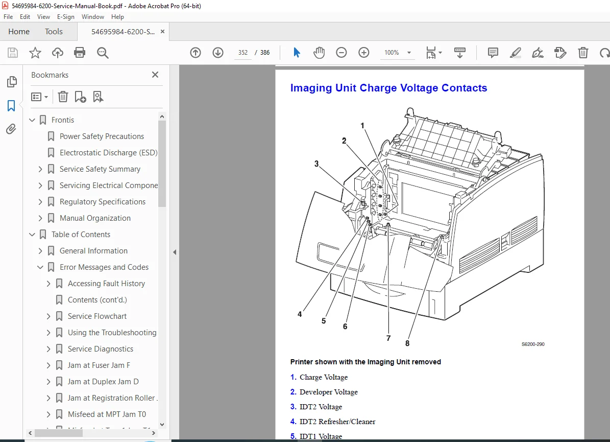
- Exploded View Diagrams
- Overall printer assembly
- Paper path assemblies
- Imaging system components
- Drive mechanism exploded views
- Electronic assemblies
- Part Number Cross-Reference
- Ordering information
- Replacement part identification
- Compatible components
CHAPTER 8 – THEORY OF OPERATION (Pages 361-375)
- Major Assembly Operation
- Laser scanning system
- Imaging process
- Toner transfer mechanism
- Fusing process
- Paper transport system
- Switches and Sensors
- Sensor locations and functions
- Switch operation
- Interlock mechanisms
- Safety switches
- Drives and Gears
- Main drive system
- Paper path drives
- Imaging drum drive
- Fuser drive mechanism
- Paper Path Detailed Description
- Paper pickup sequence
- Registration process
- Transfer process
- Exit path operation
- Duplex operation (if equipped)
CHAPTER 9 – PLUG/JACK LOCATOR MAPS (Pages 376-380)
- Wiring Harness Connector Maps
- Main board connectors
- Power supply connections
- Control panel harness
- Sensor connectors
- Motor connections
- Switch connectors
- Connector Pinout Diagrams
- Pin assignments
- Signal descriptions
- Voltage specifications
CHAPTER 10 – WIRING DIAGRAM (Pages 381-386)
- Master Wiring Diagram
- Complete electrical schematic
- Power distribution
- Signal routing
- Ground connections
- Interface connections
KEY FEATURES OF THIS SERVICE MANUAL:
✓ Official Xerox factory service documentation ✓ Complete troubleshooting procedures with flowcharts ✓ Comprehensive error code reference with solutions ✓ Step-by-step FRU disassembly/replacement procedures with photos ✓ Service diagnostics tests and functions ✓ Complete parts list with exploded views and part numbers ✓ Color registration and calibration procedures ✓ NVRAM reset and configuration procedures ✓ Theory of operation for major assemblies ✓ Wiring diagrams and connector pinouts ✓ Cleaning and maintenance schedules ✓ ESD precautions and safety procedures ✓ Professional Xerox service standards
Applications:
This Xerox Phaser 6200 service manual is essential for:
- Authorized Xerox service centers
- Independent printer repair shops
- IT support departments
- Corporate printer maintenance teams
- Technical training schools
- Field service engineers
Ideal For:
- Professional printer repair technicians
- Xerox certified service engineers
- IT support specialists
- Office equipment technicians
- Technical students and apprentices
- Print shop maintenance personnel
- Corporate IT departments
This comprehensive factory service manual provides the complete technical knowledge required to properly diagnose, repair, and maintain the Xerox Phaser 6200 Color Laser Printer, ensuring optimal performance and print quality.
FILE DETAILS:
| Specification | Details |
|---|---|
| Manual Title | Phaser 6200 Color Laser Printer Service Manual |
| Model Covered | Xerox Phaser 6200 Color Laser Printer |
| Publication Number | 071-0784-00 |
| Manufacturer | Xerox Corporation |
| First Printing | March 2002 |
| Total Pages | 386 pages |
| File Size | 11.8 MB |
| PDF Quality | 386 |
| Language | English |
| File Format | PDF (Optimized for printing and viewing) |
| Authors | Marni Peppin (MP), RJ |
| Created With | FrameMaker 6.0 / Acrobat Distiller 4.05 |