Xerox WorkCentre 6400 Service Manual 2009 – PDF DOWNLOAD
Original price was: $85.00.$20.95Current price is: $20.95.
Comprehensive Xerox WorkCentre 6400 multifunction printer service manual PDF from 2009, detailing error messages, troubleshooting, parts disassembly, and wiring diagrams. Includes WorkCentre 6400 error codes troubleshooting, Xerox 6400 print quality issues resolution, WorkCentre 6400 parts disassembly guides, and Xerox multifunction printer repair procedures for technicians maintaining legacy systems.
Description
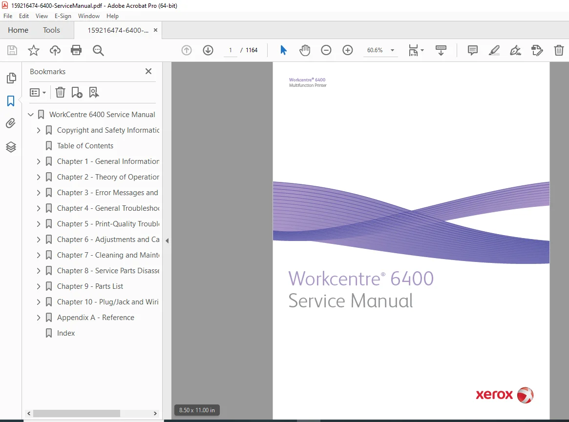
Xerox WorkCentre 6400 Service Manual 2009 – PDF DOWNLOAD
Description
This official Xerox WorkCentre 6400 service manual PDF (701P48634, First Printing: May 2009) is a detailed guide for qualified service personnel, providing instructions on troubleshooting, repairs, and maintenance of the WorkCentre 6400 multifunction printer. It covers WorkCentre 6400 error codes troubleshooting, theory of operation, general troubleshooting steps, Xerox 6400 print quality issues analysis with test patterns, adjustments and calibrations, cleaning procedures, WorkCentre 6400 parts disassembly sequences, parts lists with PL references, and WorkCentre 6400 wiring diagrams for electrical diagnostics. Essential for Xerox multifunction printer repair procedures, the manual includes safety warnings and emphasizes avoiding unauthorized servicing to prevent injury.
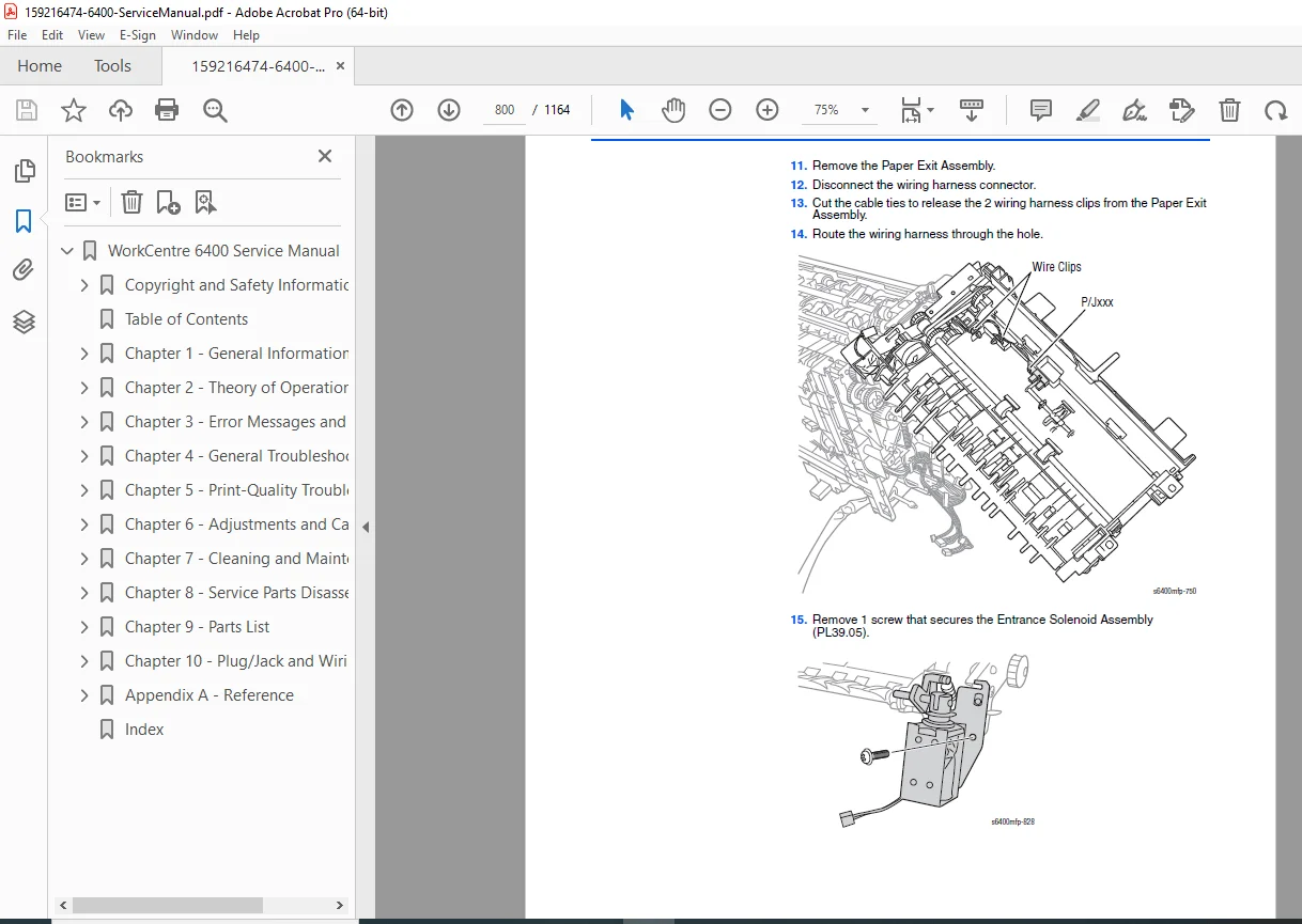
With illustrations and diagrams, it addresses components like DADF, scanner, fuser, toner cartridges, transfer belts, optional feeders, and finishers, ensuring effective resolution of jams, faults, and image defects through Xerox 6400 print quality issues troubleshooting and WorkCentre 6400 parts disassembly methods.
Table of Contents (neatly categorized for easy navigation):
- 1 General Information (Page 1-2 to 1-44)
- Printer Introduction and Overview
- Technical Support Information
- Printer Configurations
- Parts of the Printer (Front and Side Views, Rear View, Internal Components, Finisher, Scanner, Hard Disk Drives, Duplex Unit)
- Control Panel Configurations
- Printer Options (Fax, Printer Stand, Optional 500-Sheet Feeder Unit (Tray 3 and Tray 4), Finisher, Foreign Device Interface)
- Maintenance and Consumable Items
- Specifications (Printer Specifications, Scanning Specifications, Copy Specifications, Fax Specifications, Memory Specifications, Environment Specifications, Electrical Specifications, Print Speed, Warm-Up Time, First Print Output Time, First Copy Output Time, Image Specifications)
- Physical Dimensions and Clearances (Printer Dimensions, Mounting Surface Specifications, Paper and Tray Specifications)
- Toner Cartridge Life
- Maintenance Function (Firmware Update, Diagnostics)
- Controller Functions (Capture, Print, Save, and Reprint, Contention Management, Interrupt Printing, Job Priority Setup, Secure Print, Workflow Scanning)
- Information Pages and Reports (Information Pages, Reports, Support Pages)
- 2 Theory of Operation (Page 2-2 to 2-147)
- Table of Contents
- WorkCentre 6400 Operational Overview (System Overview)
- Major Assemblies and Functions
- Image Creation, Transfer, and Fixing
- Paper Path of the Printer (Paper Path Route)
- Image Input Terminal (Duplex Automatic Document Feeder, Scanner Assembly)
- Image Output Terminal (Electrical Components, Laser Unit, Toner Cartridge and Level Detection, Waste Toner Collection, Imaging Unit, Developer, Ozone Ventilation Mechanism, Transfer Belt (1st Image Transfer), Transfer Roller (2nd Image Transfer Roller), Paper Feed (Tray 1), Paper Feed (Tray 2), IDC Sensor (Density Control), Registration Roller, Fusing, Horizontal Transport, Image Quality Control (Image Stabilization), Fan Assemblies)
- Duplex Unit (Duplex Reverse Mechanism, Paper Transport and Duplex Paper Feed, Duplex 2-Sided Printing Method)
- Optional 500-Sheet Feeder (Drive Mechanism, Paper Feed Control)
- Finisher (Paper Path, Paper Transport, Top Tray Transport, Main Tray Transport, Storage, Main Tray, Stapling Unit)
- 3 Error Messages and Codes (Page 3-2 to 3-174)
- Introduction (System Status Embedded Page, Status Messages and Faults)
- Servicing Instructions
- Messages, Chain Link Codes, and Procedures (Fault Codes Summary, Status Message Summary)
- Fault Codes (Detailed procedures for various faults like doors open, blinking LEDs, system faults, jams, scanner faults, misfeeds, xerographic errors, auto calibration failed, fuser errors, finisher errors, etc.)
- Status Messages (Toner cartridge issues, trays full/empty/open, fuser missing, imaging unit reseat, non-Xerox supplies, etc.)
- 4 General Troubleshooting (Page 4-2 to 4-74)
- System Startup
- Power On Self Test (POST) (Sequence, POST LEDs)
- Service Diagnostics (Entering Service Diagnostics, Using Service Diagnostics)
- Service Diagnostics Menu Map
- Printer Components (Engine Motors and Clutches, ADF Motors and Clutches, ADF Sensors, Engine Sensors and Switches, Sensors (Paper Path))
- Duplex Unit Components (Duplex Unit Sensors and Motors)
- Optional 500-Sheet Feeder Components (Optional 500-Sheet Feeder Sensors, Switches, Clutch, Motor, and Board)
- Finisher Components (Finisher Sensors, Solenoids, Motors, and Switch; Finisher Sensors, Solenoids, Motors, and Board; Finisher Tray Sensors and Motor; Finisher Paper Path Sensors)
- Service Diagnostics Tests (Service Diagnostic Routines, dc104 – Usage Counters, dc108 – Software Version, dc120 – Fault Counters, dc122 – Fault History, dc135 – CRU/HFSI, dc140 – Analog Monitor, dc312 – Network Echo Test, dc330 – Component Control, dc575 – Scanner Test, dc612 – Print Test Pattern, dc640 – Video Path Integrity)
- Adjustments
- Maintenance (dc103 – Billing Plan, dc120 – Fault Counters, dc122 – Fault History, dc135 – CRU/HFSI Status and Reset, dc137 – PagePack)
- Call Closeout (Service Mode Exit)
- General Troubleshooting (Entering Machine Status/ Tools Menu, Resetting UI to Factory Settings, Software Reset, Service Copy Mode, Cloning)
- Control Panel Troubleshooting (Control Panel LED’s Do Not Light, Control Panel LED’s are On, Control Panel Display is Blank)
- Inoperable Printer Troubleshooting (Printer Continually Displays “The Fuser is Warming Up”, System Does Not Respond, Power Cycle the Printer)
- AC Power Supply Troubleshooting
- DC Power Supply Troubleshooting (LVPS)
- Image Processor Board Troubleshooting
- DADF Troubleshooting (Frequent Paper Jam, Frequent Double Feed and Skew)
- Scanner Troubleshooting (Scanner Fault Troubleshooting)
- Fax Troubleshooting (Initial Fax Checks, Fax Troubleshooting Tools, Fax Troubleshooting Procedures, Troubleshooting Sending or Receiving a Fax)
- Operating System and Application Problems (Verify Settings, Windows 2000, Windows XP, Windows Server Troubleshooting, Verify Driver Installation, Macintosh Troubleshooting (Mac OS 10.3 and Higher), UNIX/ Linux)
- 5 Print-Quality Troubleshooting (Page 5-2 to 5-79)
- Print-Quality Problems Overview (Defects Associated with Printer, DADF, and Scanner Components)
- Checklist Before Troubleshooting Print-Quality (Checking the Printer Condition, Checklist)
- Print-Quality Troubleshooting Pages and Test Patterns (Accessing Troubleshooting Print-Quality Pages, Print Test Patterns (dc612), Cyan 50% Fill, Magenta 50% Fill, Yellow 50% Fill, Black 50% Fill, Manufacturing Test Page 1/ Registration Print, Manufacturing Test 2/ Delta-E Print, Manufacturing Test 3/ Ghosting Print, Print-Quality Troubleshooting Pages)
- Print-Quality Specifications (Environmental Condition, Quality Paper, Paper Storage and Condition, Printer Condition)
- Troubleshooting Procedures (Print-Quality and Copy/ Scan Defect Definitions, Repeating Defect Measurement)
- Print-Quality Troubleshooting (Vertical Bands, Voids, or Streaks in All Colors, Horizontal Bands, Voids, or Streaks, Uneven Density in the Feed Direction, Uneven Density in the Scan Direction, Light Prints, Gradation Reproduction Failure, Background Contamination, Poor Color Reproduction, Void Areas or White Spots, Random Spots, Blurred Image, Blank Print, Black Print, Color Registration, Incomplete Fusing or Cold Offset, Residual Image, Ghosting, or Hot Offset, Smudges or Smears, Smears or Streaks on Back Side of Page, Uneven Pitch, Defects in One Color (C, M, Y, or K), Skew, Damaged Paper)
- Copy/Scan Troubleshooting (Lines, Spots, Streaks & Smears, Background Color, Text, and Images on Copies are Too Light, Too Dark, or Blurry, Skew, Damaged Paper, Wavy Lines, Spots Present in Copies, Image Does Not Appear, Large Jitter, Image Mis-registered, Image Unclear)
- 6 Adjustments and Calibrations (Page 6-2 to 6-23)
- Overview (Accessing the Service Diagnostics, Accessing the Machine Status/Tools Menu)
- Adjustments (Tray Adjustment (Tray 3/4 Margins), dc130 – Image Position (Margin Adjustment), dc131 – NVM Read/Write, dc301 – NVM Initialization, dc361 – NVM Save and Restore, dc608 – Document Feeder Registration, dc609 – Document Glass Registration, dc909 – Calibrate for Paper Type, dc936 – Image Quality Calibration, dc960 – Altitude Adjustment)
- Calibrations (Color Calibration, Altitude Adjustment, Calibrate Paper Type, Document Feeder Registration, Document Glass Registration, Image Position (Margin Adjustment), Image Quality Calibration, Control Panel Diagnostics, Scanner Calibration)
- 7 Cleaning and Maintenance (Page 7-2 to 7-19)
- Service Maintenance Procedure (Recommended Tools)
- Cleaning (Cleaning the Control Panel, Inspecting and Cleaning the DADF Feed Rollers and Pads, Cleaning the Tray 1 Feed Roller, Cleaning the Tray 2/3/4 Feed Roller, Cleaning the Duplex Unit Feed Rollers, Cleaning the Tray 3/4 Transport Rollers, Cleaning the Laser Lens, Cleaning the IDC Sensor, Cleaning the Document Glass)
- Maintenance (RIP (Repair, Inspect, and Prevent) Procedure)
- 8 Service Parts Disassembly (Page 8-2 to 8-217)
- Table of Contents
- Overview (Standard Orientation of the Printer, Notations in the Disassembly Text, Preparation, Fastener Types)
- Maintenance Items and Consumables (Tray 1 Separation Roller Assembly, Tray 1 Feed Roller, Toner Cartridge (Y/M/C/K), Imaging Unit (Y/M/C/K), Ozone Filter, Waste Cartridge, Transfer Belt, Transfer Roller, Fuser Unit, Tray 2/3/4 Separation Roller Assembly, Tray 2 Feed Roller, Tray 3/4 Feed Roller)
- Duplex Automatic Document Feeder (DADF) (DADF Separator (Feed) Roller Assembly, DADF Paper Tray Assembly, DADF Top Cover Assembly, Duplex Automatic Document Feeder Assembly, DADF Separator Pad Assembly, Holder Assemblies, Pressure Spring)
- Scanner Assembly
- Covers (Control Panel, Rear Cover, Right Rear Cover, Right Front Cover, Front Door Assembly, Left Side Cover)
- Paper Trays (Tray 1, Tray 2 Paper Size Switch, Tray 2 Paper Size Switch Actuator, Tray 2 Paper Empty Sensor, Tray 2 Paper Empty Sensor Actuator, Tray 2)
- Paper Feed and Registration (Pressure/ Retraction Clutch-1, Vertical Transport Assembly (Right Door), Registration Clutch, Registration Roller Assembly, Upper Horizontal Transport Assembly, Lower Horizontal Transport Assembly, Fuser Pawl, Paper Exit Assembly, Tray 2 Separation Roller Clutch)
- Electrical (Control Panel PWB, Control Panel LCD Assembly, Ribbon Cables, Toner Low Sensor Board (TLSB) Assembly, Low Voltage Power Supply (LVPS), Temperature/ Humidity Sensor, Registration Sensor, OHP Sensor, Image Density Control Sensor Board (IDCSB) (Front and Rear), Hard Disk Drives, RF Protective Shield, Image Processor Board, MCU Board (Engine Control Board), High Voltage Power Supply-1, High Voltage Power Supply-2, Card Cage, Fax Board, NVM Module, RAM)
- Xerographics (CRUM Reader, Waste Toner Auger Assembly, Front Imaging Unit Holder, Rear Imaging Unit Holder, Laser Unit)
- Drive Assembly (Pressure/ Retraction Sensor 2, 2nd Image Transfer Pressure/ Retraction Drive Assembly, Paper Take-Up Drive Assembly, Main Drive Assembly, Hopper Drive Assembly)
- Fans and Motors (Ozone Ventilation Fan, DC Power Supply Fan, Fuser Fan, LVPS Cooling Fan, I/P Board Cooling Fan, Color Photo Conductor Drum Motor (IBT Motor), Developer Motor K, Intermediate Transport Motor, Fuser Motor, Toner Supply Motor (Y/M), Toner Supply Motor (C/K))
- Optional 500-Sheet Feeder (Optional 500-Sheet Feeder Board, Tray 3/4 Paper Size Switch Actuator, Tray 3/4 Paper Size Switch, Optional 500-Sheet Feeder, Tray 3/4 Paper Feed Sensor Actuator, Tray 3/4 Paper Feed Clutch-1, Transport Motor, Tray 3/4)
- Duplex (Duplex Unit Right Cover, Duplex Unit Reverse Motor, Duplex Unit, Duplex Unit Control Board, Duplex Unit Transport Motor)
- Finisher (Option) (Finisher Rear Cover, Finisher Front Cover, Finisher Assembly, Finisher Cover Assembly, Paper Level Sensor, Finisher Right Plate, Switch Assembly, Finisher Top Right Cover, Entrance Sensor, Neutralizing Brush Assembly, Finisher Top Tray, Paper Exit Assembly, Finisher Guide Assembly, Finisher Entrance Solenoid, Finisher Roll Assembly, Storage Section Sensor, Roller Assembly, Stapler Assembly, Alignment Belt Up/ Down Solenoid, Finisher Control Board, Finisher Transport Motor, Finisher Exit Motor, Finisher Motor Fan, Finisher Exit Roller Up/ Down Motor, Finisher Main Tray)
- Printer Stand (Option) (Stand Assembly)
- 9 Parts List (Page 9-2 to 9-99)
- Serial Number Format
- Using the Parts List
- Overview Parts (Parts List – Overview)
- Print Engine Parts (PL 1.0 Duplex Automatic Document Feeder Assembly, PL 2.0 Scanner Assembly, PL 3.0 Covers, PL 4.0 Main Frame, PL 5.0 Tray 1 (Manual Feed), PL 6.0 Imaging Unit Rail, PL 7.0 Imaging Unit Contact, PL 8.0 Waste Toner Transport (1 of 2), PL 9.0 Waste Toner Transport (2 of 2), PL 10.0 LVPS/ Laser Unit, PL 11.0 Drive (1 of 3) – 2nd Transfer Pressure/ Retraction, PL 12.0 Drive (2 of 3) – Main Drive, PL 13.0 Drive (3 of 3) – Toner Supply (Hopper), PL 14.0 Transfer Belt Unit, PL 15.0 Vertical Transport Unit (1 of 2), PL 16.0 Vertical Transport Unit (2 of 2), PL 17.0 Horizontal Transport Unit, PL 18.0 Fuser Unit, PL 19.0 Paper Exit, PL 20.0 Electrical Components, PL 21.0 500-Sheet Tray, PL 22.0 Duplex Unit (1 of 2), PL 23.0 Duplex Unit (2 of 2), PL 24.0 Wiring (1 of 2), PL 25.0 Wiring (2 of 2), PL 26.0 Wiring Accessories, PL 27.0 Accessories)
- Option – 500-Sheet Feeder (PL 28.0 Optional 500-Sheet Tray 3/4 (1 of 7), PL 29.0 Optional 500-Sheet Tray 3/4 (2 of 7) – Paper Take-up Section, PL 30.0 Optional 500-Sheet Tray 3/4 (3 of 7) – Drive Section, PL 31.0 Optional 500-Sheet Tray 3/4 (4 of 7) – Paper Feed Tray Section, PL 32.0 Optional 500-Sheet Tray 3/4 (5 of 7) – Paper Feed Tray Section, PL 33.0 Optional 500-Sheet Tray 3/4 (6 of 7) – Wiring Accessories, PL 34.0 Optional 500-Sheet Tray 3/4 (7 of 7) – Accessory Parts)
- Option – Finisher (PL 35.0 Cover (1 of 2), PL 36.0 Cover (2 of 2), PL 37.0 Frame, PL 38.0 Paper Entrance, PL 39.0 Paper Transport (1 of 2), PL 40.0 Paper Transport (2 of 2), PL 41.0 Alignment (1 of 2), PL 42.0 Alignment (2 of 2), PL 43.0 Storage (1 of 2), PL 44.0 Storage (2 of 2), PL 45.0 Stapler Unit, PL 46.0 Drive (1 of 2), PL 47.0 Drive (2 of 2), PL 48.0 Main Tray)
- Option – Printer Cart (PL 49.0 Printer Stand)
- Xerox Supplies and Accessories
- Service Kits/Tools
- 10 Plug/Jack and Wiring Diagrams (Page 10-2 to 10-62)
- Plug/Jack Diagrams and Designators (Main Body Plug/Jack Designators (including Duplexer), Optional 500-Sheet Feeder Plug/Jack Designators, Finisher Plug/Jack Designators)
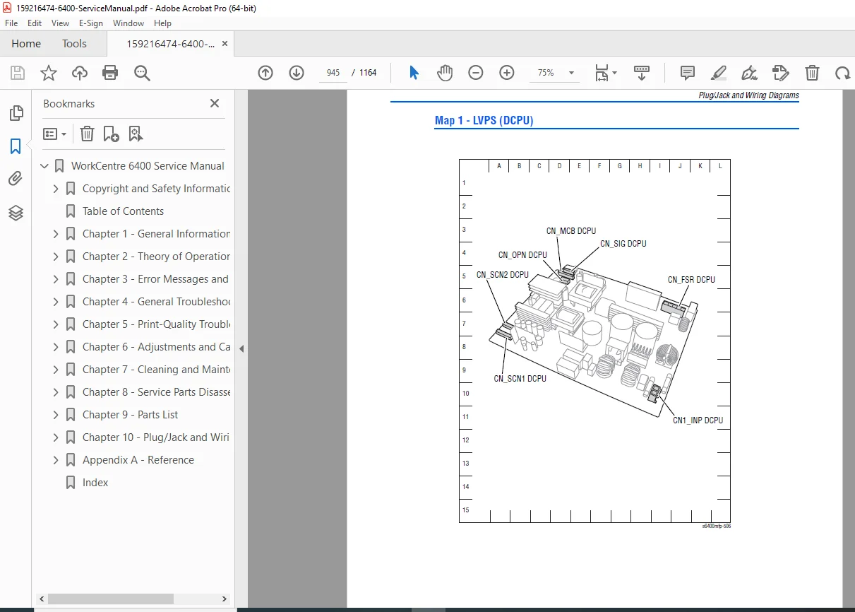
- Plug/Jack Locators (Map 1 – LVPS (DCPU), Map 2 – HVPS-1, Map 3 – HVPS-2, Map 4 – Image Processor Board, Map 5 – MCU Board (Engine Control Board), Map 6 – Duplex Unit Board (ADCB), Map 7 – Optional 500-Sheet Feeder Board (PCCB), Map 8 – Finisher Control Board (FSCB))
- Notations Used in the Wiring Diagrams
- Print Engine Wiring Diagrams (General Wiring Diagram Configurations, Print Engine Wiring Diagram Configurations, Various detailed diagrams for components, boards, sensors, motors, etc.)
- Options Wiring Diagrams (Optional 500-Sheet Feeder Wiring Diagram Configurations, Finisher Wiring Diagram Configurations, Optional 500-Sheet Feeder Board, Tray 3/4 Optional 500-Sheet Feeder Board, Finisher Control Board (FSCB), Finisher – Sensors, Stapler Cover Switch, Motors, Solenoids, Fan and Align Motors, Entrance Solenoid)
- A Reference (Page A-2 to A-160)
- Firmware Update (Send DLM File via the WebUI, USB Upgrade, USB ALTBOOT)
- Back Channel Traces
- Fault Codes
- Status Codes
- NVM Value (Fax NVM, Copy Controller NVM)
- WorkCentre 6400 Menu Map
- Internal Page Samples (Graphics Demo, Office Demo, Copy/Fax Activity Reports, Fax Protocol/Group Directory/Options/Pending Jobs, Color Fills, Manufacturing Tests, Repeating Defects)
- Fax Communication Commands Definitions
- Acronyms and Abbreviations
Index (Page I-1 to end): Alphabetical listing of terms, parts, procedures, and page numbers for quick reference, including entries like 2nd Image Transfer Pressure/Retraction Drive Assembly, acronyms (e.g., ADC, DADF, IOT), fault codes, NVM values, and more.
Note: The detailed table of contents and index facilitate navigation for WorkCentre 6400 error codes troubleshooting and Xerox multifunction printer repair procedures.
This vintage manual supports legacy Xerox 6400 finisher service instructions and comprehensive diagnostics.
File Details
- Manual Name: WorkCentre 6400 Service Manual
- Models Covered: WorkCentre 6400 Multifunction Printer
- Year: 2009
- Manual PDF Quality: High (clear text, diagrams, and illustrations from scanned original)
- No of Pages: 1164