Yale Forklift C818 (GC_GLC_GDC070-120MJ, GC_GLC_GDC080-120LJ_MJBCS) Service Manual PDF
$36.95
Yale Forklift C818 (GC_GLC_GDC070-120MJ, GC_GLC_GDC080-120LJ_MJBCS) Service Manual – PDF DOWNLOAD
Description
Yale Forklift C818 (GC_GLC_GDC070-120MJ, GC_GLC_GDC080-120LJ_MJBCS) Service Manual – PDF DOWNLOAD
FILE DETAILS:
Yale Forklift C818 (GC_GLC_GDC070-120MJ, GC_GLC_GDC080-120LJ_MJBCS) Service Manual – PDF DOWNLOAD
Language : English
Pages : 1208
Downloadable : Yes
File Type : PDF
IMAGES PREVIEW OF THE MANUAL:
TABLE OF CONTENTS:
Yale Forklift C818 (GC_GLC_GDC070-120MJ, GC_GLC_GDC080-120LJ_MJBCS) Service Manual – PDF DOWNLOAD
524150774-0600YRM0705-(03-2006)-US-EN 1
toc 1
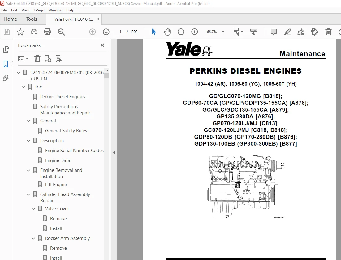
Perkins Diesel Engines 1
Safety Precautions Maintenance and Repair 2
General 9
General Safety Rules 9
Description 10
Engine Serial Number Codes 13
Engine Data 13
Engine Removal and Installation 15
Lift Engine 15
Cylinder Head Assembly Repair 15
Valve Cover 15
Remove 15
Install 16
Rocker Arm Assembly 16
Remove 16
Install 16
Disassemble 16
Inspect 17
Assemble 17
Valve Clearance Adjustments 17
Four-Cylinder Engines 18
Six-Cylinder Engines 18
Valve Springs 18
Cylinder Head Assembly 20
Remove 20
Install 22
Valves and Valve Springs 26
Remove 26
Inspect 26
Install 27
Valve Guides 27
Inspect 27
Remove 28
Install 28
Cylinder Head and Valve Seats 28
Inspect 28
Repair 28
New Valve Seats, Install 28
Piston and Connecting Rod Assemblies Repair 30
Rod Bearings 30
Remove 31
Install 31
Piston and Connecting Rod Assembly 32
Service Note 32
Remove 32
Install 33
Piston Rings 34
Remove 34
Inspect 34
Install 34
Piston and Connecting Rod 35
Disassemble 35
Inspect 36
How to Select Correct Replacements 36
Install 37
Piston Cooling Jets 37
Remove 37
Install 38
Crankshaft Assembly Repair 38
General 38
Crankshaft Pulley 39
Engine AR, Remove 39
Engines YG and YH, Remove 39
Inspect 40
Engine AR, Install 40
Engines YG and YH, Install 40
Rear Oil Seal 41
Replace 41
Main Bearings 42
Remove 42
Inspect 43
Install 43
Thrust Washers 43
Crankshaft Axial Movement, Check 43
Remove 44
Install 44
Crankshaft 45
Remove 45
Inspect 45
Install 45
Flywheel 47
Remove 47
Ring Gear, Replace 47
Install 47
Flywheel Housing 48
Remove 48
Install 48
Timing Case and Timing Gears Repair 49
General 49
Timing Case Cover 49
Remove 49
Install 50
Front Oil Seal 50
Remove 50
Install 50
Crankshaft Pulley Wear Sleeve 51
Install 51
Idler Gear and Hub 51
Remove 51
Install 52
Air Compressor Drive, Bendix 53
Disassemble 53
Assemble 54
Fuel Injection Pump Gear 54
Remove 55
Install 55
Camshaft Gear 56
Remove 56
Install 56
Crankshaft Gear 57
Remove 57
Install 57
Timing Case 57
Remove 57
Install 58
Camshaft and Tappets 59
Remove 59
Install 59
Cylinder Block Assembly Repair 60
Description 60
Cylinder Block 60
Disassemble 60
Inspect 61
Assemble 61
Cylinder Bore (Four-Cylinder Engines) 61
Cylinder Liner (Six-Cylinder Engines) 62
Inspect 62
Cylinder Liner Condition, Check 62
Remove 63
Service Liner, Install 63
Partially Finished Liner, Install 65
Engine Timing 65
Description 65
How to Set Number One Piston to TDC on Compression Stroke 67
How to Set Number One Piston to TDC on Compression Stroke (Alter 67
Valve Timing, Check 68
Fuel Injection Pump Timing, Check 69
Turbocharger – Engine YH Repair 70
General 70
Remove 70
Install 70
Impeller and Compressor Housing, Clean 71
Lubrication System Repair 72
General 72
Oil Filter, Replace 72
Filter Head 72
Remove and Install 72
Oil Sump 73
Remove 73
Install 73
Oil Pump 73
Remove 73
Inspect 74
Install 75
Relief Valve 75
Remove 75
Disassemble 76
Inspect 76
Assemble 76
Install 76
Idler Gear Shaft, Replace 77
Remove 77
Remove (Alternative) 77
Install 78
Install (Alternative) 78
Install (Alternative for Four-Cylinder Engines Only) 79
Fuel System Repair 79
Description 79
Fuel Injection Pump 80
Remove 80
Install 81
Check and Adjust 81
Fuel System Air Removal 82
Fuel Filter, Replace 83
Canister Type 83
Quick Release Canister Type 84
Fuel Injectors 85
Remove 85
Inspect 85
Install 85
Fuel Pump 86
Remove 86
Disassemble 86
Assemble 87
Install 88
Test 88
Cooling System Repair 88
General 88
Thermostat 88
Remove 88
Install 89
Test 89
Coolant Pump 89
Remove 89
Disassemble 90
Assemble 91
Install 94
Fan and Fan Drive 94
Remove 94
Install 95
Oil Cooler (Six-Cylinder Engines) 95
Remove 95
Disassemble and Assemble 95
Install 96
Oil Cooler Bypass Valve 96
Electrical Equipment Repair 96
Drive Belts 96
Adjustment 96
Remove 97
Install 97
Alternator 97
Remove 97
Install 97
Starter Motor 98
Remove 98
Install 98
Cold Start Aid 98
Air Compressor – Engines YG and YH 98
General 98
Repair 98
Remove 98
Install 99
Rotary Exhauster Replacement 100
Remove 100
Clean 100
Install 100
Engine Specifications 101
Cylinder Head Assembly 101
Piston and Connecting Rods 104
Crankshaft Assembly 107
Crankshaft Overhaul 108
Timing Case and Drive Assembly 110
Engine Block Assembly 111
Turbocharger 114
Lubrication System 114
Fuel System 115
Cooling System 117
Flywheel and Housing 117
Electrical Equipment 118
Torque Specifications 118
Cylinder Head Assembly 118
Piston and Connecting Rod Assemblies 118
Crankshaft Assembly 118
Timing Case and Drive Assembly 119
Turbocharger 119
Lubrication System 119
Fuel System 119
Cooling System 119
Flywheel 119
Auxiliary Equipment 119
Special Torque Specifications 120
Flywheel and Housing 120
Turbocharger 120
Electrical Equipment 120
Auxiliary Equipment 120
Special Tools* 121
Troubleshooting 126
tables 1
Table 1 Cylinder Head 101
Table 2 Valve Guides 101
Table 3 Inlet Valves 101
Table 4 Exhaust Valves 102
Table 5 Valve Springs 104
Table 6 Tappets 104
Table 7 Rocker Arm Shaft 104
Table 8 Rocker Arms and Bushings 104
Table 9 Pistons (Engine AR) 104
Table 10 Pistons (Engines YG and YH) 104
Table 11 Piston Rings (Engine AR) 105
Table 12 Piston Rings (Engines YG and YH) 105
Table 13 Piston Pins 106
Table 14 Connecting Rods 106
Table 15 Small End Bushings 106
Table 16 Connecting Rod Bearings (Engines AR and YG) 106
Table 17 Connecting Rod Bearings (Engine YH) 106
Table 18 Piston Cooling Jets 107
Table 19 Crankshaft 107
Table 20 Main Bearings 107
Table 21 Crankshaft Thrust Washers 107
Table 22 Crankshaft Heat Treatment 108
Table 23 Crankshaft Overhaul Specifications 108
Table 24 Maximum Variation (Run-out) 110
Table 25 Camshaft 110
Table 26 Camshaft Thrust Washer 110
Table 27 Camshaft Gear 110
Table 28 Gear for Fuel Injection Pump 111
Table 29 Crankshaft Gear 111
Table 30 Idler Gear and Hub 111
Table 31 Cylinder Block (Engine AR) 111
Table 32 Cylinder Bore Specifications 112
Table 33 Cylinder Block (Engines YG and YH) 113
Table 34 Cylinder Liners (Engines YG and YH) 113
Table 35 Cylinder Liner Specifications (Partially Finished) 113
Table 36 Oil Pump (Engine AR) 114
Table 37 Oil Pump (Engines YG and YH) 114
Table 38 Idler Gear for Oil Pump 114
Table 39 Relief Valve 115
Table 40 Oil Filter 115
Table 41 Lucas Fuel Injection Pump 115
Table 42 Fuel Injector Codes 116
Table 43 Fuel Pump (Engine AR) 117
Table 44 Fuel Pump (Engines YG and YH) 117
Table 45 Fuel Filter 117
Table 46 Coolant Pump 117
Table 47 Thermostat 117
Table 48 Fan Drive Housing 117
Table 49 Limits for Flywheel Run Out and Alignment (Total Indic 117
Table 50 Alternator 118
Table 51 Starter Motor 118
Table 52 Cold Start Aid 118
Table 53 List of Possible Causes 126
524150775-0700YRM0626-(03-2003)-US-EN 131
toc 131
Cooling System 131
Safety Precautions Maintenance and Repair 132
General 135
Description 136
Radiator 136
Radiator Cap 136
Thermostat 136
Water Pump 137
Fan and Fan Shroud 137
Cooling System Checks 137
Radiator 137
Thermostat 137
Water Pump 138
Exhaust Leaks 138
Fan and Fan Shroud 138
Radiator Cleaning 138
Drain 138
Clean 138
Fill 139
Troubleshooting 140
524150783-1600YRM0326-(03-2007)-US-EN 143
toc 143
Steering Axle 143
Safety Precautions Maintenance and Repair 144
General 147
Description 147
Steering Axle Assembly Repair 152
Steering Axle GP/GLP/GDP070-110LG/MG (B813), GC/GLC070-120LG/MG 152
Remove 152
Install 152
Steering Axle GDP60-70CA (GP/GLP/GDP135-155CA) (A878, B878), GLP 153
Remove 153
Install 153
Wheels and Hubs Repair (All Units) 154
Remove and Disassemble 154
Clean 154
Inspect 154
Assemble and Install 154
Spindles and Bearings Repair (All Units) 156
Remove 156
Clean 156
Assemble and Install 157
Tie Rods Repair (All Units) 158
Remove 158
Clean 158
Install 158
Steering Cylinder Repair 161
Remove and Disassemble 161
Clean and Inspect 161
Assemble and Install 161
Troubleshooting 162
524150791-2200YRM0002-(01-2016)-US-EN 167
General 171
Description 172
Alternator Repair 174
Alternator Type A 174
Remove and Disassemble 174
Clean 176
Assemble 176
Install 177
Alternator Type B 180
Remove and Disassemble 180
Clean 180
Assemble 181
Install 182
General Check and Adjustment 182
Low Output Check (Type A or Type B) 183
High Output Check (Type A or Type B) 186
Brushes Circuit Check 187
Delco Alternators 187
Motorola Alternators 187
Diodes Check 188
Diode Bridge Check 188
Delco and Leece-Neville Alternators 188
Motorola Alternators 188
Rotor Field Winding Check 189
Stator Windings Check 190
Voltage Regulator Check 190
Troubleshooting 190
524150797-8000YRM0231-(02-2023)-US-EN 195
General 201
Threaded Fasteners 201
Nomenclature, Threads 201
Strength Identification 202
Cotter (Split) Pins 203
Fastener Torque Tables 208
Conversion Table 210
524150797-8000YRM0231-(03-2020)-US-EN 217
General 221
Threaded Fasteners 221
Nomenclature, Threads 221
Strength Identification 222
Cotter (Split) Pins 223
Fastener Torque Tables 228
Conversion Table 230
524153896-0100YRM0981-(02-2007)-US-EN 237
toc 237
Frame 237
Safety Precautions Maintenance and Repair 238
Description 241
Counterweight Repair 242
Remove 242
Install 247
Exhaust System Repair 249
Muffler 249
Remove 249
Install 249
Exhaust Pipe – LPG/Gas Engine 250
Remove 250
Install 250
Exhaust Pipe – Diesel Engine 253
Remove 253
Install 253
Hood Repair 254
Remove 254
Install 254
Overhead Guard Repair 255
Remove 255
Install 255
LED Backup and Brake Lights, Replace 255
Remove 255
Install 255
Operator Restraint System Repair 256
Automatic Locking Retractor (ALR) 256
Emergency Locking Retractor (ELR) 257
Radiator and Coolant System 258
Remove 258
Install 258
Alternator Replacement 260
Remove 260
Install 260
Engine Removal and Installation 260
Remove 260
Install 262
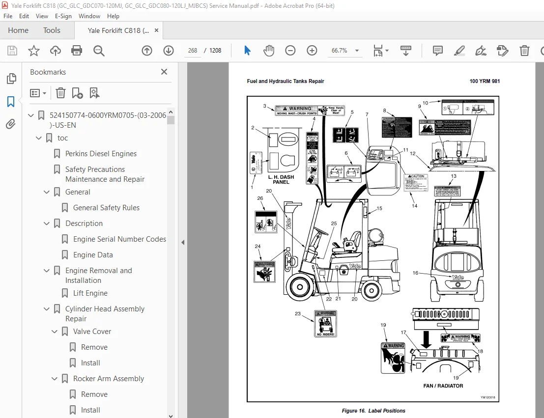
Fuel and Hydraulic Tanks Repair 266
Inspect 266
Repairs, Small Leaks 266
Repairs, Large Leaks 266
Clean 266
Steam Method of Cleaning 266
Chemical Solution Method of Cleaning 267
Other Methods of Preparation for Repair 267
Safety Labels 269
tables 237
Table 1 Weight of Counterweights 247
524153897-0600YRM0590-(04-2014)-US-EN 273
524153900-0900YRM0348-(03-2003)-US-EN 325
toc 325
LPG Fuel System 325
Safety Precautions Maintenance and Repair 326
General 329
Description and Operation 330
Fuel Tank 330
Fuel Filter and Fuel Valve Unit 331
Vaporizer 332
Carburetor 333
Governor 335
LPG Tank Repair 336
Remove 336
LPG Tanks With Fixed Mounting Bracket 336
LPG Tanks With EZ Lift Mounting Bracket 336
Install 337
LPG Tanks With Fixed Mounting Bracket 337
Hydrostatic Relief Valve Repair 338
Remove and Install 338
Filter Unit Repair 339
Fuel Filter Element, Replace 339
Diaphragm and Fuel Valve, Replace 339
Hoses Replacement 341
Vaporizer Repair 341
Remove 341
Disassemble 341
Clean 341
Inspect 341
Assemble 343
Install 346
Carburetor Repair 347
Remove 347
Disassemble 347
Clean 347
Assemble 347
Install 347
Governor Repair 348
Filter Unit Check 350
Vaporizer Check 350
Pressure Reducer Valve 350
Vapor Valve 350
Carburetor Adjustment 350
Idle Mixture 350
Idle Speed 350
Power Mixture 350
Throttle Linkage Adjustment 351
Adjustment For Models GDP60-70CA (GP/GLP/GDP135-155CA), GC/GLC07 351
Adjustment For Models GC070-120LJ/MJ 351
Troubleshooting 352
524153901-1300YRM0397-(02-2004)-US-EN 359
toc 359
Single-Speed Powershift Transmission 359
Safety Precautions Maintenance and Repair 360
General 363
Transmission Repair 363
Remove 363
Disassemble 364
Transmission, Disassemble 364
Input Shaft, Disassemble 365
Reverse Clutch, Disassemble 367
Output Shaft (Pinion) and Differential, Remove and Disassemble 370
Clean and Inspect 372
Assemble 372
Input Shaft, Assemble 373
Reverse Clutch, Assemble 381
Output Shaft (Pinion) and Differential, Assemble and Install 386
Transmission, Assemble 393
Control Valve, Install 396
Install 396
Control Valve Repair 397
Remove, Early Model GC/GLC070-120LG/MG Lift Trucks 397
Disassemble, Early Model GC/GLC070-120LG/MG Lift Trucks 397
Assemble, Early Model GC/GLC070-120LG/MG Lift Trucks 398
Install, Early Model GC/GLC070-120LG/MG Lift Trucks 398
Remove and Disassemble, Later Model GC/GLC070-120LG/MG Trucks an 398
Inspect, Later Model GC/GLC070-120LG/MG Trucks and GC070-120LJ/M 401
Assemble and Install, Later Model GC/GLC070-120LG/MG Trucks and 401
Foot Directional Control Pedal Repair 403
Remove and Disassemble, GC/GLC070-120LG/MG Model Lift Trucks 403
Assemble and Install, GC/GLC070-120LG/MG Model Lift Trucks 404
Remove and Disassemble, GC070-120LJ/MJ Model Lift Trucks 405
Assemble and Install, GC070-120LJ/MJ Model Lift Trucks 406
Direction Control Lever Repair 408
Remove and Disassemble 408
Assemble and Install 408
Stall Test 409
Linkages Adjustment 410
Linkage for Inching/Brake Pedal, GC/GLC070-120LG/MG (B818) Lift 410
Linkage for Direction Control Lever 412
Linkage for Inching/Brake Pedal, GC070-120LJ/MJ (C818, D818) Lif 412
Brake Shoe Adjustment 412
Inching/Brake Pedal Height Adjustment 412
Single Pedal Height Adjustment 412
Two Pedal Height Adjustment 412
Inching/Brake Linkage Adjustment 414
Oil Pressures Check 416
System Pressure Check Port 416
Torque Converter Check Port 416
Clutch Pressure Check Port 417
Inching Pressure 417
Solenoid Check Ports ( Foot Directional Control Only) 419
Lubrication Pressure Check Ports 419
System Pressure Check Port 419
Torque Converter Check Port 419
Reverse Clutch Pressure Check Port 419
Forward Clutch Pressure Check Port 419
Lubrication Pressure Check Port 419
Modulator Pressure Check Port 419
Troubleshooting 420
tables 359
Table 1 Ring and Pinion Tooth Contact Adjustment 391
Table 2 Stall Speed Specifications 409
Table 3 Transmission Oil Pressure Check, Early Model GC/GLC070- 417
Table 4 Transmission Oil Pressure Check, Later Model GC070-120L 418
524153902-1300YRM0399-(09-2003)-US-EN 427
toc 427
Single-Speed Powershift Transmission 427
Safety Precautions Maintenance and Repair 428
General 431
Mechanical Description 431
General 431
Torque Converter 431
Oil Pump 431
Shaft Assemblies 431
Input Shaft 431
Reverse Clutch Shaft 431
Countershaft 432
Ring Gear, Pinion, and Differential 432
Clutch Assemblies 433
Hydraulic Operation 434
Torque Converter 434
Shaft Assemblies 435
Control Valve 435
General 435
System Regulator 435
Clutch Pressure Regulator 435
Torque Converter Regulator 435
Inching Spool 435
Direction Spool, Manual Control 438
Direction Spool, Foot Directional Control Pedal 438
Modulation Spool 438
Accumulator 438
Drain Spool 438
Foot Directional Control Pedal 439
Control Valve 439
General 439
Regulator for Clutch Pressure 439
Inching Spool Assembly 439
Direction Spool 441
Direction Spool, Manual Control 441
Modulator Circuit 441
Regulator for Torque Convertor 441
Lubrication Circuit 441
Direction Control Lever 442
Foot Directional Control Pedal 443
Start Circuit, Foot Directional Control Pedal 444
Creep Speed Switch 444
Oil Flow Diagrams 445
Neutral 445
Forward 445
Forward-Inching 445
Reverse 445
524153903-1400YRM0984-(09-2003)-US-EN 461
toc 461
Drive Axle 461
Safety Precautions Maintenance and Repair 462
General 465
Description 465
Drive Axle Repairs 465
Remove and Disassemble 465
Clean and Inspect 467
Brakes 467
Drive Axle 468
Assembly and Installation 468
Torque Specifications 470
Troubleshooting 471
524153904-1600YRM0732-(10-2003)-US-EN 475
toc 475
Steering Control Unit 475
Safety Precautions Maintenance and Repair 476
General 479
Description 479
Operation 479
Steering Wheel and Column Assembly Repair 481
Remove and Disassemble 481
Assemble and Install 481
Steering Control Unit 484
Disassemble 484
Clean 486
Assemble 487
System Air Removal 490
Troubleshooting 490
524153906-1800YRM0985-(05-2005)-US-EN 495
toc 495
Brake System 495
Safety Precautions Maintenance and Repair 496
General 499
Description and Operation 499
Brake Booster and Master Cylinder 499
Service Brake Assembly 499
Parking Brake 499
Brake Shoe Assemblies Repair 500
Remove and Disassemble 500
Clean 500
Inspect 503
Assemble and Install 503
Brake Booster and Master Cylinder 506
Remove 506
Disassemble 506
Clean and Inspect 506
Assemble 506
Install 506
Brake Booster Filter, Replace 506
Parking Brake Repair 508
Remove and Disassemble 508
Assemble and Install 508
Brake System Air Removal 510
Brake Pedal Adjustment 510
Parking Brake Adjustment 510
Parking Brake Not Applied Switch Test 511
Parking Brake Switch Test ( Foot Directional Control Pedal Only) 511
Brake Shoes Adjustment 512
Troubleshooting 512
524153907-1900YRM0097-(05-2012)-US-EN 517
toc 517
Hydraulic Gear Pumps 517
Safety Precautions Maintenance and Repair 518
Description 521
Operation 522
Flow Control Valve 522
Relief Valve 522
Hydraulic Gear Pump Repair 523
Remove 523
Disassemble 524
Clean 524
Inspect 525
Assemble 528
Install 530
Pump Output Check 530
Method No 1 530
Method No 2 531
Hydraulic System Air Check 532
Troubleshooting 533
524153908-1900YRM0339-(10-2003)-US-EN 539
toc 539
Hydraulic Pump Drive Assembly 539
Safety Precautions Maintenance and Repair 540
General 543
Description 543
Hydraulic Pump Drive Assembly Repair 544
Remove and Disassemble 544
Clean 545
Inspect 545
Assemble and Install 545
Troubleshooting 546
524153909-1900YRM0743-(06-2005)-US-EN 549
toc 549
Hydraulic System 549
Safety Precautions Maintenance and Repair 550
General 553
Description 553
Operation 555
Hydraulic Pump GLP/GDP 3 5-5 5LJ/MJ (GP/GLP/GDP70-120LJ/MJ) 555
Hydraulic Pump GC070-120LJ/MJ 555
Main Control Valve 555
Steering Control Unit 556
Specifications 556
Hydraulic System Capacity (Powershift) 556
Hydraulic System Capacity (Hydrostatic) 556
Hydraulic Tank Capacity (Powershift and Hydrostatic) 557
Hydraulic Tank Capacity 557
Relief Pressures @ 2200 RPM, 50 to 80 C ( 120 to 180 F) 557
Hydraulic Pump Flow to Valve 557
Steering Priority Flow 557
Troubleshooting 557
Lift, Lower and Tilt Circuit 558
Steering Circuit 559
524153910-2000YRM0754-(12-2003)-US-EN 563
toc 563
Main Control Valve 563
Safety Precautions Maintenance and Repair 564
General 567
Description 567
Operation 567
Lift Section 567
Tilt and Auxiliary Sections 571
Reattaching the Clevis End of the Tilt Spool 572
Relief Valve 572
Main Control Valve Repair 572
Remove and Disassemble 572
Clean and Inspect 574
Assemble 576
Install 576
Pressure Relief Valve Check and Adjustment 577
Main Relief Valve (Lift) 577
Steering Relief Valve 577
Secondary Relief Valve (Tilt and Auxiliary) 580
Specifications 581
Troubleshooting 581
524153911-2100YRM0986-(11-2004)-US-EN 587
toc 587
Tilt Cylinders 587
Safety Precautions Maintenance and Repair 588
General 591
Description 591
Tilt Cylinder Repair 591
Remove 591
Disassemble 591
Clean 591
Inspect 591
Assemble 592
Install 593
Tilt Cylinder Leak Check 594
Tilt Cylinder Stroke and Mast Tilt Angle Adjustment 594
Tilt Cylinder Specifications 594
tables 587
Table 1 Leak Check Specifications 594
524153913-2200YRM0755-(10-2003)-US-EN 597
toc 597
Starter 597
Safety Precautions Maintenance and Repair 598
General 601
Description 601
Yoke Assembly 602
Armature Assembly 602
Clutch Assembly 602
Magnetic Switch Assembly 602
Operation 602
Starter Repair 603
Remove 603
Disassemble 604
Clean 607
Assemble 608
Install 611
General Checks and Adjustments 611
Armature Tests 612
Armature Short Circuit Test 612
Armature Winding Ground Test 612
Commutator Run-Out Test 612
Yoke Test 613
Brush and Brush Holder Check 613
Brush Holder Insulation Test 613
Clutch Test 613
Magnetic Switch Test 614
Pull-In Test 614
Hold-In Test 614
Return Test 614
Performance Tests 615
No-Load Test 615
Troubleshooting 615
524153914-2200YRM0107-(03-2008)-US-EN 621
toc 621
High Energy Ignition (HEI) System 621
Safety Precautions Maintenance and Repair 622
Description 625
Distributor Repair 627
Remove 627
Disassemble 627
Assemble 633
Install, If Crankshaft WAS NOT Rotated when Distributor was Remo 634
Install, If Crankshaft WAS Rotated when Distributor was Removed 634
Ignition Coil Replacement 636
Some Four- and Six-Cylinder Models 636
Remove 636
Install 636
V8, Some Four- and Six-Cylinder Models 637
Remove 637
Install 637
Electronic Module Replacement 638
Remove 638
Install 638
Sensing Coil Replacement 640
Remove 640
Install 640
Spark Plugs Replacement 640
Remove 640
Install 641
Visual Check 641
High Voltage Wires Check 641
Ignition Coil Check 642
Coil in Distributor Cap Design 642
Separate Coil Design 642
Sensing Coil, Check 643
Electronic Module Check 643
Ignition Timing Adjustment 644
GM V8-366 (6-liter) Ignition System Check 645
GM V6-LPG (4 3 liter) GM V6-LPG (4 3 liter) Ignition Timing and 645
Specifications 645
Troubleshooting 646
524153915-2200YRM0756-(02-2007)-US-EN 651
toc 651
Instrument Panel Indicators and Senders 651
Safety Precautions Maintenance and Repair 652
General 655
Description 655
Instruments and Senders 655
Password Function 661
Supervisor Password Function 661
Entering Operator Passwords 661
Deleting Operator Passwords 662
Retrieve the Most Recent Operator Password Used to Enable the Tr 662
Display All Operator Passwords Programmed Into the System 662
Enable and Disable Operator Passwords Function 662
Allow Supervisor Password to Enable the Truck to Start 662
Operator Passwords Function 662
Component Replacement – General Information 663
Sender Replacement 663
Fuel Level Sender 663
Pressure and Temperature Sender 664
Seat Sensor, Operator Presence System (OPS) 665
Remove 665
Install 665
Operator Presence System Module Replacement 665
Remove 665
Install 667
Display Panel Replacement 668
Specifications 670
Troubleshooting 671
Troubleshooting For Operator Presence System GP/GLP/GDP70-120LJ/ 672
Troubleshooting For Operator Presence System GC70-120LJ/MJ (C818 674
tables 651
Table 1 Instrument Panel Description 656
Table 2 Sender Description 660
Table 3 Meter and Sender Specifications 670
Table 4 Troubleshooting Procedure for the Operator Presence Mod 672
Table 5 Troubleshooting Procedure for the Operator Presence Mod 674
524153916-2200YRM0765-(03-2003)-US-EN 679
toc 679
Microprocessor Spark Timing System (MSTS) 679
Safety Precautions Maintenance and Repair 680
General 683
Description 684
What MSTS Does 684
How MSTS Begins Operation 684
Operation 685
Distributor 685
Ignition Coil 686
Ignition Module 686
When Engine Is Being Started 686
When Engine Is Running 688
Manifold Absolute Pressure (MAP) Sensor 689
Engine Coolant Temperature (ECT) Sensor 689
MSTS Module Corrections 690
Troubleshooting 691
General 691
Tools and Test Equipment 693
MSTS 694
Troubleshooting Procedure 694
Where to Start 694
Visual/Physical Inspection 694
Knowledge/Tools Required 694
Damage From Static Discharge (Static Electricity) 695
Troubleshooting Information 695
Malfunction Indicator Lamp (MIL) 695
Connecting CodeMate Tester 695
Reading Diagnostic Trouble Codes (DTC) 696
Clearing Diagnostic Trouble Codes (DTC’s) 697
On-Board Diagnostic (OBD) System Check 697
Test Description 697
No Malfunction Indicator Lamp 699
Circuit Description 699
Test Description 699
No DTC-12, Malfunction Indicator Lamp ON 701
Circuit Description 701
Test Description 701
Starter Rotates Engine, Engine Does Not Run 702
Test Description 702
DTC-14 Engine Coolant Temperature (ECT) (Low Temperature Indicat 706
Circuit Description 706
Test Description 706
DTC-15 Engine Coolant Temperature Sensor (ECT) (High Temperature 708
Circuit Description 708
Test Description 708
DTC-34 Manifold Absolute Pressure (MAP) Sensor 710
Circuit Description 710
Test Description 710
DTC-41 Electronic Spark Timing (EST) Open Circuit 713
Circuit Description 713
Test Description 713
DTC-42 Electronic Spark Timing (EST) Grounded Circuit 715
Circuit Description 715
Test Description 715
DTC-51 MSTS Failure 717
Circuit Description 717
Distributor Repair 717
Remove 717
Disassemble 718
Inspect 718
Assemble 718
Install 719
Ignition Timing 719
Ignition Module Repair 720
Test For Fault 720
Replace 720
Sensing Coil Repair 721
Test For Fault 721
Replace 721
Ignition Coil Repair 722
Test For Fault 722
Remove 722
Install 722
MSTS Module Repair 723
Remove 723
Install 723
ECT Sensor Replacement 723
MAP Sensor Replacement 724
tables 679
Table 1 MSTS Module Connections 692
Table 2 Pressure Conversion Chart 693
Table 3 MSTS Diagnostic Codes 695
524153917-2200YRM0781-(03-2003)-US-EN 727
toc 727
Electronic Engine Control 727
Safety Precautions Maintenance and Repair 728
General 731
Description and Operation 731
General 731
Electronic Control Module (ECM) 731
Diagnostic Connector 731
How ECM Begins Operation 735
Electronic Engine Control 736
What ECM Does 736
Distributor 738
Ignition Module 738
When Engine Is Being Started 739
When Engine Is Running 740
Electronic Control Module (ECM) with Ignition Module Distributor 740
Fuel Control 741
Throttle Body Injection (TBI) 742
Fuel Injectors 742
Fuel Pressure Regulator 742
Throttle Position Sensor (TPS) 743
Idle Air Control (IAC) 743
GM 4 3L Engine Governor System 744
GM 3 0L Engine Governor System 744
Vacuum Ports 746
Fuel Pump 746
ECM Sensors and Controllers 748
Manifold Absolute Pressure (MAP) 748
Engine Coolant Temperature (ECT) Sensor 748
524153918-2200YRM0782-(03-2003)-US-EN 751
toc 751
Electronic Engine Control 751
Safety Precautions Maintenance and Repair 752
General 757
Troubleshooting Procedure 757
How This Section Is Arranged 757
Where Do I Start? 757
Visual/Physical Inspection 757
Knowledge/Tools Required 757
Damage From Static Discharge (Static Electricity) 757
Troubleshooting Information 758
Malfunction Indicator Lamp (MIL) 758
Reading Diagnostic Trouble Codes (DTC) 758
Clearing Diagnostic Trouble Codes (DTCs) 762
ECM Diagnostic Codes Available 763
Diagnostic Mode 763
Field Service Mode 763
ECM Learning Ability 763
SCAN Tool Information 764
On-Board Diagnostic (OBD) System Check 765
Test Description 765
Troubleshooting Charts 767
General 767
Tools and Test Equipment 767
Troubleshooting Chart Description Summary 768
A-1 – No Malfunction Indicator Lamp 768
Circuit Description 768
Test Description 769
Other Troubleshooting Checks 769
A-2 – No Scan Data, No DTC 12, Malfunction Indicator Lamp ON 771
Circuit Description 771
Test Description 771
A-3 – Starter Rotates Engine, Engine Will Not Run 773
Circuit Description 773
Test Description 773
Other Troubleshooting Checks 773
A-4 – Fuel Injector Circuit 775
Test Description 775
A-5 – Fuel Pump Relay Circuit 777
Circuit Description 777
Test Description 777
Other Troubleshooting Checks 777
A-6 – Fuel System Troubleshooting 779
Circuit Description 779
Test Description 779
Other Troubleshooting Checks 779
Test Description 781
Fuel Pressure Check 783
A-7 – Ignition System Troubleshooting 783
Test Description 784
DTC 14 Engine Coolant Temperature Sensor Circuit (Low Temperatur 787
Circuit Description 787
Test Description 787
Other Troubleshooting Checks 787
DTC 15 Engine Coolant Temperature Sensor Circuit (High Temperatu 789
Circuit Description 789
Test Description 789
Other Troubleshooting Checks 789
DTC 21 Throttle Position Sensor Circuit (Signal Voltage High) 791
Circuit Description 791
Test Description 791
Other Troubleshooting Checks 791
DTC 22 Throttle Position Sensor Circuit (Signal Voltage Low) 793
Circuit Description 793
Test Description 793
Other Troubleshooting Checks 793
DTC 31 Engine Governor Circuit 795
Circuit Description 795
Test Description 795
Other Troubleshooting Checks 795
DTC 33 Manifold Absolute Pressure (MAP) Sensor Circuit (Signal V 797
Circuit Description 797
Test Description 797
Other Troubleshooting Checks 797
DTC 34 Manifold Absolute Pressure (MAP) Sensor Circuit (Signal V 799
Circuit Description 799
Test Description 799
Other Troubleshooting Checks 799
DTC 41 Electronic Spark Timing (EST) – Open EST Circuit 801
Circuit Description 801
Test Description 801
Other Troubleshooting Checks 801
DTC 42 EST – Grounded EST Circuit, Open or Grounded Bypass Circu 803
Circuit Description 803
Test Description 804
Other Troubleshooting Checks 804
DTC 51 ECM Failure 806
Circuit Description 806
Other Troubleshooting Checks 806
Troubleshooting, Poor Operation 807
General 807
Make a Careful Visual Check 807
FAULT: Codes or Performance That Is Not Regular 807
FAULT: Loss of Diagnostic Trouble Code (DTC) Memory 807
FAULT: Engine Quits While Driving 807
Additional Checks 807
FAULT: Engine Is Difficult to Start 807
FAULT: Variation in Engine Power When Throttle Is Held Steady 808
FAULT: Decreased Engine Power 808
FAULT: Detonation 809
FAULT: Engine Momentarily Does Not Increase Power When Throttle 809
FAULT: One or More Cylinders Do Not Operate Correctly – Engine D 810
FAULT: Rough Idle or Engine Stalls During Idle 810
FAULT: Fuel Usage Too High 810
FAULT: Dieseling 811
FAULT: Backfire 811
System Test Charts 811
General 811
Engine Coolant Temperature (ECT) Sensor Test 811
Throttle Position (TP) Sensor Check 812
Minimum Idle Speed 812
Adjustment 813
B-1 – Idle Air Control (IAC) System Check 814
Circuit Description 814
Other Troubleshooting Checks 814
B-2 – Manifold Absolute Pressure (MAP) Sensor Output Test 816
Circuit Description 816
Test Description 816
B-3 – Check Governor System 818
Governor System Not Operating Correctly 818
Check Function of Governor System 818
Check PCV System 819
Fuel System Components Repair 819
General 819
Fuel Pressure Relief Procedure 819
Fuel Pump Replacement 819
Throttle Body Injection Unit (TBI) 820
Remove 820
Clean and Inspect 821
Install 821
Fuel Meter Body 821
Remove 821
Install 824
Fuel Injector 824
Remove 824
Install 825
Pressure Regulator 825
Remove 825
Inspect 825
Install 825
Throttle Position Sensor (TPS) 826
Remove 826
Install 826
Idle Air Control (IAC) Valve 826
Remove 826
Clean and Inspect 826
Install 827
Governor System 3 0L Engine Repair 827
Governor Module, Replace 827
Governor Motor, Replace 827
Throttle Cables, Install and Adjust 827
Foot Directional Control Pedal, Check 828
Governor System 4 3L Engine Repair 829
Governor Throttle Drive Assembly 829
Remove 829
Inspect 830
Install 830
Governor Drive Motor 830
Remove 830
Clean and Lubricate 830
Install 831
Inspect 832
Ignition System Components Repair 832
ECM Replacement 832
Function Check 832
Distributor 832
Remove 832
Disassemble 832
Inspect 833
Assemble 833
Install 833
Firing Order 834
Ignition Timing 834
Ignition Module Repair 834
Test For Fault 834
Replace 835
Sensing Coil 835
Test 835
Replace 836
Ignition Coil 836
Test 836
Remove 836
Install 837
Sensors Repair 837
Engine Coolant Temperature (ECT) Sensor, Replace 837
MAP Sensor, Replace 837
PCV System Repair 838
Replace 838
Wiring 838
Connectors and Terminals 838
Procedures for Spark Plugs, Spark Plug Wires, and Boots 841
Wiring Diagram 841
Spark Plugs Troubleshooting 846
Special Tools 847
tables 751
Table 1 ECM Diagnostic Codes Available 763
Table 2 SCAN Tool Information 764
Table 3 Troubleshooting Chart Description Summary 768
Table 4 ECT Sensor – Temperature vs Resistance 789
Table 5 ECT Sensor – Temperature vs Resistance 812
Table 6 ECM Connector J1 Identification 844
Table 7 ECM Connector J2 Identification 845
524153919-4000YRM0741-(03-2005)-US-EN 851
toc 851
Lift Cylinders 851
Safety Precautions Maintenance and Repair 852
Safety Procedures When Working Near Mast 855
General 857
Description 857
Lowering Control Valve (Velocity Fuse) 857
Lift Cylinder Repair 860
Remove 860
Disassemble 861
Assemble 861
Install 861
Lift System Leak Check 862
Troubleshooting 863
524153920-4000YRM0736-(07-2010)-US-EN 867
toc 867
Masts 867
Safety Precautions Maintenance and Repair 868
General 871
Description and Operation 871
Carriages 871
Two-Stage Mast With Limited Free-Lift 871
Two-Stage Mast With Full Free-Lift 872
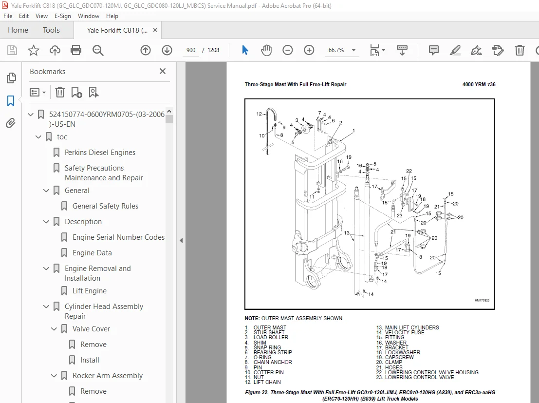
Three-Stage Mast With Full Free-Lift 873
Safety Procedures When Working Near Mast 875
Fork Replacement 877
Remove 878
Install 878
Carriage Repair 879
Remove 879
Sideshift Carriage Repair 881
Remove 881
Disassemble 881
Assemble 881
Install 881
Two-Stage Mast With Limited Free-Lift Repair 883
Remove, GLP/GDP3 5-5 5LJ/MJ (GP/GLP/GDP070-120LJ/MJ) Model Lift 883
Remove, GC070-120LJ/MJ, ERC070-120HG (A839), and ERC35-55HG (ERC 885
Disassemble 888
Clean and Inspect 888
Assemble 889
Install, GLP/GDP3 5-5 5LJ/MJ (GP/GLP/GDP070-120LJ/MJ) Lift Truck 890
Install, GC070-120LJ/MJ, ERC070-120HG (A839), and ERC35-55HG (ER 892
Two-Stage Mast With Full Free-Lift Repair 894
Remove 894
Disassemble 894
Clean and Inspect 896
Assemble 896
Install 896
Three-Stage Mast With Full Free-Lift Repair 898
Remove 898
Disassemble 898
Clean and Inspect 902
Assemble 902
Install 903
Mast Operation Check 909
Lift and Tilt System Leak Check 910
Lift System 910
Tilt System 911
Tilt Cylinder Stroke and Backward Tilt Angle Adjustment 912
Lift Chain Adjustments 914
Mast Adjustments 916
Carriage Adjustment 918
Troubleshooting 919
tables 867
Table 1 Tilt Cylinder Leak Check Specifications, GC070-120LJ/MJ 911
Table 2 Hook-Type Carriage Chain Adjustment 914
Table 3 Pin-Type Carriage Chain Adjustment 915
524153922-8000YRM0987-(06-2009)-US-EN 925
toc 925
Periodic Maintenance 925
Safety Precautions Maintenance and Repair 926
General 931
Serial Number Data 931
How to Move Disabled Lift Truck 931
How to Tow Lift Truck 931
How to Put Lift Truck on Blocks 932
How to Raise Drive Tires 932
How to Raise Steering Tires 932
Maintenance Schedule 933
Maintenance Procedures Every 8 Hours or Daily 940
How to Make Checks With Engine Stopped 940
Engine Oil 940
Hydraulic System Oil 940
Cooling System Reservoir Level 941
Fuel System 942
Battery 942
Tires and Wheels 943
Forks 943
Adjust 943
Hook Fork, Remove 943
Hook Fork, Install 945
Forks, Mast, and Lift Chains, Inspect 945
Operator Restraint System 946
Automatic Locking Retractor (ALR) 946
Emergency Locking Retractor (ELR) 946
Safety Labels 947
Cooling System, Clean Debris from Radiator Core 947
How to Make Checks With Engine Running 948
Gauges, Lights, Horn, and Fuses 948
Engine Oil Pressure 949
Cooling System Temperature 949
Powershift Transmission Oil level Check 949
Control Levers and Pedals 950
Lift System Operation 950
Service Brakes 950
Parking Brakes 951
Steering System 951
Maintenance Procedures Every 250 Hours or 6 Weeks 952
Engine Oil and Filter, GM V-6 Engines 952
Sideshift Carriage Lubrication 952
Tilt Cylinder Lubrication 953
Air Filter, GM V-6 EPA Compliant Engine 954
Maintenance Procedures Every 500 Hours or 3 Months 954
Lift Chain Lubrication 954
Engine Oil and Filter, Perkins Diesel Engine 954
Drive Belts 955
Fan Drive Belts 955
Perkins Diesel Engine 955
Alternator Drive Belt 955
GM 4 3L Engine 956
Serpentine Drive Belt 956
Tension Screw Adjustment 956
Hydraulic Tank Breather, Clean and Check 957
Brake Fluid 957
Lift Chains Wear Check 958
Forks, Wear and Damage Check 958
Mast Lubrication 958
Control Levers and Pedals Lubrication 959
Steering Axle Lubrication 959
Fuel System, Checks and Adjustments 959
LPG Carburetor 959
Fuel Injection (Perkins Engine) 959
GM V-6 Engine 959
Inching/Brake Pedal 959
Steering Tie Rods 959
Fork Pins and Guides 959
Wheel Nuts 960
Air Filter 960
Battery 960
Maintenance Procedures Every 1000 Hours or 6 Months 961
Fuel Filter, Replace (Diesel Engine) 961
Fuel System, Remove Air (Perkins 1004 42 Diesel Engine) 961
Water Separator, Diesel Engine 963
PCV Valve, GM V-6 963
Crankcase Breather, GM V-6 963
Valve Clearance, Check and Adjust 963
Differential and Drive Axle Oil 963
Spark Plugs, GM V-6 963
Ignition Timing 963
Cooling System, GM V-6 EPA Compliant Engine 964
LPG Fuel Filter GM V-6 EPA Compliant Engine, Replace 964
Inspect Engine Electrical System, Connectors, and FCVS Connectio 965
Maintenance Procedures Every 2000 Hours or Annually 965
Differential Thrust Screw 965
Hydraulic System 966
Hydraulic Oil and Filter, Replace 966
Powershift Transmission Oil and Filter, Replace 966
Spark Plugs, GM V-6 967
Cooling System 967
Wheel Bearings 967
Steering Wheels, Lubrication 967
Drive Wheels, Lubrication 967
PCV Valve, GM V-6 967
LPG Filter, Replace 967
Gasoline Fuel Filter, Replace 968
Brake Booster Filter, Replace 968
Differential Oil for Powershift Transmission, Replace 968
Air Filter Element, GM V-6 EPA Compliant Engine 968
Oxygen Sensor GM V-6 EPA Compliant Engine 968
Test LPG /GAS Regulator Pressure 968
Inspect Low Pressure Regulator (LPR) for Oil Buildup and Leaks 969
Check Throttle Shaft for Sticking 970
Inspect Exhaust Manifold and Piping for Leaks 970
Safety Procedures When Working Near Mast 970
Lift Chain Adjustments 972
Fuel Injectors Repair 973
Lift and Tilt System Leak Check 974
Lift Cylinders, Leak Check 974
Tilt System 974
Welding Repairs 975
Overhead Guard Changes 976
Wheel and Tire Replacement 977
Solid Rubber Tire, Change 977
Wheels, Install 977
tables 925
Table 1 Maintenance Schedule 934
Table 2 Hook-Type Carriage Chain Adjustment 972
Table 3 Pin-Type Carriage Chain Adjustment 973
Table 4 Tilt Cylinder Leak Check Specifications 975
524153923-8000YRM0988-(06-2005)-US-EN 981
toc 981
Capacities and Specifications 981
Safety Precautions Maintenance and Repair 982
Tire Sizes 985
Hydraulic System 985
Electrical System 985
Engine Specifications 986
Capacities 986
Lift Truck Weights 987
Transmission Pressures (Single-Speed Powershift) 988
Mast Speeds 989
Torque Specifications 989
Frame 989
Engine – GM V-6 989
Engine – Perkins 990
Transmission 990
Drive Axle 990
Steering System 990
Brake System 990
Hydraulic System 990
Main Control Valve 990
Tilt Cylinders 991
Lift Cylinders 991
Mast 991
524153924-8000YRM0989-(03-2007)-US-EN 995
toc 995
Diagrams 995
Safety Precautions Maintenance and Repair 996
General 999
524162462-2200YRM1016-(10-2004)-US-EN 1069
toc 1069
Electronic Engine Control 1069
Safety Precautions Maintenance and Repair 1070
General 1073
Description and Operation 1073
General 1073
Electronic Control Module (ECM) 1073
Diagnostic Connector 1073
How ECM Begins Operation 1077
Electronic Engine Control 1078
What ECM Does 1078
Distributor 1079
Ignition Module 1080
When Engine Is Being Started 1081
When Engine Is Running 1082
Electronic Control Module (ECM) with Ignition Module Distributor 1083
Fuel Control 1083
Throttle Body Injection (TBI) 1084
Fuel Injectors 1084
Fuel Pressure Regulator 1084
Throttle Position Sensor (TPS) 1085
Idle Air Control (IAC) 1085
GM 4 3L Engine Governor System 1086
GM 3 0L Engine Governor System 1086
Vacuum Ports 1088
Fuel Pump 1088
ECM Sensors and Controllers 1090
Manifold Absolute Pressure (MAP) 1090
Engine Coolant Temperature (ECT) Sensor 1090
524162463-2200YRM1017-(10-2004)-US-EN 1093
toc 1093
Electronic Engine Control 1093
Safety Precautions Maintenance and Repair 1094
General 1101
Troubleshooting Procedure 1101
How This Section Is Arranged 1101
Where Do I Start? 1101
Visual/Physical Inspection 1101
Knowledge/Tools Required 1101
Damage From Static Discharge (Static Electricity) 1101
Troubleshooting Information 1102
Malfunction Indicator Lamp (MIL) 1102
Reading Diagnostic Trouble Codes (DTC) 1102
Clearing Diagnostic Trouble Codes (DTCs) 1106
ECM Diagnostic Codes Available 1107
Diagnostic Mode 1107
Field Service Mode 1107
ECM Learning Ability 1107
SCAN Tool Information 1108
On-Board Diagnostic (OBD) System Check 1110
Test Description 1110
Troubleshooting Charts 1111
General 1111
Tools and Test Equipment 1112
Presssure Conversion Chart 1113
Troubleshooting Chart Description Summary 1114
A-1 No Malfunction Indicator Lamp 1115
Circuit Description 1115
Diagnostic Aids 1115
Test Description 1115
A-2 No Scan Data, No DTC-12, Malfunction Indicator Lamp ON 1117
Circuit Description 1117
Diagnostic Aids 1117
Test Description 1117
A-3 Engine Cranks but Does Not Run 1119
Circuit Description 1119
Diagnostic Aids 1119
Test Description 1119
A-4 Fuel Injector Circuit 1122
Circuit Description 1122
Test Description 1122
A-5 Fuel Pump Relay Circuit 1124
Circuit Description 1124
Diagnostic Aids 1125
Test Description 1125
A-6 Fuel System Troubleshooting 1127
Circuit Description 1127
Diagnostic Aids 1128
Test Description 1128
Test Description 1130
A-7 Ignition System Troubleshooting 1132
Circuit Description 1132
Diagnostic Aids 1132
Test Description 1132
DTC 14 ECT Sensor Circuit – Low Temp Indicated (Scan Diagnostics 1137
Circuit Description 1137
Diagnostic Aids 1137
Test Description 1138
DTC 15 Engine Coolant Temperature (ECT) Sensor Circuit High Temp 1139
Circuit Description 1139
Diagnostic Aids 1139
Test Description 1139
DTC 21 Throttle Position (TP) Sensor Circuit Signal Voltage High 1141
Circuit Description 1141
Diagnostic Aids 1141
Test Description 1141
DTC 22 Throttle Position (TP) Sensor Circuit Signal Voltage Low 1143
Circuit Description 1143
Diagnostic Aids 1143
Test Description 1143
DTC 31 Engine Governor Circuit 1145
Circuit Description 1145
Diagnostic Aids 1145
Test Description 1145
DTC 33 Manifold Absolute Pressure (MAP) Sensor Circuit Signal Vo 1147
Circuit Description 1147
Diagnostic Aids 1148
Test Description 1148
DTC 34 Manifold Absolute Pressure (MAP) Sensor Circuit Signal Vo 1150
Circuit Description 1150
Diagnostic Aids 1150
Test Description 1150
DTC 41 Electronic Spark Timing (EST) – Open EST Circuit 1152
Circuit Description 1152
Diagnostic Aids 1153
Test Description 1153
DTC 42 EST – Grounded EST Circuit, Open or Grounded Bypass Circu 1154
Circuit Description 1154
Diagnostic Aids 1154
Test Description 1154
DTC 51 Calibration Checksum Failure 1156
Circuit Description 1156
Diagnostic Aids 1156
Test Description 1156
DTC 81 Fuel Pump Relay Driver Circuit High, Low, or Open 1157
Circuit Description 1157
Diagnostic Aids 1158
Test Description 1158
DTC 81 5-Volt Reference Circuit Out of Range 1160
Circuit Description 1160
Diagnostic Aids 1160
Test Description 1160
DTC 81 FPRSENSE Circuit Fault 1162
Circuit Description 1162
Diagnostic Aids 1162
Test Description 1162
Troubleshooting, Poor Operation 1163
General 1163
Make a Careful Visual Check 1163
FAULT: Codes or Performance That Is Abnormal 1164
FAULT: Loss of Diagnostic Trouble Code (DTC) Memory 1164
FAULT: Engine Quits While Driving 1164
Additional Checks 1164
FAULT: Engine Is Difficult to Start 1164
FAULT: Variation in Engine Power When Throttle Is Held Steady 1165
FAULT: Decreased Engine Power 1165
FAULT: Detonation/Spark Knock 1165
FAULT: Engine Momentarily Does Not Increase Power When Throttle 1166
FAULT: One or More Cylinders Do Not Operate Correctly – Engine D 1166
FAULT: Rough Idle or Engine Stalls During Idle 1167
FAULT: Fuel Usage Too High 1167
FAULT: Dieseling 1167
FAULT: Backfire 1168
System Test Charts 1168
General 1168
Engine Coolant Temperature (ECT) Sensor Test 1168
Throttle Position (TP) Sensor Check 1169
Minimum Idle Speed 1169
Adjustment 1169
B-1 – Idle Air Control (IAC) System Check 1170
Circuit Description 1170
Diagnostic Aids 1171
B-2 – Manifold Absolute Pressure (MAP) Sensor Output Test 1172
Circuit Description 1172
Test Description 1172
B-3 – Check Governor System 1174
Governor System Not Operating Correctly 1174
Check Function of Governor System 1174
Check PCV System 1175
Fuel System Components Repair 1175
General 1175
Fuel Pressure Relief Procedure 1175
Fuel Pump Replacement 1175
Throttle Body Injection Unit (TBI) 1176
Remove 1176
Clean and Inspect 1176
Install 1177
Fuel Meter Body 1177
Remove 1177
Install 1180
Fuel Injector 1180
Remove 1180
Install 1181
Pressure Regulator 1181
Remove 1181
Inspect 1181
Install 1181
Throttle Position Sensor (TPS) 1182
Remove 1182
Install 1182
Idle Air Control (IAC) Valve 1182
Remove 1182
Clean and Inspect 1183
Install 1183
Governor System 3 0L Engine Repair 1183
Governor Module, Replace 1183
Governor Motor, Replace 1183
Throttle Cables, Install and Adjust 1183
Foot Directional Control Pedal, Check 1184
Governor System 4 3L Engine Repair 1185
Governor Throttle Drive Assembly 1185
Remove 1185
Inspect 1186
Install 1186
Governor Drive Motor 1186
Remove 1186
Clean and Lubricate 1187
Install 1187
Inspect 1187
Foot Directional Control Pedal, Check 1188
Ignition System Components Repair 1189
ECM Replacement 1189
Function Check 1189
Distributor 1189
Remove 1189
Disassemble 1189
Inspect 1190
Assemble 1190
Install 1190
Firing Order 1191
Ignition Timing 1191
Ignition Module Repair 1191
Test For Fault 1191
Replace 1192
Sensing Coil 1192
Test 1192
Replace 1193
Ignition Coil 1193
Test 1193
Remove 1193
Install 1194
Sensors Repair 1194
Engine Coolant Temperature (ECT) Sensor, Replace 1194
MAP Sensor, Replace 1194
PCV System Repair 1195
Replace 1195
Wiring 1195
Connectors and Terminals 1195
Procedures for Spark Plugs, Spark Plug Wires, and Boots 1198
Wiring Diagram 1198
Spark Plugs Troubleshooting 1202
Special Tools 1204
tables 1093
Table 1 ECM Diagnostic Codes Available 1107
Table 2 Rinda SCAN Tool Information 1108
Table 3 TECH 1 SCAN Tool Information 1108
Table 4 On-Board Diagnostic System Checks 1111
Table 5 Voltage and Pressure Chart 1113
Table 6 Troubleshooting Chart Description Summary 1114
Table 7 No Malfunction Indicator Lamp (GM 3 0L Engine Only) 1116
Table 8 No Scan Data, No DTC-12, Malfunction Indicator Lamp ON 1118
Table 9 Engine Cranks but Does Not Run 1120
Table 10 Fuel Injector Circuit 1122
Table 11 Fuel Pump Relay Circuit 1125
Table 12 A-6A Fuel System Troubleshooting 1128
Table 13 A-6B Fuel system Troubleshooting 1130
Table 14 Ignition System Troubleshooting 1133
Table 15 Engine Coolant Temperature Sensor 1137
Table 16 DTC 14 Engine Coolant Temperature (ECT) Sensor Circuit 1138
Table 17 Engine Coolant Temperature Sensor Table 1140
Table 18 DTC 15 Engine Coolant Temperature (ECT) Sensor Circuit 1140
Table 19 DTC 21 Throttle Position (TP) Sensor Circuit Signal Vo 1142
Table 20 DTC 22 Throttle Position (TP) Sensor Circuit Signal Vo 1144
Table 21 DTC 31 Engine Governor Circuit 1146
Table 22 DTC 33 Manifold Absolute Pressure (MAP) Sensor Circuit 1148
Table 23 DTC 34 Manifold Absolute Pressure (MAP) Sensor Circuit 1151
Table 24 DTC 41 Electronic Spark Timing (EST) – Open EST Circui 1153
Table 25 DTC 42 Electronic Spark Timing (EST) – Grounded EST Ci 1155
Table 26 DTC 51 Calibration Checksum Failure 1157
Table 27 DTC 81 Fuel Pump Relay Driver Circuit High, Low, or Op 1158
Table 28 DTC 81 5 Volt Reference Circuit Out of Range 1161
Table 29 DTC 81 FPRSENSE Circuit Fault 1163
Table 30 ECT Sensor – Temperature vs Resistance 1168
Table 31 Idle Air Control (IAC) System Check 1171
Table 32 Altitude Voltage Chart 1173
Table 33 Manifold Absolute Pressure (MAP) Sensor Output Test 1173
Table 34 Weather-Pack Terminal Repair 1198
Table 35 ECM Connector J1 Identification 1200
Table 36 ECM Connector J2 Identification 1201
S.V 06/24