Yale Forklift ERC 040-060 RA/ZA Service Maintenance Manual – PDF DOWNLOAD
$28.95
Yale Forklift ERC 040-060 RA/ZA Service Maintenance Manual – PDF DOWNLOAD
Description
Yale Forklift ERC 040-060 RA/ZA Service Maintenance Manual – PDF DOWNLOAD
FILE DETAILS:
Yale Forklift ERC 040-060 RA/ZA Service Maintenance Manual – PDF DOWNLOAD
Language : English
Pages : 315
Downloadable : Yes
File Type : PDF
IMAGES PREVIEW OF THE MANUAL:
TABLE OF CONTENTS:
Yale Forklift ERC 040-060 RA/ZA Service Maintenance Manual – PDF DOWNLOAD
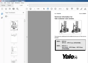
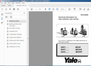
SUPPORT INFORMATION 1-1
SERVICE PARTS ORDERING INSTRUCTIONS 1-1
How То Order Service Parts 1-1
When Ordering Parts 1-1
SPECIAL TOOLS 1-1
TECHNICAL SERVICE PUBLICATIONS
OPERATOR TRAINING
DAILY OPERATOR CHECK-OFF LISTS
SERVICE TRAINING COURSES
SERVICE TRAINING MATERIALS
Section 2
GENERAL LIFТ TRUCK МAINTENANCE
AND LUBRICATION SCHEDULE
HOW ТО РUТ А LIFТ TRUCK ON BLOCKS
How То Raise The Drive Тires
How То Raise The Steering Тires
MAINТENANCE SCHEDULE
GENERAL LUBRICATION INSTRUCTIONS
EVERY 8 HOURS OR DAILY
HOW ТО МАКЕ CHECKS WITH ТНЕ
КЕУ swrrcн OFF
Hydraulic System
Battery
Forks · · · · · · · ·
Forks, Adjustment
Forks, Removal
Forks, lnstallation
lnspection Of Forks, Mast, And Uft Chains
Тires And Wheels
Operator Restraint System
Battery Restraint System
Safety LaЬels
HOW ТО МАКЕ CHECKS WITH ТНЕ
КЕУ SWITCH “ON ”
Gauges, Hom and Fuses
Pedals And Control Levers
Uft System Operation
Service Brakes
Parking Brake
Steering System
EVERY 350 HOURS OR ТWО MONTHS
Hydraulic Tank Breather
Diff erential And Speed Reducer
Wheel Nut Torques •
Steering Axle Spindles
Mast
Uft Chains
Forks
Вrake Ruid
Other Lubrication ,
Seat Brake
Electrical lnspection
Contactors
Motor Brushes
EVERY 2000 HOURS OR YEARL У
Wheel Bearings
Change the Hydraulic Oil and Rlter
Change Тhе Oil ln Тhе Differential
And Speed Reducer
Service Вrakes
Service Вrakes, Cleaning
Uft Chains
Contactors
GENERAL PROCEDURES
HOW ТО CHARGE ТНЕ ВАТТЕRУ
HOW ТО CHANGE ТНЕ ВАТТЕАУ
СНЕСК FOR LEAKS IN ТНЕ LIFТ
AND TILT SYSTEM
Check the Uft Cylinders for Leaks
Check the Тilt Cylinders for Leaks
LIFТ CHAIN ADJUSТMENТS
HOW ТО СНЕСК ТНЕ РМТ CIRCUIT
WELDING REPAIRS
FRAME
OVERHEAD GUARD
Changes То The Overhead Guard
Removal
lnstallation
HYDRAULIC TANK
lnspection
COUNТERWEIGHT
Removal
lnstallation
TIRES AND WHEELS
Solid Тires (Press-on)
lnstall Тhе Wheels
LABEL REPLACEMENT 2-28
HOW ТО PUT AN ELECTRIC SIT DOWN RIDER
TRUCK IN STORAGE 2-30
HOW ТО PUT BAТТERIES IN STORAGE 2-30
HOW ТО MOVE А DISABLED LIFТ TRUCK 2-31
How То Tow Тhе Uft Truck 2-31
SPECIFICATIONS 2-31
TORQUE SPECIFICATIONS 2-32
GENERAL GUIDE ТО TORQUE
VALUES (LBF-FТ) 2-33
GENERAL GUIDE ТО TORQUE VALUES 2-34
Sectlon З
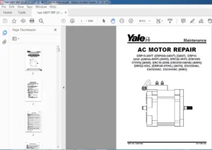
ELECTRIC MOTOR MAINТENANCE,
GENERAL 3-1
TRACTION MOTOR AND
HYDRAULIC PUMP MOTOR 3-1
DisassemЫy 3-1
AssemЫy 3-1
BRUSH AND COMMUТATOR INSPECTION 3-3
Normal Commutator Surface 3-4
Commutator ProЫems 3-5
BRUSH REPLACEMENТ, TRACTION
AND HYDRAULIC MOTORS 3-8
TESTS FOR А DAMAGED FIELD
AND ARMATURE 3-11
Test For An Open Circuit ln Тhе Armature 3-11
Test For А Short-Circuit ln An
Armature Winding З-11
Test For An Short-Circuit ln Тhе Armature 3-11
Test For Ап Ореп Circuit ln А Field Coil 3-11
Test For А Short-Circuit ln А Field Coil 3-12
Test For А Short-Circuit Between Тhе Field
And Тhе Motor Case 3-12
Brush Holder Test 3-12
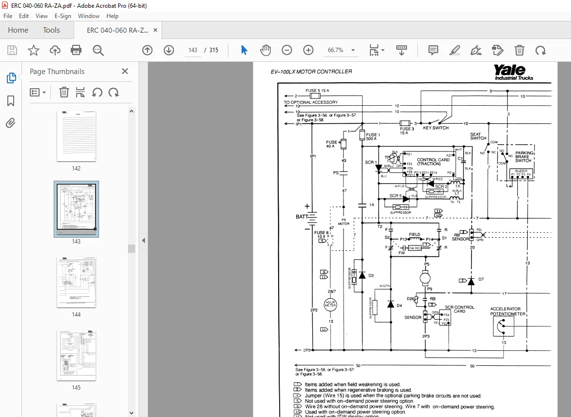
EV-100LX MOTOR CONТROLLER, GENERAL 3-13
ELECTRONIC SPEED CONТROLS 3-13
Тhе Silicon Controlled Rectifier (SCR) 3-14
А Motor Circuit That Operates With Pulses 3-15
Traction Circuit 3-16
Hydraulic Pump Motor 3-16
Тhе SCR 1 “OFP’ Circuit 3-16
INDUCTION CURRENТ FROM ТНЕ MOTOR 3-18
ТНЕ CONТROL CARD 3-19
Pulse Monitor Trip (РМТ)
(Тraction Circuit Only) 3-20
SRO Circuit (Тraction Circuit Only) 3-20
Control Card Adjustments (Тraction Circuit) 3-20
Accelerator Control 3-24
ra,e
lndustrisl Trucks
SCR CONТROL (HYDRAULIC PUMP MOTOR) 3-24
CONТACTORS 3-24
CIRCUIT PROTECTION 3-25
Traction Circuit Fuse 3-25
Current Umit 3-25
ТhermaJ Protection 3-25
Suppressors 3-25
SEQUENCE OF OPERATION 3-25
CONТROLCARD,CHECKS
AND ADJUSTMENТS 3-26
Status Codes _
HAND SET
INSTRUMENТ PANEL DISPLAY
Battery Gauge With Lift lnterrupt
(Curtis 933/1 or Curtis 933/4
Lift lnterrupt Controller) 3-28
Вattery Gauge With Uft lnterrupt And
Вrush Wear lndicator (General Electric) 3-29
lnstrument Panel Display (I T W Controller) 3-30
Мotor Temperature lndicators
Вrush Wear lndicators
CONТROL CARD CONNECTIONS
CHECKS AND ADJUSТMENТS,
CONТROL CARD
Function Codes
Checks And Adjustments On Тhе Bench
When Тhе Hand Set Is Connected То А
Control Card lnstalled ln А Uft Truck
FUNCTION SEТТINGS, CHECKS
AND ADJUSTMENТS
Genera! •
How То Connect, Disconnect,
And Check Тhе Hand Set
How То Check And Adjust Functions
FUNCTION DESCRIPTIONS
Traction Control Cards
(laЬel letters – ТХ and ТТ)
Pump Control Card (label letter РХ)
ТаЫеs for the Function Value Settings
TROUBLESHOOTING
REPAIRS
FUSES
CHECKING AN SCR
Тhе SCR 1 AssemЫy
Тhermal Protector 3-79
Replacing Тhе SCR 1 AssemЫy 3-79
ТНЕ “OFP’ CIRCUIT FOR SCR 1 3-80
Check The Reactor AssemЫy 3-80
Check Suppressors For SCR 2 And SCR 5 3-80
Yale lndustna/ Trucks
Check SCR 2 And SCR 5 3-80
REPACING ТНЕ SCR 2 AND SCR 5 3-81
Check Capacitor С1 3-81
DIODES D3 ANO 04 3-81
Check Тhе Oiodes 03 And 04 3-81
Replacement, Oiodes 03 and 04 3-81
MOTOR CURRENТ SENSOR 3-81
CONТACTORS 3-81
Contactor Repair 3-82
CONТROL CARO 3-83
CONТROL CARO PLUGS 3-83
CONТROL SWITCHES 3-84
Seat Switch 3-84
Кеу Switch 3-84
Direction Control Switch {Steering Column) 3-84
Parking Brake Switch And Buzzer Alarm 3-85
Start Switch 3-85
Accelerator Circuit ‘ 3-85
SCHEMATIC ANO WIRING DIAGRAMS 3-89
Figure 3-55 Schematic Oiagram,
EV-100LX Мotor Controller 3-89
Figure 3-56 GE Battery lndicator With Brush
Wear lndicator Display, Uft lnterrupt, And With
SCR Control Of Тhе Hydraulic Pump 3-91
Figure 3-57 Curtiss[ 933/4 Or 933/1
Battery lndicator With Lift lnterrupt And
Without SCR Control Of The Hydraulic Pump 3-92
Figure 3-58 Wiring Oiagram, Curtiss[ 933/4
Or 933/1 Battery lndicator With Lift lnterrupt
And Without SCR Control Of Тhе
Hydraulic Pump 3-93
Figure 3-59 Wiring Diagram, EV-100LX Motor
Controller 3-95
Figure 3-60 Battery lndicator
Without Uft lnterrupt And Without
SCR Control Of Тhе Hydraulic Pump 3-97
Figure 3-61 Traction Circuit With Regenerative
Braking, Field Weakening, And With SCR Control
Of Тhе Hydraulic Pump 3-99
Figure 3-62 Battery Oischarge lndicator
With Uft lnterrupt, With Brush Wear lndicator,
And With SCR Control Of The
Hydraulic Pump 3-100
Section 4
ORIVE UNIТ ASSEMBLY, GENERAL
OESCRIPTION
DRIVE UNIТ ASSEMBLY, REMOVAL
Traction Motor, Removal
Traction Motor, lnstallation
Orive Axle And Transmission Assembly,
Removal
Orive Axle, Oisassembly
Transmission and Differential, Disassembly
CLEANING
INSPECTION
TRANSMISSION AND DIFFERENTIAL
lnput Gear AssemЫy, lnstallation
DIFFERENTIAL, ASSEMBLY
AND INSTALLATION
When А New Ring And Pinion AssemЫy Is
lnstalled ,
lnstallation Of The Pinion Assembly
AssemЬle Тhе Differential And Ring Gear
Drive Axle, Assembly
DRIVE AXLE ASSEMBL У, INSTALLATION
TORQUE SPECIFICATIONS
TROUBLESHOOTING
Sectlon 5
BRAKE SYSТEM, GENERAL 5-i
DESCRIPTION AND OPERATION 5-1
Service Brakes 5-·
Parюng Brake 5-~
Seat Brake 5-~
REMOVAL ANO DISASSEMBLY
OF ТНЕ SERVICE BRAKES 5-;
CLEANING 5-,
INSPECTION 5–
ASSEMBLY AND INSTALLATION
OF ТНЕ SEAVICE BRAKES 5-1
PARКING BRAKE 5-
CHECKS AND ADJUSTMENTS 5-
Remove Тhе Air From The Brake System 5-
Adjustments, Service Brakes 5-
Adjustments, Parюng Brake 5-1
Adjustment, Parюng Brake Switch 5-1
Adjustment, Brake Pedal 5-1
MASTER CYLINDER ” 5-1
Removal And OisassemЫy 5-1
lnspection 5-1
Assembly 5-1
SEAT BRAKE
lnspection
Removal
lnstallation
TORQUE SPECIFICATIONS
TROUBLESHOOTING
Sectlon б
STEERING AXLE ASSEMBL У, GENERAL
DESCRIPTION
STEERING AXLE ASSEMBL У
Removal
lnstallation
WHEELS AND HUBS
Removal and DisassemЫy
Cleaning
AssemЬly And lnstallation
SPINDLES, BEARINGS AND TIE RODS
Removal And DisassemЬly
Cleaning
AssemЫy And lnstallation
STEERING CYLINDER
Removal And DisassemЬly
Cleaning and lnspection
AssemЬly and lnstallation
TORQUE SPECIFICATIONS
TROUBLESHOOTING
Sectlon 7
POWER STEERING SYSTEM, GENERAL 7-1
STEERING WHEEL AND COLUMN ASSEMBLY 7-2
Removal Of The AssemЫy Components 7-2
lnstallation Of Тhе AssemЫy Components 7-3
POWER STEERING MOTOR AND PUMP 7-5
Removal And DisassemЫy 7 -5
AssemЫy And lnstallation 7-6
Repairs, Power Steering Pump 7-7
Seal Replacement 7-8
STEERING CONТROL UNIT (ROSS НGF) 7-9
Control Valve Section 7 -9
Metering Section 7 -9
DisassemЫy And lnspection 7 -11
AssemЫy 7 -18
lnstallation 7-25
ra,e lndustrial Тrucks
TROUBLESHOOTING (ROSS HGF)
STEERING CONТROL UNIT (DANFOSS)
Description
Removal
DisassemЫy
Cleaning
AssemЫy
lnstallation
TROUBLESHOOTING (DANFOSS)
CHECKS AND ADJUSTMENТS
Remove Air From The System 7-35
Steering Relief Valve 7-35
СНЕСК OPTICAL ENCODER AND ACTIVATOR
CIRCUITS 7-35
Section 8
HYDRAULIC SYSTEM, GENERAL 8-1
Desaiption, Hydraulic System 8-1
Operation, Hydraulic System 8-2
Hydraulic Pump 8-3
Main Control Valve 8-3
Lift Section 8-4
Тilt Section 8-5
Relief Valve 8-7
REPAIRS, MAIN CONТROL VALVE 8-7
Removal and DisassemЫy 8-7
Cleaning and lnspection 8-8
AssemЫy 8-8
lnstallation
REPAIRS, HYDRAULIC PUMP
Removal
Seal Replacement
lnstallation 8-1 О
CHECKS AND ADJUSTMENТS, HYDRAULIC
SYSTEM 8-1 О
Main Control Valve, Linkage and Switches 8-1 О
Main Control Valve, Relief Valve 8-12
TILT CYLINDERS 8-12
Removal 8-12
DisassemЫy 8-12
Cleaning 8-12
AssemЬly 8-12
lnstallation : 8-13
Check Тhе Тilt Cylinders For Leakage 8-14
Adjust Тhе Тilt Cylinder Stroke
And The Backward Тilt Angle 8-14
Yale lndustriвl Trucks
HYORAULIC SPECIFICATIONS 8-14
TROUBLESHOOTING, HYORAULIC SYSTEM 8-15
TROUBLESHOOTING, MAIN CONТROL VALVE8-16
TROUBLESHOOTING, TILT CYLINDER 8-17
Sectlon 9
SAFETY PROCEDURES WHEN WORКING NEAR
ТНЕ МАSТ 9-2
FOUR-STAGE MAST, GENERAL 9-4
REPAIRS 9-4
Forks, Removal 9-4
Forks, lnstallation 9-4
CARRIAGE 9-4
Removal 9-4
lnstallation 9-5
MAST 9-5
Removal 9-5
DisassemЬly 9-6
Cleaning 9-1 о
lnspection of Forks, Mast, and Uft Chains 9-1 О
AssemЬly 9-11
lnstallation 9-12
LIFТ CYLINDERS 9-16
Lowering Control Valve 9-16
Uft Cylinder Removal 9-17
Uft Cylinder DisassemЬly 9-17
Uft Cylinder AssemЫy 9-18
Main Lift Cylinders, lnstallation 9-18
Free-Lift Cylinder, lnstallation 9-18
CHECKS ANO ADJUSTMENТS 9-18
Check For Leaks ln Тhе Lift System 9-18
Check the Lift Cylinders for Leaks 9-19
Adjust The Тilt Cylinder Stroke
And Тhе Backward Тilt Angle 9-19
Uft Chain Adjustments 9-19
Mast Adjustments 9-20
Carriage Adjustments 9-21
TORQUE SPECIFICATIONS 9-22
TROUBLESHOOTING 9-22
Sectlon 10
ВАТТЕRУ AND CHARGER SYSTEM,
GENERAL 10-1
LEAD-ACID BAТТERIES 10-1
SPECIFICGRAVIТY 10-1
ТНЕ CHEMICAL REACTION IN А CELL 10-2
ELECTRICAL TERMS 10-3
HOW ТО SELECT ТНЕ ВАТТЕRУ 10-3
VOLTAGE OF А ВАТТЕRУ 10-4
ТНЕ ВАТТЕRУ AS А COUNТERWEIGНТ 10-4
ВАТТЕRУ RATINGS 10-4
Кilowatt-Hours 10-4
ВАТТЕRУ MAINТENANCE 10-5
Safety Procedures 1 0-5
Maintenance Records 1 О-5
Тhе New Вattery 1 0-6
How То Clean Тhе Battery 1 о-7
How То Add Water 1 о-7
Тhе Hydrometer 10-8
Вattery Temperature 10-8
CHARGING ТНЕ ВАТТЕRУ 10-9
Types Of Battery Charges 10-9
Methods Of Charging 10-1 О
TrouЬleshooting The Charger 10-11
How То Кnow When Тhе Battery
1s Fully Charged 10-11
WHERE ТО CHARGE ТНЕ BAТТERIES 10-11
Equipment Needed 10-11
ВАПЕRУ CONNECTOR 10-12
ВАПЕRУ CARE 10-12
Sectlon 11
SIOE-SHIFТ CARRIAGE
(SIMPLEX ANO TRIPLEX МASTS) 11-1
Removal, Side-Shift Carriage 11-1
lnspection 11 – ~
Repairs, Side-Shift Cylinder 11-:
lnstallation, Side-Shift Carriage 11-:
SIDE-SHIFТ CARAIAGE
(FOUR-SТAGE МASTONLY) 11-•
Removal 11 -•
Repairs 11 -•
lnstallation 11-t
TORQUE SPECIFICATIONS 11-Е
TROUBLESHOOTING 11-Е
S.V 07/24