
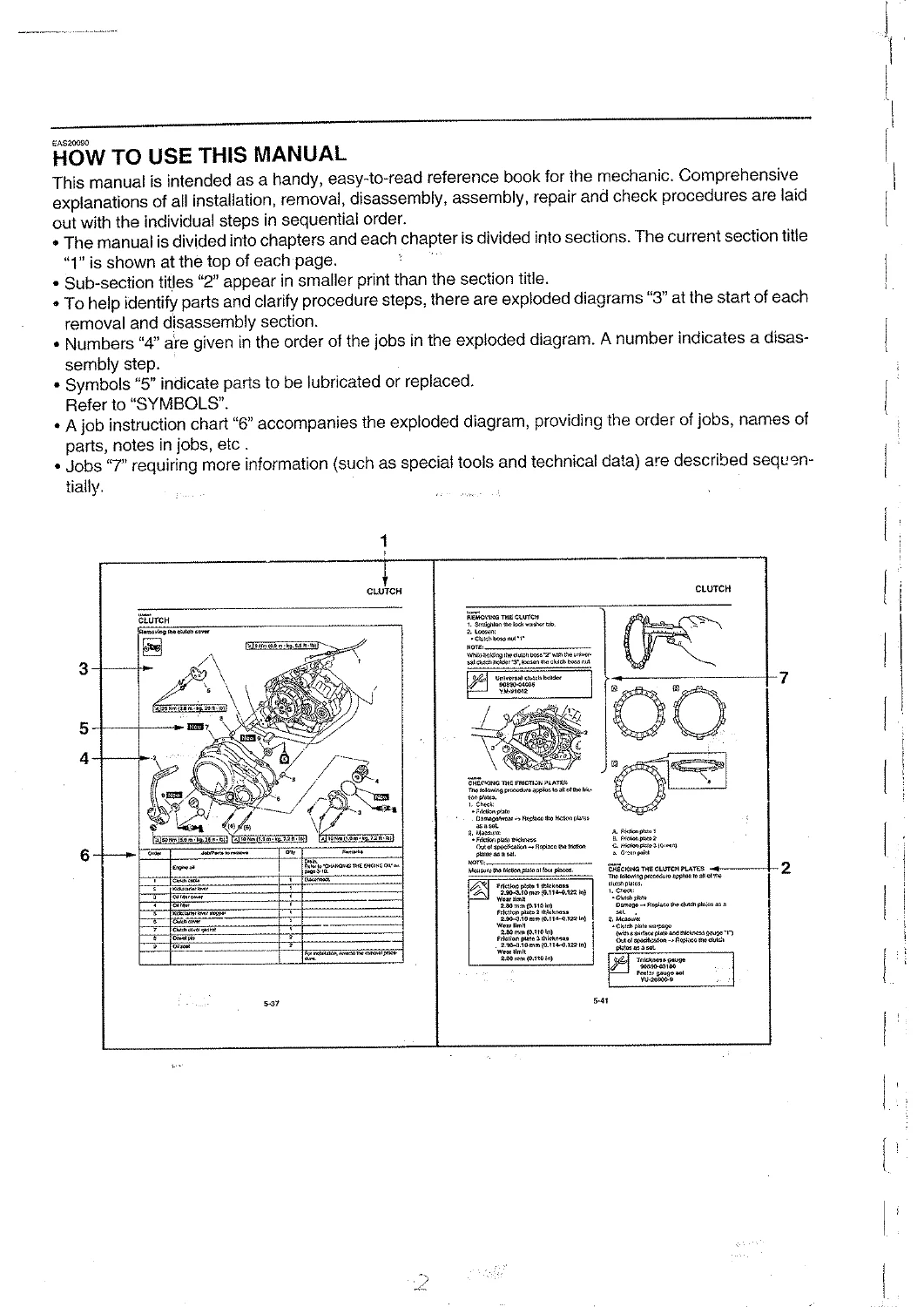
Yamaha FZ150i (29B1) Fuel Injection Motorcycle Service Manual (29B-F8197-E0)
Original price was: $36.95.$22.95Current price is: $22.95.
Official factory service manual for the fuel-injected Yamaha FZ150i (model 29B1). Contains complete workshop repair procedures, electronic fuel injection (FI) diagnostics, 149.8cc 4-stroke engine rebuild specifications, wiring diagrams, tightening torques, and chassis maintenance instructions.
Description
Yamaha FZ150i Service Manual
The Yamaha FZ150i (29B1) Fuel Injection Motorcycle Service Manual (29B-F8197-E0) is the official workshop reference manual produced by Yamaha Motor Company, Ltd. for dealership technicians, professional motorcycle mechanics, and DIY enthusiasts.
Engineered specifically for the single-cylinder, fuel-injected Yamaha FZ150i street motorcycle, this comprehensive manual provides complete technical guidance covering every component from electronic fuel injection diagnostics and complete engine teardown to suspension tuning, hydraulic brake servicing, and complete electrical wiring analysis.
File Details
Chapters Covered
- Chapter 1 — General Information: Motorcycle identification numbers (VIN and engine serial number locations), FI system outline and operational principles, workshop safety and disassembly guidelines, connector inspection routines, and factory special tool part numbers.
- Chapter 2 — Specifications: General vehicle dimensions, weights, and capacities; detailed engine specifications (bore, stroke, compression, clearances); chassis specifications; electrical component ratings; general and component-specific tightening torques; lubrication charts and oil flow diagrams; cooling system routing; and full-chassis cable routing schematics.
- Chapter 3 — Periodic Checks and Adjustments: Periodic maintenance and lubrication schedule tables; valve clearance adjustment (cold intake: 0.10–0.14 mm, exhaust: 0.20–0.24 mm); engine idling speed adjustment (1300–1500 r/min); CO density and exhaust gas volume adjustment using the FI diagnostic tool; throttle and clutch cable free play; compression pressure testing (510 kPa standard); engine oil and filter change; coolant replacement; hydraulic brake system bleeding; drive chain slack adjustment (20–40 mm); steering head adjustment; tire inspections; and headlight aim alignment.
- Chapter 4 — Chassis: Disassembly, inspection, and assembly of body panels, seat, and air filter case; front wheel and speedometer gear unit; rear wheel and drive hub; front hydraulic disc brake caliper and master cylinder rebuilds; rear drum brake and shoe wear limits; handlebar assembly; front telescopic fork overhaul and oil capacity (231.0 cm³); steering head ball/angular bearing service; rear shock absorber and relay arm linkage; swingarm; and final chain drive maintenance.
- Chapter 5 — Engine: Step-by-step procedures for engine removal and installation; cylinder head, camshaft, and rocker arm overhaul; valve and spring inspection; cylinder bore, piston, and piston ring end gap measurements; primary drive and balancer gears; wet multi-disc clutch overhaul; kickstarter ratchet and starter clutch; oil pump inspection; crankcase splitting; crankshaft runout limits; and 5-speed constant-mesh transmission rebuild.
- Chapter 6 — Cooling System: Radiator inspection, radiator cap pressure testing (93.2–122.6 kPa opening pressure), thermostat opening temperatures (80.5–83.5 °C), water pump disassembly, impeller shaft replacement, and coolant circuit diagrams.
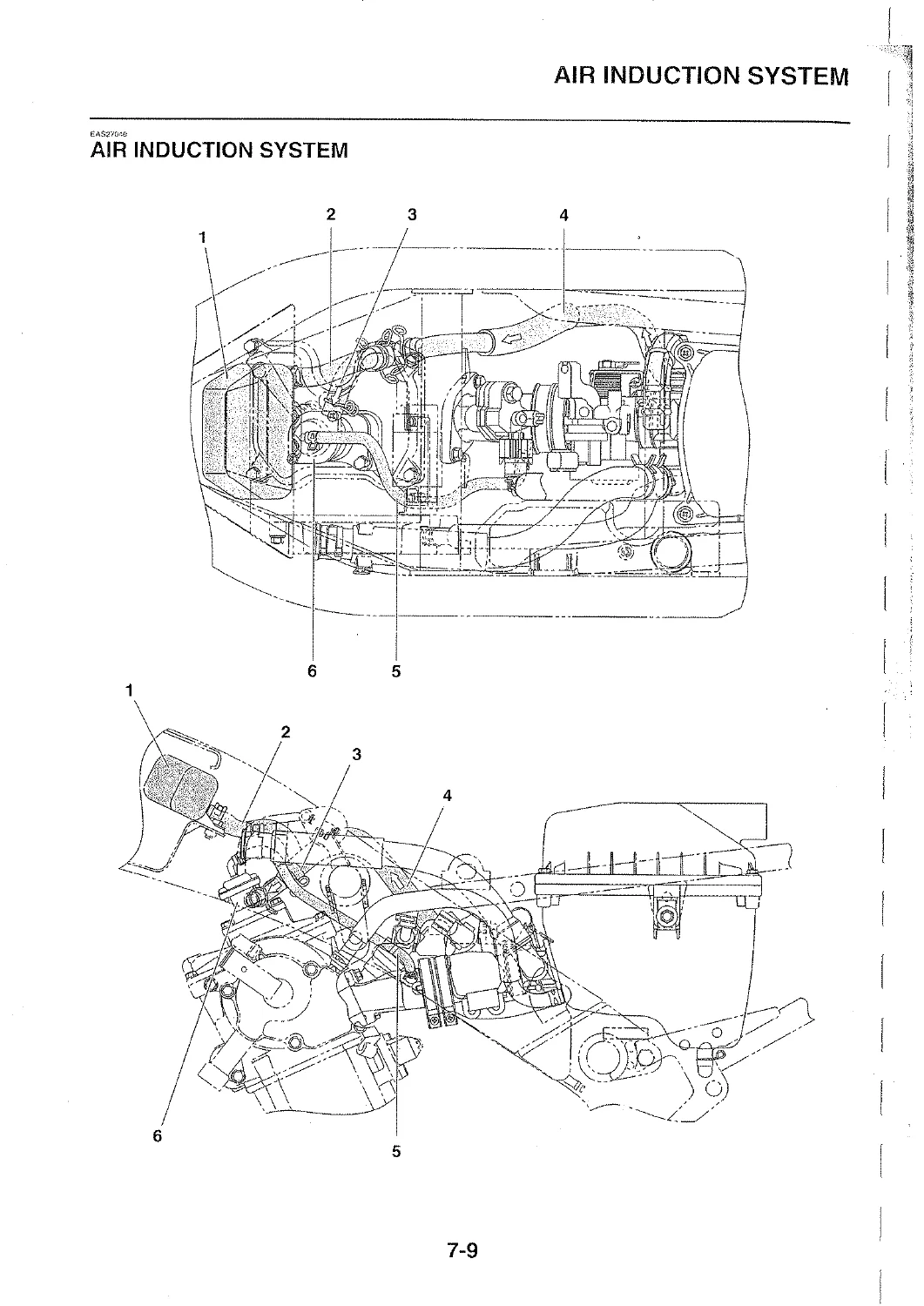
- Chapter 7 — Fuel System: Fuel tank removal; high-pressure fuel pump assembly inspection; Mikuni AC28 throttle body teardown; fuel injector testing; fast idle solenoid (FID); throttle position sensor (TPS); intake air pressure and temperature sensors; and air induction system (AIS) reed valve servicing.
- Chapter 8 — Electrical System: Transistorized coil ignition (TCI) circuit; AC magneto stator and rotor; semiconductor rectifier/regulator charging system; electric starter motor overhaul; relay operations; lighting, signaling, and switch tests; sensor resistance and voltage specifications; and FI system troubleshooting codes.
- Chapter 9 — Troubleshooting: Diagnostic flowcharts for engine starting failure, rough idling, poor medium/high-speed performance, faulty gearshifting, overheating, poor braking, and electrical circuit malfunctions.
Together, these chapters equip the technician with exhaustive mechanical data, structured step-by-step disassembly and assembly sequences, exploded view diagrams with torque callouts, and comprehensive fault-finding diagnostics required to maintain the Yamaha FZ150i in peak factory condition.
Electronic Fuel Injection & Electrical Highlights
The Yamaha FZ150i Service Manual details the operation and diagnostics of the advanced electronic fuel injection system. The ECU precisely controls the air-fuel ratio by processing signals from the crankshaft position sensor, intake air pressure sensor, intake air temperature sensor, throttle position sensor, coolant temperature sensor, and lean angle sensor.
Regulated by a built-in pressure regulator operating at 250 kPa (35.6 psi), fuel is delivered through the high-precision fuel injector directly into the intake tract. The manual provides full pin-out and resistance specifications, including instructions for connecting the Yamaha FI Diagnostic Tool (part number 90890-03182) to read error codes, monitor engine data in real time, and adjust exhaust CO density levels directly through the diagnostic port.
This section ensures that every repair, diagnostic procedure, and maintenance interval is executed according to strict factory engineering standards. Having the correct torque values, electrical resistance ranges, and assembly sequences protects engine internals and sensitive electronic injection components against premature wear and improper adjustments.
IMAGES PREVIEW
The manual is provided as an instant digital PDF download with no physical shipping delays. The high-resolution file is easily accessible across computers, tablets, and mobile smartphones, allowing you to quickly search for specific service steps, zoom into high-detail schematics, or print out individual workshop pages directly at your service bay.
Powertrain & Mechanical Rebuild Specifications
Whether performing routine maintenance or executing a full overhaul of the 149.8 cm³ liquid-cooled 4-stroke engine, this manual provides exact factory specifications and tolerances:
Cylinder & Piston: Standard cylinder bore of 56.985–57.010 mm with a 0.05 mm taper and out-of-round limit; piston-to-cylinder clearance of 0.020–0.045 mm (wear limit 0.15 mm); top and 2nd ring end gaps of 0.10–0.25 mm (limit 0.40 mm).
Valvetrain: SOHC 4-valve configuration with cold valve clearance set to 0.10–0.14 mm for intake and 0.20–0.24 mm for exhaust; intake valve head diameter of 19.40–19.60 mm and exhaust diameter of 16.90–17.10 mm; valve spring free length of 41.71 mm (limit 39.62 mm).
Clutch & Transmission: Wet multi-disc clutch with 2.90–3.10 mm friction plate thickness (wear limit 2.80 mm); clutch plate warpage limit of 0.20 mm; 5-speed constant-mesh gearbox with primary reduction ratio of 73/24 (3.042) and gear ratios: 1st (34/12), 2nd (30/16), 3rd (30/21), 4th (24/21), and 5th (22/23).
Fluid Capacities & Lubes: Total engine oil capacity of 1.15 L (1.00 L with filter change, 0.95 L oil change only) using SAE 20W-40 or 20W-50 API SG / JASO MA motor oil; cooling system total capacity of 0.79 L (radiator 0.38 L, reservoir 0.25 L) using 1:1 ethylene glycol mix; 12.0 L fuel tank.
Tightening Torques: Cylinder head M8 bolts (22 Nm / 16 ft-lb), M6 bolts (10 Nm / 7.2 ft-lb); camshaft sprocket bolt (30 Nm / 22 ft-lb); clutch boss nut (70 Nm / 50 ft-lb); primary drive gear nut (60 Nm / 43 ft-lb); generator rotor nut (70 Nm / 50 ft-lb); front axle nut (60 Nm / 43 ft-lb); and rear axle nut (80 Nm / 58 ft-lb).

Reviews
There are no reviews yet.