
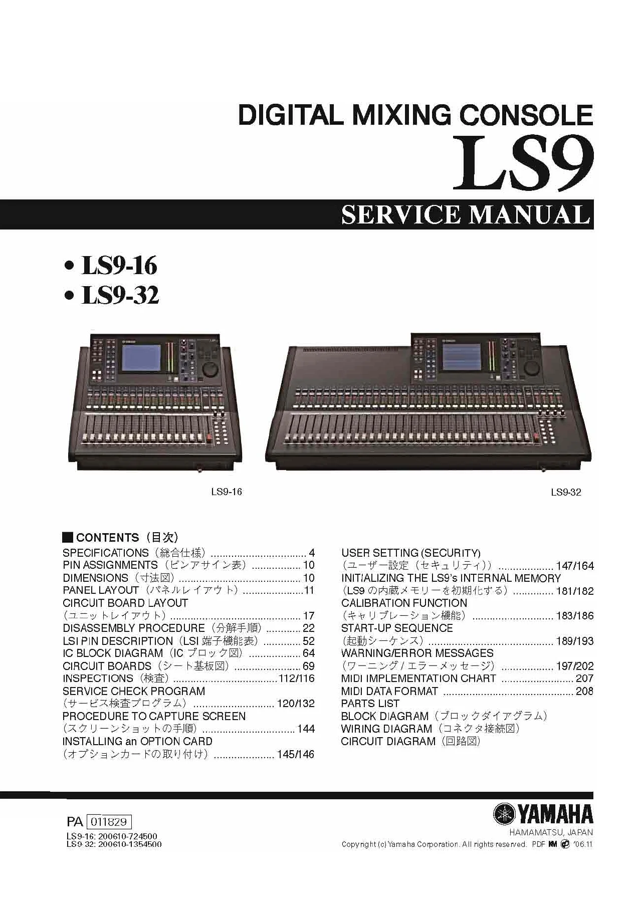
Yamaha LS9-16 LS9-32 Digital Mixing Console Service Manual & Schematic PDF
Original price was: $34.95.$20.95Current price is: $20.95.
Complete Yamaha LS9-16 and LS9-32 Digital Mixing Console Service Manual in PDF. Covers specifications, disassembly procedures, circuit board layouts, LSI pin descriptions, IC block diagrams, full schematics, parts list, service check program, calibration, start-up sequence, warning/error messages and MIDI data format.
Description
The Yamaha LS9-16 and LS9-32 Digital Mixing Console Service Manual is the complete technical reference used by authorized Yamaha retailers and service personnel to maintain, fault-find, disassemble and repair the LS9 series digital consoles. It covers both the 16-fader LS9-16 and the 32-fader LS9-32 in a single document, taking a technician from top-level specification tables right down to LSI pin functions, IC block diagrams and full board-level circuit schematics.
Because it is written for the workshop rather than the stage, this Yamaha LS9 service manual is the document that spells out how every board, connector, fader and fan inside the console is put together, how it comes apart, and what the correct service values and inspection criteria are once it is back together.
File Details
- Manual type: Service Manual (documentation supplied for authorized Yamaha retailers and service personnel)
- Brand: Yamaha
- Models covered: LS9-16, LS9-32 Digital Mixing Consoles
- Language: English and Japanese
- File format: PDF
- Page count: 208+ pages covering specifications, disassembly, circuit boards, parts and diagrams
Chapters Covered
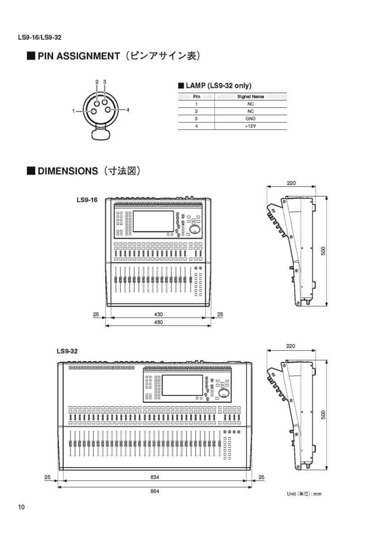
- Specifications – general, electrical, analog input/output, digital input/output, I/O slot and control I/O characteristics
- Pin Assignments
- Dimensions
- Panel Layout – top panel, rear panel and front panel
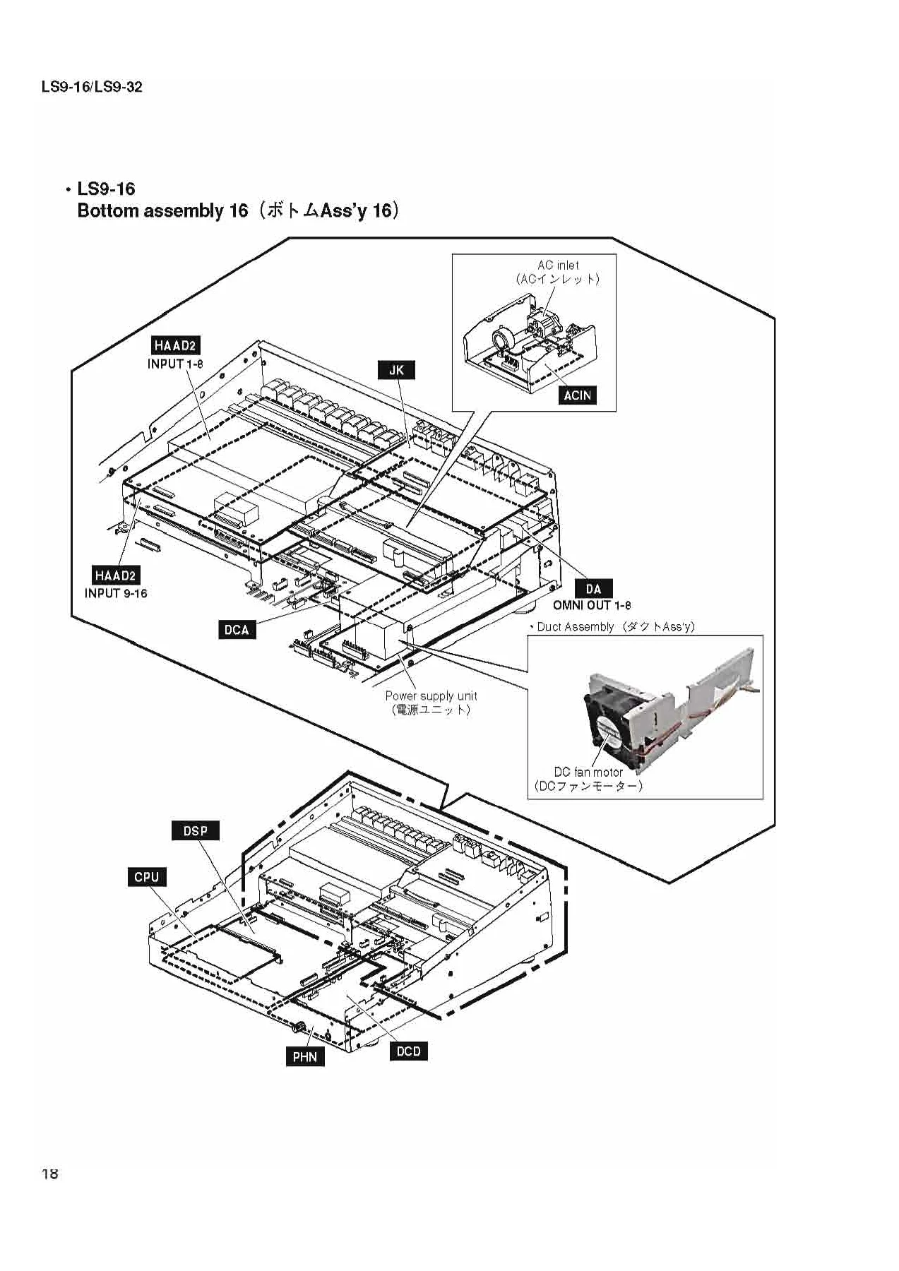
- Circuit Board Layout (unit layout)
- Disassembly Procedure – LS9-16 and LS9-32 bottom assembly, control panel assembly and LCD assembly
- LSI Pin Description
- IC Block Diagram
- Circuit Boards (sheet board diagrams)
- Inspections
- Service Check Program
- Procedure to Capture Screen
- Installing an Option Card
- User Setting (Security)
- Initializing the LS9 internal memory
- Calibration Function
- Start-Up Sequence
- Warning / Error Messages
- MIDI Implementation Chart
- MIDI Data Format
- Parts List
- Block Diagram
- Wiring Diagram
- Circuit Diagram
Taken together, these chapters form a complete service workflow. Specification and characteristic tables give the performance targets a repaired console has to meet. Panel, board and unit layout drawings show where every circuit board physically sits inside the chassis. The disassembly procedure breaks the work into numbered, screw-by-screw steps for each board, from the side panels and control panel assembly down to the CPU board, HAAD2 input boards, JK, DA, DCD, PHN, DSP/DSP32, DCA boards, AC inlet, power supply unit, duct assemblies, DC fan motor and the LCD assembly. The LSI pin description and IC block diagram chapters identify each large-scale IC by pin name and function, which is what turns a schematic into something you can actually probe. The inspections and service check program chapters provide the pass/fail criteria and the test routines – CPU SRAM, CPU SDRAM, backup battery, RTC, PLLP2, DSP6, DSP7, SLOT, WORD CLOCK, 2TR IN/OUT, MIDI, USB storage, NETWORK, RECORDER, LAMP, LCD, LED, switch, encoder, fader travel time and fader voltage level – used to confirm a board is healthy after replacement.
What a Technician Can Do With This Yamaha LS9 Service Manual
Disassembly and board replacement
Every board inside the LS9-16 and LS9-32 is covered by its own disassembly procedure with screw positions called out on rear, top and bottom views. You get step-by-step removal and refitting for the side panels, the control panel assembly, the CPU circuit board, the HAAD2 (1/2 and 2/2) input boards on the LS9-16 and the HAAD2 (1/4 through 4/4) boards on the LS9-32, the JK, DA, DCD, PHN and DCA boards, the DSP circuit board on the LS9-16 and the DSP32 board on the LS9-32, the AC top and bottom shields, the ACIN circuit board, the AC inlet assembly, the power supply unit, the duct assemblies, the DC fan motor, the FD and FD2 fader boards, the PNIN, STIN1 and STIN2 boards, and the ENC, PNMS, INV and PNDA boards inside the LCD assembly. Non-board parts that need to be carried over to a replacement – the earth sheet DA, the power switch knob, the fan holder and the control panel stays – are called out explicitly so nothing is lost in the swap.
Battery, board and MAC address handling
The manual covers lithium backup battery replacement on the CPU circuit board, including the physical removal method using the battery holder, and warns that internal settings must be saved to USB memory before the battery is disturbed. It also notes that the MAC address is stored on the CPU circuit board, so a board change alters the console MAC address – information that matters for anyone running an LS9 on a network.
Fault diagnosis and the service check program
The service check program is the most practical chapter for anyone troubleshooting a faulty LS9. It runs through CPU SRAM and SDRAM address and data bus checks, backup battery voltage, real time clock set and get, PLLP2 register read and write, DSP6 and DSP7 register and SIO connection checks, slot interface and slot power supply tests, WORD CLOCK PLL lock checks, 2TR digital loopback, MIDI loopback, USB storage recognition, network communication, recorder IC checks, LAMP output, LCD display patterns, LED all-on and colour-by-colour tests, switch and encoder input tests, fader travel time measurement and fader voltage level output tests. The manual explains what each check exercises and how the service PC application reports OK and NG, so a fault can be isolated to a specific board instead of swapping parts blindly.
Calibration and start-up recovery
Motor fader calibration, LCD contrast calibration, input port trim, output port trim and slot output trim are all documented with their target positions and step values – fader calibration cycles each selected fader through -infinity, -20 dB, 0 dB and +10 dB, while port trims are adjusted in 0.1 dB or 0.01 dB steps depending on the port. The start-up sequence chapter maps out Normal mode, Forced Factory Preset mode, Maintenance mode and the service Diag mode, explains how each is entered, and lists what is and is not operable while the console sits in Maintenance mode.
Option cards, USB, console security and MIDI
The manual covers installing a separately sold mini-YGDAI I/O card into slot 1 (LS9-16) or slots 1 and 2 (LS9-32), the user level and user authentication key security system, the console lock function, USB memory save and load operations, and the full MIDI implementation chart and MIDI data format for integrating the console into a larger system.
Who This Yamaha LS9 Service Manual Is For
This manual suits service engineers and repair shops working on Yamaha LS9 consoles, rental and installation companies maintaining their own inventory, broadcast and live sound departments with in-house technical staff, and technically capable owners who want to understand the internals of their console rather than send it away for every fault. The disassembly, LSI and circuit diagram content assumes bench-level repair skills and test equipment; the specification, panel layout and calibration chapters are useful to a wider technical audience.
Get the Yamaha LS9-16 and LS9-32 Service Manual
With the disassembly procedures, circuit board diagrams, LSI pin tables, schematics and the service check program all in one document, this Yamaha LS9 service manual gives you what you need to diagnose faults accurately, replace boards correctly, calibrate motor faders to spec and bring an LS9-16 or LS9-32 back to full working condition. Correct service procedures and correct service values are the difference between a repair that holds and a console that comes back a second time.
IMAGES PREVIEW
The manual is delivered as an instant PDF download after payment – no shipping, no waiting. It opens on any computer, laptop, tablet or phone, and any page can be printed for the bench so you can keep the relevant disassembly or schematic sheet next to the console while you work.


Reviews
There are no reviews yet.