
Yanmar 6RY17P-GV 6RY17Q-GV 6RY17P-EV Parts Catalog 2016 PDF Download
Original price was: $62.95.$44.95Current price is: $44.95.
Complete illustrated parts catalog for Yanmar 6RY17P-GV, 6RY17Q-GV and 6RY17P-EV diesel engines. Covers 162 figure groups from cylinder block to safety labels with exploded views, part numbers and quantities for every assembly.
Description
File Details
- Manual Type: Illustrated Parts Catalog
- Brand: Yanmar
- Models Covered: 6RY17P-GV, 6RY17Q-GV, 6RY17P-EV
- Language: English
- Document Number: 0CH10-M32801EN
- Edition: Revised edition, 2016
- Format: PDF
What This Yanmar Parts Catalog Contains
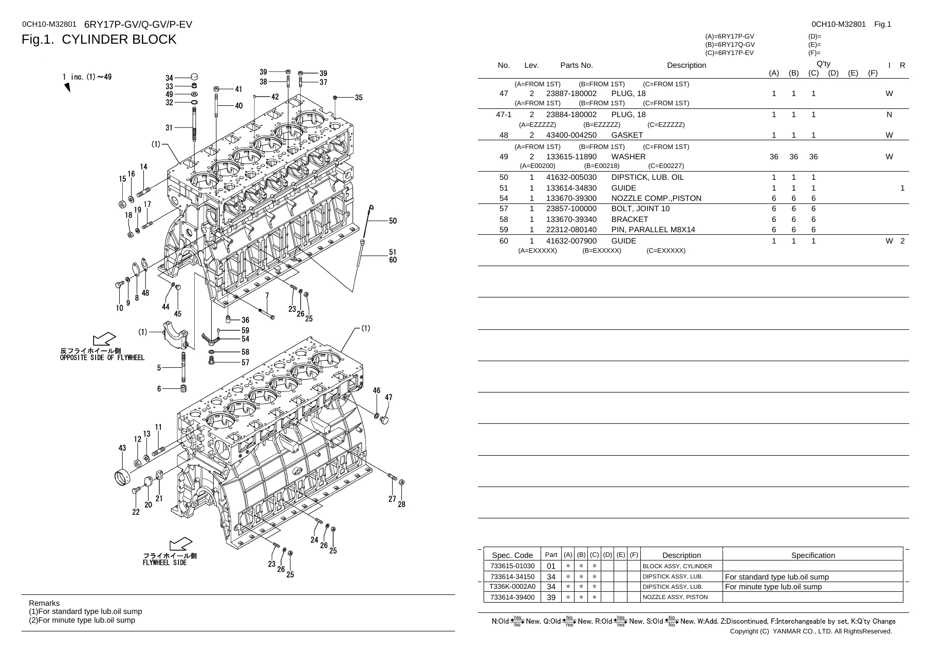
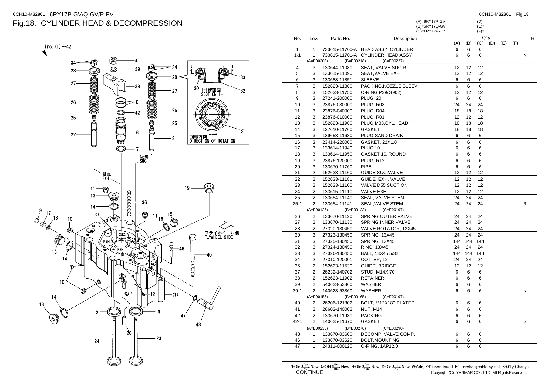
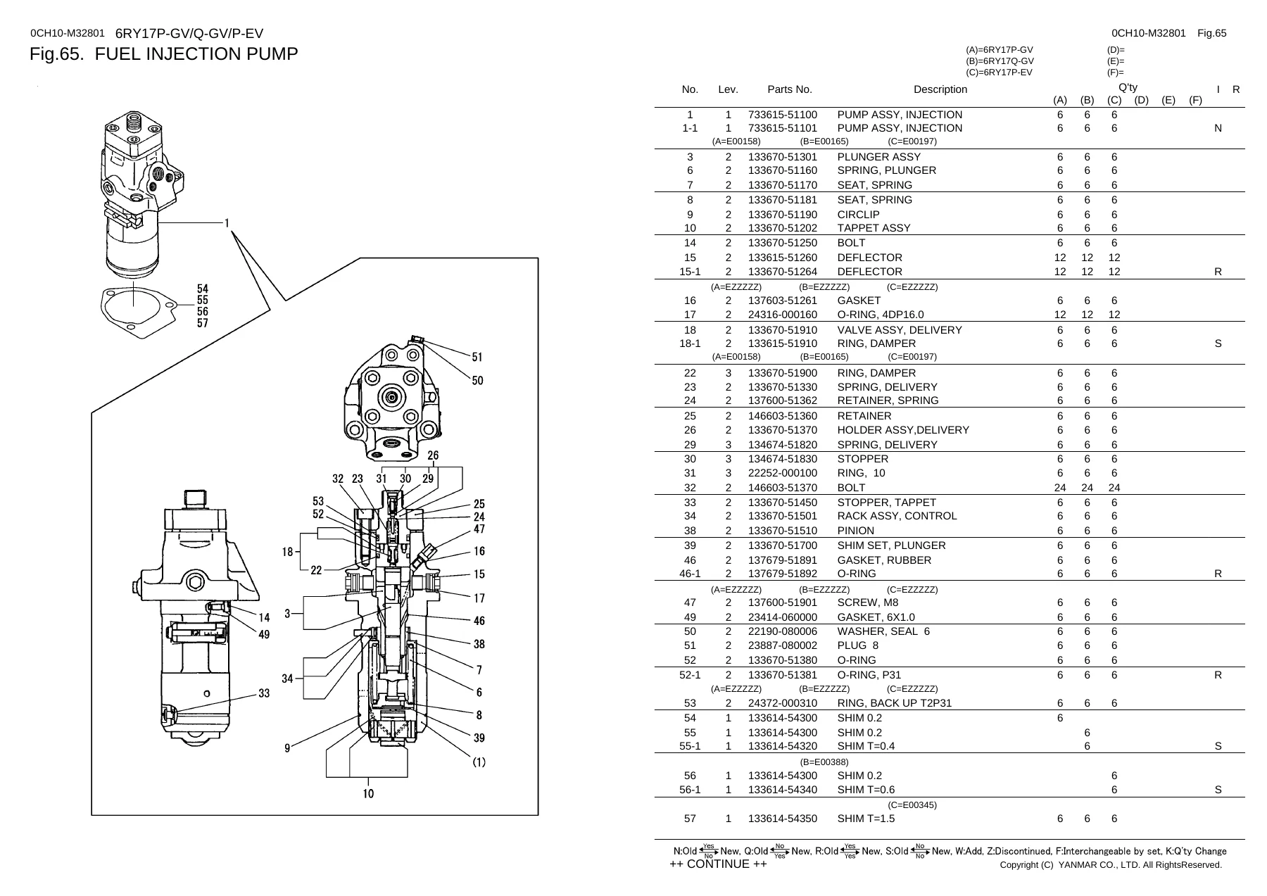
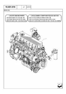
This is the complete illustrated parts catalog for the Yanmar 6RY17P-GV, 6RY17Q-GV and 6RY17P-EV diesel engines. It contains 162 figure groups covering every major assembly on these engines, from the cylinder block right through to the safety labels. Every figure page includes an exploded view drawing with numbered callouts, and each drawing is paired with a parts table listing the reference number, Yanmar part number, description and quantity required for the models covered.
The catalog was published as a revised edition in 2016 under document number 0CH10-M32801EN. It supersedes the earlier editions from 2002, 2004 and 2012. The contents apply to all three engine variants unless a figure or table is marked otherwise — where a part differs between the 6RY17P-GV, 6RY17Q-GV and 6RY17P-EV, the quantity columns and specification codes identify which variant uses which part.
Chapters Covered
- 1. Cylinder Block
- 2. Cylinder Liner & Head Gasket
- 3. Cylinder Side Cover (Control Side)
- 4. Cylinder Side Cover (Non-Control Side)
- 5. Gear Housing
- 6. Gear Housing Cover
- 7. Flywheel Housing
- 8. Cover (Front & Tachometer Driving Device)
- 9. Camshaft Chamber Cover
- 10. Camshaft Blind Cover
- 11. Lub. Oil Sump (Without Lub. Oil Emergency Exit)
- 12. Lub. Oil Sump (With Lub. Oil Emergency Exit)
- 112. (12A) Lub. Oil Sump (Minute Type)
- 13. Under Frame
- 14. Main Metal
- 15. Camshaft Metal
- 16. Breather
- 17. Fuel Pipe Cover
- 113. (17A) Scatter Protection Cover
- 18. Cylinder Head & Decompression
- 19. Bonnet & Valve Rocker Arm Support
- 20. Supply Air Bend
- 21. Supply Air Pressure Gauge Pipe & Regulating Valve
- 22. Exhaust Manifold (6RY17P-GV/6RY17Q-GV)
- 114. (22A) Exhaust Manifold (6RY17P-EV)
- 115. (22B) Fire Proof Cover
- 23. Camshaft & Working Valve Device
- 24. Idle Gear
- 25. Turbocharger (6RY17P-GV/6RY17Q-GV)
- 116. (25A) Turbocharger (6RY17P-EV)
- 26. Turbocharger Component Parts (6RY17P-GV/6RY17Q-GV)
- 117. (26A) Turbocharger Component Parts (6RY17P-EV)
- 27. Air Cooler
- 118. (27A) Air Cooler (2-Circuit Fresh/Fresh Water Cooling Spec.)
- 28. Air Duct (6RY17P-GV/6RY17Q-GV)
- 119. (28A) Air Duct (6RY17P-EV)
- 29. Crankshaft & Coupling
- 30. Flywheel
- 31. Damper
- 32. CG-Coupling
- 33. Piston & Connecting Rod
- 34. Lub. Oil Pump & Safety Valve
- 35. Lub. Oil Cooler
- 36. Lub. Oil Pressure Regulating Valve & Lub. Oil Pipe
- 37. Lub. Oil Strainer (Without Selector Cock)
- 120. (37A) Lub. Oil Strainer (With Selector Cock)
- 38. Lub. Oil By-Pass Strainer
- 39. Lub. Oil Thermostat
- 40. Lub. Oil Suction Pipe
- 41. Lub. Oil Pipe (Pump-Strainer)
- 42. Lub. Oil Pipe (Strainer-Cooler)
- 43. Lub. Oil Pipe (Thermostat-Engine)
- 44. Lub. Oil Wing Pump
- 121. (44A) Lub. Oil Wing Pump (Air Motor Spec.)
- 45. Lub. Oil Pipe (Wing Pump)
- 122. (45A) Lub. Oil Pipe (Wing Pump) (Minute Type Lub. Oil Sump Spec.)
- 123. (45B) Lub. Oil Pipe (Wing Pump) (Air Motor Spec.)
- 46. Lub. Oil Pipe (Front Shaft Drive)
- 47. Lub. Oil Pipe (Turbocharger) (6RY17P-GV/6RY17Q-GV)
- 124. (47A) Lub. Oil Pipe (Turbocharger) (6RY17P-EV)
- 48. Lub. Oil Press. Gauge Pipe
- 125-128. (48A-D) Clutch Hyd. Oil & Lub. Oil Pressure Gauge Pipe
- 49. Lub. Oil Pipe (Semi-Dry Return)
- 50. Cooling Fresh Water Pump
- 51. Cooling Sea Water Pump
- 52. Cooling Fresh Water Cooler
- 129. (52A) C.F.W. Cooler (2-Circuit Fresh/Fresh Water Cooling Spec.)
- 53. Cooling Water Strainer (Single)
- 54. Cooling Water Strainer (Duplex)
- 55. Kingston Valve
- 130. (55A) Cooling Water By-Pass Valve
- 56-64. Cooling Water Pipes
- 65. Fuel Injection Pump
- 66. Fuel Feed Pump
- 67. Fuel Priming Device
- 68. Fuel Feed Pump Driving Device
- 69. Fuel Injection Valve
- 70. Fuel Strainer (8 Micron) (Without Selector Cock)
- 71. Fuel Strainer (8 Micron) (With Selector Cock)
- 137/138. (71A/B) Fuel Strainer (8 Micron) (Potentiometer Spec.)
- 72. Fuel Strainer (100 Mesh: 20A)
- 73. Fuel Strainer (100 Mesh: 40A)
- 74. Fuel Sediment Tank
- 75. Fuel Sediment Strainer
- 76-83. Fuel Pipes
- 142. (83A) Fuel Overflow Pipe & Tank (Double-Walled F.I. Pipe Spec.)
- 84. Hydraulic Governor & Driving Device
- 143-146. (84A-D) Hyd. Governor Component Parts
- 85. Pneumatic Controller (Air Motor Spec.)
- 86. Fuel Cut Device (Solenoid)
- 147/148. (86A/B) Fuel Cut Device
- 87. Speed Control Device
- 88. Start/Stop Handle & Link
- 149. (88A) Start/Stop Handle Switch
- 89. Boost Compensator
- 150. (89A) Potentiometer Unit
- 151. (89B) Air Starter
- 90. Starting Motor (Earth Type)
- 152. (90A) Starting Motor
- 91. Starting Motor (Earth Float Type)
- 153. (91A) Starting Motor
- 92. Starter Switch & Battery Switch
- 93. Generator Driving Device
- 94. Generator
- 95. Generator Component Parts
- 96. Air Heater
- 97. Clutch
- 154. (97A) Clutch Lub. Oil Cooler Drain Pipe
- 155. (97B) Electronic Trolling Controller Box
- 98. Cooling Water Temp Switch
- 99. L.O. Press. Switch & Eng. Protect Device (4 Switch Spec.)
- 156. (99A) L.O. Press. Switch & Eng. Protect Device
- 100. L.O. Press. Switch & Eng. Protect Device (2 Switch Spec.)
- 157. (100A) L.O. Press. Switch & Eng. Protect Device
- 101. Remote Control Head
- 102. Wire Remo-Con Receiver (Gov.)
- 158. (102A) Wire Remote Control Receiver (Governor)
- 159. (102B) Wire Remote Control Receiver (Clutch)
- 103. Engine-Fixed Instrument Panel
- 160. (103A) Eng.-Fixed Inst. Panel
- 104. Hull-Fixed Instrument Panel
- 161. (104A) Sub-Panel
- 105. Sensor
- 106. Wire Harness
- 107. Thermometer
- 108. Tool (1) (Heavy Loading Spec.)
- 162. (108A) Tool (1) (For Domestic Spec.)
- 109. Tool (2)
- 110. Other Tool
- 111. Safety Label
Cylinder Block, Covers & Housing
Fig. 1 through Fig. 17A cover the foundation of the 6RY17 engine — the cylinder block, cylinder liners, head gaskets, side covers, gear housing and gear housing cover, flywheel housing, front cover with tachometer drive, camshaft chamber cover and camshaft blind cover. Also included are the standard and minute-type lub. oil sumps, under frame, main metal and camshaft metal, breather, and fuel pipe cover. Each figure gives you the exploded view of the casting, cover or housing with the correct bolt, stud, nut, washer and gasket part numbers so you can identify exactly what goes where.
Cylinder Head, Valve Train & Air System
Fig. 18 to Fig. 24 cover the cylinder head and decompression assembly, bonnet and valve rocker arm support, supply air bend, supply air pressure gauge pipe and regulating valve, exhaust manifold for both the 6RY17P-GV/6RY17Q-GV and the 6RY17P-EV, fire proof cover, camshaft and working valve device, and idle gear. These figures are essential when you need to identify valve guides, valve springs, rotators, rocker arm components, push rods and the exhaust manifold gaskets and hardware.
Turbocharger, Air Cooler & Air Duct
Fig. 25 through Fig. 28A break down the turbocharger installations for both engine families — TF15M for the GV models and TD13 for the EV model — with complete component parts lists covering housings, bearings, seals, compressor wheels, turbine shafts, V-clamps, silencers and pre-filters. The air cooler, 2-circuit fresh/fresh water cooler and air duct figures follow, with air heater and non-air heater configurations identified by specification code.
Crankshaft, Flywheel, Damper & Coupling
Fig. 29 to Fig. 33 cover the crankshaft and coupling, flywheel assembly with ring gear, viscous damper, CG-coupling options for CGM5507 through CGM5509 front drive arrangements, and the complete piston and connecting rod assembly including piston rings, piston pin, connecting rod bolts and crankpin metal options in standard and undersized/oversized dimensions.
Lubrication System
Fig. 34 to Fig. 49 cover the full lubrication circuit: lub. oil pump and safety valve, lub. oil cooler, pressure regulating valve and pipes, strainer with and without selector cock, by-pass strainer, thermostat, suction pipe, pump-to-strainer, strainer-to-cooler and thermostat-to-engine pipes. Also included are the wing pump and its piping for standard, minute-type sump and air motor specifications, front shaft drive pipe, turbocharger oil feed pipes for both engine families, semi-dry return pipe, and the complete set of clutch hydraulic and lub. oil pressure gauge pipes.
Cooling System
Fig. 50 to Fig. 64 cover the fresh water pump, sea water pump, fresh water cooler, 2-circuit fresh/fresh water cooler, single and duplex cooling water strainers, Kingston valve, cooling water by-pass valve, and every cooling water pipe in the circuit — pump inlet and outlet, head-to-exhaust manifold, exhaust manifold, pump-to-air cooler with and without by-pass valve, lub. oil cooler-to-fresh water cooler, lub. oil cooler-to-air cooler, clutch cooling water pipes for YXH and MGN clutch variants, cylinder drain pipe, and cooling water pressure gauge pipe.
Fuel System & Governor
Fig. 65 to Fig. 84D cover the fuel injection pump with plunger, delivery valve and control rack components, fuel feed pump, priming device, feed pump driving device, fuel injection valve, 8-micron and 100-mesh fuel strainers with and without selector cock, sediment tank and strainer, feed pump inlet and main pipes, injection pipes, fuel return and overflow pipes, pressure regulating valve, overflow tank, hydraulic governor assembly and its wire and air remote control component parts, pneumatic controller, fuel cut device, speed control device and boost compensator.
Starting, Charging & Electrical
Fig. 90 to Fig. 96 cover the starting motors in earth type and earth float type configurations, starter switch and battery switch, generator driving device, generator, generator component parts, and air heater. Fig. 105 to Fig. 107 cover the sensor locations, wire harness and thermometer arrangements across the engine.
Clutch, Remote Control & Instrumentation
Fig. 97 to Fig. 104A cover the clutch variants for YXH-240, YXH-250L and MGN90L, clutch lub. oil cooler drain pipe, electronic trolling controller box, cooling water temp switch, lube oil pressure switch and engine protect devices for both 4-switch and 2-switch specifications, remote control head, wire remote control receivers for governor and clutch, engine-fixed and hull-fixed instrument panels, sub-panel, potentiometer unit, and air starter.
Tools & Safety Labels
Fig. 108 to Fig. 111 cover the heavy loading tool set, domestic specification tools, tool set 2, other tools, and the complete safety label set with blow, caution and common labels.
Why This Yanmar Parts Catalog Matters
When you are rebuilding a 6RY17P-GV, 6RY17Q-GV or 6RY17P-EV, ordering the wrong part costs time and money. This catalog eliminates that risk. Every exploded view shows you exactly how the assembly goes together, and every parts table gives you the correct Yanmar part number and quantity for your specific engine variant. Whether you are replacing a failed turbocharger, resealing a fuel injection pump, chasing a cooling water leak, or simply doing a top-end overhaul, the correct part numbers are right here.
The catalog covers the standard engine as well as the many optional specifications — air motor starting, BX trolling, electronic trolling, minute-type lub. oil sump, semi-dry sump, 2-circuit fresh/fresh water cooling, double-walled fuel injection pipes, potentiometer specification, and more. The specification code tables at the bottom of many figure pages tell you exactly which part number applies to which engine variant and from which engine serial number a change took effect.
IMAGES PREVIEW
Instant PDF Delivery
This Yanmar 6RY17P-GV, 6RY17Q-GV and 6RY17P-EV parts catalog is delivered as an instant PDF download. No shipping, no waiting. The file works on any device — desktop, laptop, tablet or smartphone — and every page is printable so you can take the relevant figures straight to the workshop. Whether you are a Yanmar dealer, a marine engineer, a fleet maintenance technician or an owner-operator doing your own repairs, having the correct parts catalog on hand means you can identify, order and fit the right components with confidence.

Reviews
There are no reviews yet.