
Yanmar ViO20-2 US Excavator Service Manual PDF – Complete Workshop Guide
Original price was: $39.95.$24.95Current price is: $24.95.
Comprehensive Yanmar ViO20-2 (US) compact excavator service manual in PDF format. Covers engine, hydraulic system, undercarriage, controls, troubleshooting, specifications and full repair procedures for the 3TNE74-ENBV diesel engine and all major machine systems.
Description
Yanmar ViO20-2 (US) Excavator Service Manual – PDF Workshop Guide
This Yanmar ViO20-2 US Excavator Service Manual is a complete workshop reference for the ViO20-2 (US) compact excavator, covering service, repair and maintenance procedures across the engine, hydraulic system, undercarriage, controls, electrical equipment and work implements. Whether you are servicing a quick coupler model or a W/O quick coupler type, this PDF gives you the specifications, service standards, tightening torques, adjustment values and step-by-step procedures needed to keep the machine running to factory tolerances. The manual is written in English and structured as a full Yanmar service manual, with chapters dedicated to each system of the machine.
File Details
- Manual type: Service Manual (workshop / repair manual)
- Brand: Yanmar
- Model: ViO20-2 (US) compact excavator
- Engine covered: 3TNE74-ENBV
- Language: English
- Page count: 436 pages
- File format: PDF
Chapters Covered in the Yanmar ViO20-2 Service Manual
The Yanmar ViO20-2 US Excavator Service Manual is organised into eleven top-level chapters, each targeting a specific area of the machine:
- Chapter 1 – General Cautions for Maintenance Work: correct work practice, safety precautions, preparations, cautions for disassembly and reassembly, handling hydraulic equipment and piping, seal handling, correct installation of hydraulic hoses, hydraulic hose specifications and air release of hydraulic equipment.
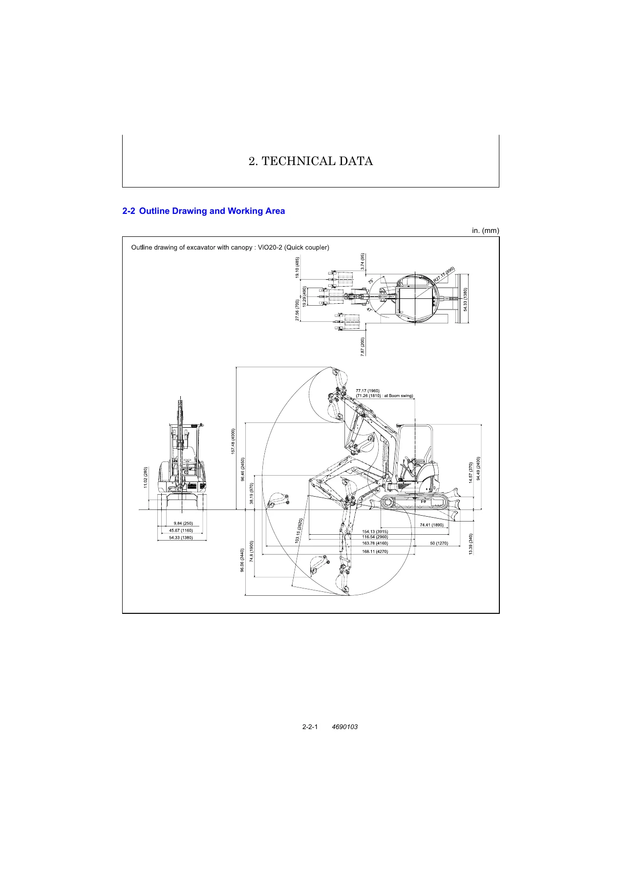
- Chapter 2 – Technical Data: specifications, outline drawing and working area, weight list of main parts, and lifting capacity list.
- Chapter 3 – Service Standards: machine performance, engine service values, undercarriage (rubber crawler and steel crawler specifications plus common specifications), controls, hydraulic equipment and hydraulic cylinder standards, implement (front attachments, blade moving device, bucket teeth) and the full list of tightening torques for machine, engine and general bolts and nuts.
- Chapter 4 – Engine: measurement, inspection and adjustment (compression pressure, valve clearance, V-belt tension, fuel injection valve and timing, idling speed, cooling system, sensors); measurement procedures, service data and corrective action for cylinder head, cylinder block, valve rocker arm, piston and piston rings, connecting rod, camshaft, crankshaft, gears and trochoid pump; precautions for reassembly; fuel injection system; and electrical equipment (starter motor, alternator, glow plug).
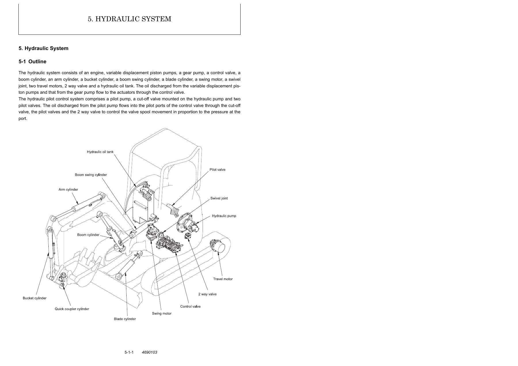
- Chapter 5 – Hydraulic System: outline of the hydraulic circuit, control valve operation, additional control valve operation, hydraulic circuit schematics for quick coupler and W/O quick coupler types, circuit operation for boom, arm, bucket, swing, boom swing, blade, travel, non-deviation travel, simultaneous operations, hydraulic P.T.O. and quick coupler, plus pressure adjustment of relief valves, swing brake valve and cut-off valve.
- Chapter 6 – Hydraulic Equipment: hydraulic pump, control valve, pilot valve, swing motor, travel motor and pilot check valve (quick coupler type) with structure, operation, disassembly, reassembly, service standards and troubleshooting.
- Chapter 7 – Adjustment and Repair: electrical equipment of machine and engine (parts layout, monitor and alarm systems, wiring diagram, engine start/stop and battery charging circuit, removal and reinstallation of engine, starter motor and fuel injection pump); undercarriage (crawler removal and reinstallation, idler and track roller disassembly and reassembly); controls (control train, mechanical control linkage, adjustment of travel levers, boom swing pedal, blade control lever, lock lever, travel alarm switch, P.T.O. pedal and accelerator lever); swing bearing; hydraulic equipment (removal and reinstallation of pump, control valve, swing motor, swivel joint, hydraulic cylinders, hydraulic oil tank and piping layout); and work implements.
- Chapter 8 – Periodic Inspection and Servicing: the periodic inspection and servicing schedule with daily, 50, 100, 200, 250, 400, 500, 1000 and 2000 hour intervals.
- Chapter 9 – Fuel, Lube Oil and Grease Recommended: the recommended fuel, engine oil, gear oil, hydraulic oil, grease and coolant for the machine, with capacities and temperature ranges.
- Chapter 10 – Troubleshooting: non-breakdowns explained, plus full troubleshooting charts for machine and engine, work implements, travel equipment, quick coupler type and electrical equipment on the panel (monitor lamps, hourmeter, water temp alarm, battery charge alarm, engine oil pressure alarm, warning buzzer, fuel level gauge).
- Chapter 11 – Reference Data: attachment specifications for the ViO20 bucket installation.
As a whole, the Yanmar ViO20-2 US Excavator Service Manual PDF is a full-coverage workshop reference. It starts with safety and handling cautions, moves through the technical data needed to plan any job, then delivers the standards and measurement values for both the machine and the engine. The bulk of the manual is spent on actual service work – measuring, inspecting, adjusting, disassembling, reassembling and troubleshooting – across the engine, hydraulic system, undercarriage, controls and work implements. Diagrams, exploded views, hydraulic circuit schematics and wiring diagrams sit alongside the procedures so that the technician can see the component being worked on while reading the steps. A separate periodic inspection chapter organises maintenance intervals, and the fuel, oil and grease chapter tells you exactly what to put back in the machine.
What This Yanmar ViO20-2 Service Manual Helps You Do
This manual supports the entire ownership and repair cycle of the ViO20-2 (US): routine periodic servicing, engine tune-ups and top-end work, hydraulic troubleshooting and component rebuilds, undercarriage repairs, control linkage adjustment, electrical fault finding, and full implement removal and reinstallation. It also covers the specific diagnostic values you need to check a suspect component – compression pressure at 300 rpm, valve clearances, relief valve set pressures, cylinder drift allowances, swing drift limits and travel speed timings – rather than just describing what the parts look like.
Having the correct procedures and service data on hand matters more than most owners realise. Torque values for cylinder head bolts, connecting rod bolts and hydraulic components are all listed, as are the wear limits that tell you when a part should be replaced instead of reused. Following these values is what separates a repair that lasts from one that fails early. The manual also warns you about the specific cautions for handling hydraulic equipment, seals and piping so that you do not introduce contamination or damage to the machine during a routine service.
Instant PDF Delivery
The Yanmar ViO20-2 US Excavator Service Manual is delivered as a PDF download the moment your order is complete. There is no shipping, no waiting and no physical media to keep track of. You can open it on a laptop, tablet or phone in the workshop, print the pages you need for a specific job, and keep the full 436-page manual on hand for every service and repair you carry out on the ViO20-2 (US).

Reviews
There are no reviews yet.