Trusted Business
Verified & Licensed
Virus Free Files
100% Safe Downloads
Secure Payment
SSL Protected
Instant Delivery
Available Immediately
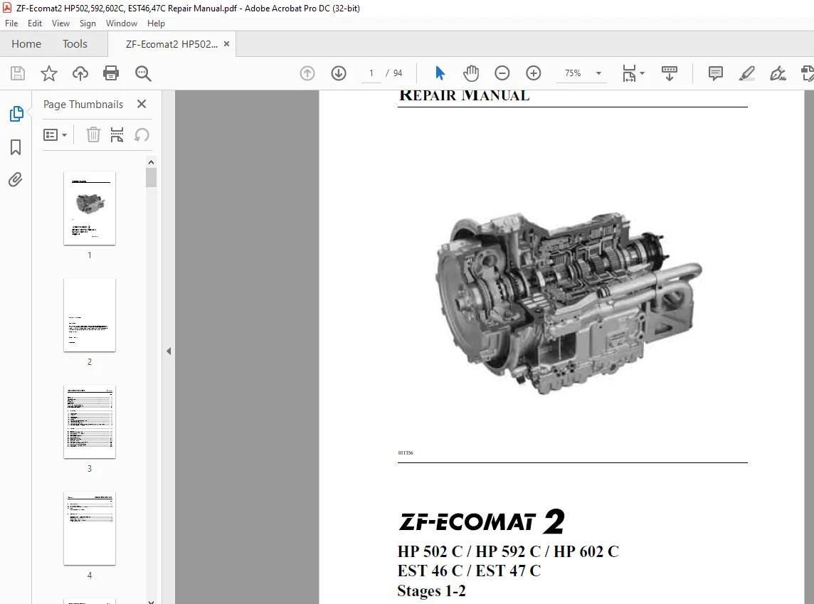
ZF-ECOMAT 2 HP502C HP592C HP602C EST 46C EST 47C Stage 1-2 Repair Manual 4149751601e – PDF DOWNLOAD
$28.95
ZF-ECOMAT 2 HP502C HP592C HP602C EST 46C EST 47C Stage 1-2 Repair Manual 4149751601e – PDF DOWNLOAD
Instant PDF Download
Available immediately
Save to Your Device
Download & keep forever
Antivirus Scanned
100% virus-free
Trusted Worldwide
175,000+ customers
Description
ZF-ECOMAT 2 HP502C HP592C HP602C EST 46C EST 47C Stage 1-2 Repair Manual 4149751601e – PDF DOWNLOAD
FILE DETAILS:
ZF-ECOMAT 2 HP502C HP592C HP602C EST 46C EST 47C Stage 1-2 Repair Manual 4149751601e – PDF DOWNLOAD
Language : English
Pages : 94
Downloadable : Yes
File Type : PDF
IMAGES PREVIEW OF THE MANUAL:
DESCRIPTION:
ZF-ECOMAT 2 HP502C HP592C HP602C EST 46C EST 47C Stage 1-2 Repair Manual 4149751601e – PDF DOWNLOAD
PREFACE:
This repair manual is intended for skilled personnel trained by ZF Friedrichshafen AG to carry out
mainte- nance and repair work on ZF products.
- This manual deals with the standard ZF product in accordance with the state of development on the
date of issue. - However, due to continuing development of the product, repair work might require work practices and
test or adjustment data not contained in this manual. - We recommend that work done on your ZF product is carried out only by skilled mechanics who have
had their practical and theoretical knowledge updated on a regular basis at our After-Sales Service
training centers.
Service points equipped by ZF Friedrichshafen AG all over the world offer you:
1. Continually trained personnel
2. Specified equipment, e.g. special tools
3. Genuine ZF spares, to our latest specifications
All work performed at these service points is carried out conscientiously and with utmost care.
- Repair work carried out at ZF service points is subject to the contractual conditions prevailing in
the individual case. - Damage resulting from work performed by non-ZF personnel in an improper and unprofessional manner
and any consequential costs are excluded from the con- tractual liability agreement. Exclusion of
liability also applies if genuine ZF spares are not used.
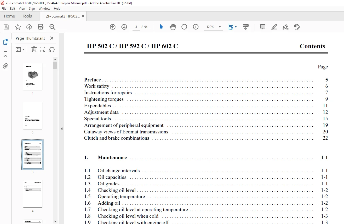
TABLE OF CONTENTS:
ZF-ECOMAT 2 HP502C HP592C HP602C EST 46C EST 47C Stage 1-2 Repair Manual 4149751601e – PDF DOWNLOAD
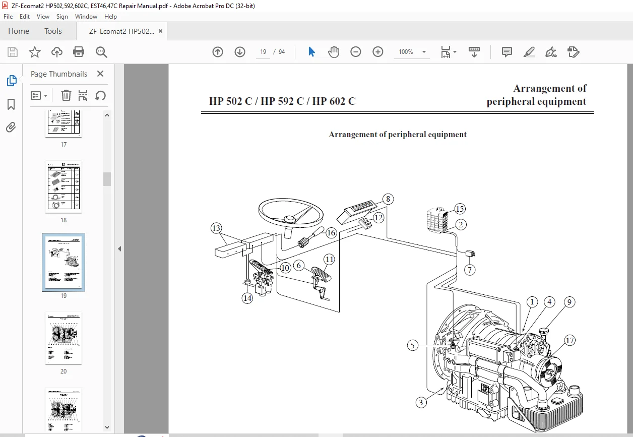
REPAIR MANUAL, Stages 1-2................................................................................... 1
	HP 502 C / HP 592 C / HP 602 C EST 46 C / EST 47 C Stages 1-2, 4149 751 601e............................ 1
	Contents................................................................................................ 3
	Preface................................................................................................. 5
	Important information................................................................................... 6
	Instructions for repairs................................................................................ 7
	Instructions for carrying out repairs................................................................... 8
	Tightening torques...................................................................................... 9
	Expendables.............................................................................................11
	Adjustment data.........................................................................................12
	Special tools...........................................................................................15
	Arrangement of HP peripheral equipment..................................................................19
	Cutaway view............................................................................................20
	ZF Ecomat transmission, 4-speed version.................................................................20
	ZF Ecomat transmission, 5 & 6-speed version.............................................................21
	Clutch combination......................................................................................22
	1. Maintenance..........................................................................................23
		1.1 Oil change intervals............................................................................23
		1.2 Oil capacities..................................................................................23
		1.3 Oil grade.......................................................................................23
		1.4 Checking oil level..............................................................................24
		1.5 Operating temperature...........................................................................24
		1.6 Adding oil......................................................................................24
		1.7 Checking oil level at operating temperature.....................................................24
		1.8 Checking oil level when cold....................................................................25
		1.9 Checking oil level with engine off..............................................................25
		1.10 Checking oil level on versions with heat ex-changer higher than center line of transmission....25
		1.11 Changing oil at operating temperature..........................................................26
	2. Overhaul.............................................................................................27
		2.1 Renewing filter.................................................................................27
		2.2 Renewing retarder solenoid valve................................................................29
		2.3 Renewing accumulator solenoid valve.............................................................30
		2.4 Renewing accumulator............................................................................31
		2.5 Renewing temperature sensor.....................................................................32
		2.6 Renewing output sensor..........................................................................33
		2.6.1 Renewing retarder resistor....................................................................37
		2.7 Removing and fitting oil pan....................................................................39
		2.8 Renewing turbine sensor.........................................................................43
		2.9 Renewing complete hydraulic control module......................................................49
		2.10 Changing complete oil level display............................................................54
		2.11 Renewing pulse sensor..........................................................................58
		2.12 Renewing output flange and/or shaft seal.......................................................59
		2.13 Pressure tests.................................................................................63
		Pressure table:.....................................................................................64
	3. Troubleshooting......................................................................................65
		3.1 Terminal tester concept.........................................................................65
		3.2 1PO1 138 153 test cable.........................................................................66
		Resistance measurements.............................................................................67
		Table of tolerance Temperature sensor NTC - Sensor B14..............................................68
		Characteristics Resistance/Temperature..............................................................68
		DIAGNOSTIC TOOL Installation and menus..............................................................69
			Contents........................................................................................71
			Preface.........................................................................................72
			Safety notice...................................................................................73
			Contents of Testman / System components.........................................................74
			Testman software installation...................................................................75
			Additional settings.............................................................................76
			Installation of the diagnosis software Connecting up a programming tool.........................77
			DPA 04 I description............................................................................78
			DPA 04 I programming Selecting COM port.........................................................79
			Starting the Testman............................................................................80
			Start-up logo...................................................................................81
			Product menu / Contents.........................................................................82
			Repair aid / Contents...........................................................................83
			Technical data..................................................................................84
	4. Diagrams.............................................................................................85
		Hydraulic circuit diagram without NBS 4149 700 026/1................................................85
		Hydraulic circuit diagram with NBS 4149 700 026/2...................................................86
		EST 46 C, Connection diagram 6029 729 041/1.........................................................87
		EST 46 C, Connection diagram 6029 729 041/2.........................................................88
		EST 47 C, Connection diagram 6029 729 041/3.........................................................89
		EST 47 C, Connection diagram 6029 729 041/4.........................................................90
		EST 46 / 47 C, Electrical circuit diagram 6029 729 040..............................................91
		EST 46 / 47 C, Pin pattern 6029 729 072.............................................................92
		Hydraulic 2, Position locked........................................................................93
		Hydraulic 1, Position opened........................................................................94
Need help? Contact: [email protected]
PLEASE NOTE:
- This is the SAME exact manual used by your dealers to fix your vehicle.
- The same can be yours in the next 2-3 mins as you will be directed to the download page immediately after paying for the manual.
- Any queries / doubts regarding your purchase, please feel free to contact [email protected]
S.V