ZF-ECOMAT 2 plus HP 502 HP 592 HP 602 Installation, Functions, & Initial Start-Up Technical Manual 4149765103 – PDF DOWNLOAD
$27.95
ZF-ECOMAT 2 plus HP 502 HP 592 HP 602 Installation, Functions, & Initial Start-Up Technical Manual 4149765103 – PDF DOWNLOAD
Description
ZF-ECOMAT 2 plus HP 502 HP 592 HP 602 Installation, Functions, & Initial Start-Up Technical Manual 4149765103 – PDF DOWNLOAD
FILE DETAILS:
ZF-ECOMAT 2 plus HP 502 HP 592 HP 602 Installation, Functions, & Initial Start-Up Technical Manual 4149765103 – PDF DOWNLOAD
Language : English
Pages : 186
Downloadable : Yes
File Type : PDF
IMAGES PREVIEW OF THE MANUAL:
DESCRIPTION:
ZF-ECOMAT 2 plus HP 502 HP 592 HP 602 Installation, Functions, & Initial Start-Up Technical Manual 4149765103 – PDF DOWNLOAD
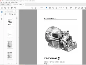
Transmission brief description:
ZF Ecomat transmissions from ranges HP 502,
HP 592, and HP 602 can be used in multiple appli- cations in commercial and special vehicles. It is
possible to select between 5 or 6-speed transmissions to cover all requirements – from fitting in a
city bus to use in a long-distance coach. To ensure the broadest possible range of applications,
Ecomat transmissions can be fitted with many auxiliaries.
They have been designed to comply fully with today’s requirement of traffic safety and optimum
economy.
HP 592, and HP 602 offer the following advantages:
engine and driveline.
Substantial cost savings are also achieved by extending the service life of wheel brake linings.
restriction of converter operation to the initial driving phase.
safety.
fic conditions or even with drivers who have no
practice with it.
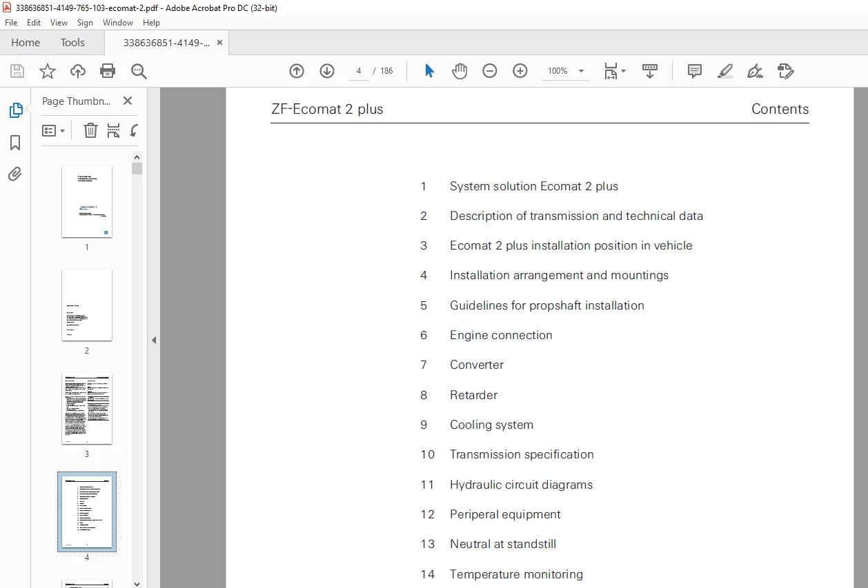
TABLE OF CONTENTS:
ZF-ECOMAT 2 plus HP 502 HP 592 HP 602 Installation, Functions, & Initial Start-Up Technical Manual 4149765103 – PDF DOWNLOAD
Technical Manual ZF-ECOMAT 2 plus...................................................................................  1
	4149 765 103....................................................................................................  1
	Copyright by ZF Edition: 2004-12................................................................................  2
	Important Information...........................................................................................  3
	Contents........................................................................................................  4
	1 System solution Ecomat 2 plus................................................................................. 10
		1.1 System solution Ecomat 2 plus (with CAN)................................................................ 10
		1.2 System solution Ecomat 2 plus........................................................................... 11
		1.3 System solution Ecomat 2 plus........................................................................... 12
	2 Description of transmission and............................................................................... 14
		2.1 Transmission brief description.......................................................................... 14
		2.2 Transmission structure and auxiliaries.................................................................. 16
		2.3 Transmission ratios and powerflow diagram............................................................... 18
		2.4 Torque assignment - vehicle weight...................................................................... 20
		2.5 Torsional vibration in driveline – inertia.............................................................. 21
		2.6 Weights and inertia torque values....................................................................... 25
			2.6.1 Coaxial output without heat exchanger J08......................................................... 25
			2.6.2 Coaxial output with heat exchanger J01............................................................ 26
			2.6.3 Coaxial output with heat exchanger J05............................................................ 27
			2.6.4 Coaxial output with heat exchanger J10............................................................ 28
			2.6.5 Angle drive 80° without offset, with heat exchanger J05........................................... 29
			2.6.6 Angle drive 80° without offset, with heat exchanger J10........................................... 30
			2.6.7 Angle drive 80° RHD (with right offset), with heat exchanger J05.................................. 31
			2.6.8 Angle drive 80° RHD (with right offset), without heat exchanger J08............................... 32
		2.7 Clutch combinations..................................................................................... 33
	3 Ecomat installation position in vehicle....................................................................... 34
	4 Installation arrangement and mountings........................................................................ 35
		4.1 Transmission flange-mounted on engine................................................................... 35
	5 Guidelines for propshaft installation......................................................................... 36
		5.1 Permissible rotational irregularity..................................................................... 36
		5.2 Permitted resultant deflection angle for................................................................ 37
		5.3 The permitted resultant flexure angle for all........................................................... 38
		5.4 Single-section propshafts............................................................................... 39
		5.5 Multi-section propshafts................................................................................ 39
		5.6 Maximum permissible propshaft length.................................................................... 40
	6 Engine connection............................................................................................. 41
		Variant 1................................................................................................... 42
		Variant 2................................................................................................... 43
		6.1 ZF Scope of delivery.................................................................................... 44
		6.2 Engine connection inspection............................................................................ 44
		6.3 Engine connection: Further information.................................................................. 44
		6.4 Engine connection drawings.............................................................................. 45
		6.5 Overview converter-circuit cover........................................................................ 47
	7 Converter..................................................................................................... 48
		7.1 Torque converter: Description........................................................................... 48
		7.2 Converter functions..................................................................................... 48
		7.3 Getting the right torque converter for your............................................................. 50
		7.4 Torque converter diagram................................................................................ 51
		7.5 Torque converter basic curves........................................................................... 53
			W360*TPC210*MUE2.43..................................................................................... 54
			W360*TPC262*MUE2.40..................................................................................... 55
			W360*TPC300*MUE2.36..................................................................................... 56
			W360*TPC342*MUE2.27..................................................................................... 57
			W360*TPC390*MUE2.17..................................................................................... 58
			W390*TPC392*MUE2.20..................................................................................... 59
			W390*TPC487*MUE1.98..................................................................................... 60
			W390*TPC615*MUE1.83..................................................................................... 61
	8 Retarder...................................................................................................... 62
		8.1 Structure and function of retarder...................................................................... 62
		8.2 Retarder action......................................................................................... 63
		8.4 Retarder and engine brake............................................................................... 64
		8.5 Retarder activation variants............................................................................ 65
			8.5.1 Permitted variants “foot request” without......................................................... 66
			8.5.2 Permitted variants “foot request”................................................................. 67
			8.5.3 Permissible retarder activation variants.......................................................... 68
				Retarder activation variants........................................................................ 69
	9 Cooling system................................................................................................ 70
		9.1 Design of cooling system................................................................................ 70
			9.1.1 Release criteria for temperature measurements..................................................... 70
			9.1.2 Limit temperature values for oil temperature...................................................... 71
			9.1.3 Cooling system with retarder...................................................................... 71
			9.1.4 Cooling system without retarder................................................................... 72
		9.2 Position of transmission oil cooler..................................................................... 73
		9.3 Cooler fitted on transmission........................................................................... 73
		9.4 Layout with oil cooler separate from.................................................................... 73
		9.5 Cooling water circuit................................................................................... 74
		9.6 Specification for transmission heat..................................................................... 77
		9.7 Required performance of cooling water and............................................................... 77
		9.8 Transmission fill with auxiliary cooling................................................................ 78
		9.9 Transmission oil sump cooling........................................................................... 79
		9.10 Temperature measurements in bus........................................................................ 80
			9.10.1 Measurement conditions / Retarder test........................................................... 80
			9.10.2 Measurement retarder cycles...................................................................... 80
			9.10.3 Calculation...................................................................................... 80
			9.10.4 Explanation of water temperature................................................................. 81
			9.10.5 Temperature measuring points..................................................................... 81
	10 Transmission specification................................................................................... 83
		10.1 Installation position.................................................................................. 84
			10.1.1 Flange-mounted installation position............................................................. 84
		10.2 Heat exchanger arrangement............................................................................. 85
			10.2.1 Coaxial output, heat exchanger at rear, accumulator horizontal on left........................... 85
			10.2.2 Coaxial output, heat exchanger at rear, accumulator rear transverse.............................. 86
			10.2.3 Coaxial output or 80° angle drive RHD (with axial offset),....................................... 87
			10.2.4 Angle drive 80° LHD (without axial offset), heat exchanger horizontal on left,................... 88
			10.2.5 Coaxial output, heat exchanger vertical on right, accumulator horizontal on left................. 89
			10.2.6 Coaxial output, vertical heat exchanger on right, accumulator rear transverse.................... 90
			10.2.7 Coaxial output, heat exchanger separate from transmission, accumulator direct mounting........... 91
				10.2.7.1 Cooler connection piece with threaded connection........................................... 92
		10.3 Oil pan................................................................................................ 93
			10.3.1 Deep oil pan, 4149 131 002....................................................................... 93
			10.3.2 Deep oil pan; left- and right-hand connection prepared, 4149 131 006............................. 94
			10.3.3 Deep oil pan, auxiliary cooling, 4149 131 024.................................................... 95
			10.3.4 Flat oil pan, 4149 131 010....................................................................... 96
			10.3.5 Flat oil pan; left- and right-hand connection prepared, 4149 131 009............................. 97
		10.4 Oil filling............................................................................................ 98
			10.4.1 Oil filling <K 01>............................................................................... 98
			10.4.2 Oil filling <K 02>, <K 04>, <K 05>............................................................... 99
			10.4.3 Oil filling <K03>, <K 06>........................................................................100
			10.4.4 Oil filling <K 09>...............................................................................101
		10.5 Output.................................................................................................102
			10.5.1 Coaxial output...................................................................................102
			10.5.2 80° angle drives.................................................................................103
			10.5.3 Output flange 80° angle drive LHD................................................................104
			10.5.4 Ecomat output flange; coaxial and angle drive 80° RHD with axial offset..........................105
	11 Hydraulic circuit diagrams...................................................................................106
		11.1 Hydraulic description..................................................................................107
		11.2 Hydraulic diagram (with Bus Stop Neutral / NBS)........................................................108
	12 Peripheral equipment.........................................................................................109
		12.1 Speed range selector - push button switch..............................................................109
		12.2 CAN range selector.....................................................................................112
		12.3 Load sensor A 3........................................................................................113
			12.3.1 Function.........................................................................................113
			12.3.2 Load sensor drawing..............................................................................114
		12.4 PWM-Signal.............................................................................................115
			12.4.1 Calibration of the PWM Signal, Positive..........................................................115
			12.4.2 Sensing ratio....................................................................................116
			12.4.3 Signal Spezification.............................................................................116
		12.5 Additional temperature sensor A6 for...................................................................117
		12.6 Temperature display A5.................................................................................118
		12.7 Kick down switch.......................................................................................119
		12.8 Pressure switch S7 - NBS (Neutral when.................................................................120
		12.9 Changeover relay, e.g. range selector relay............................................................121
	13 Neutral at standstill........................................................................................122
		13.1 Description............................................................................................122
		13.2 Connection diagram (electric)..........................................................................123
		13.3 Neutral at Bus Stop - display..........................................................................124
			13.3.1 NBS active display via digital signal............................................................124
	14 Temperature monitoring.......................................................................................125
		14.1 Temperature information via CAN........................................................................125
		14.2 Temperature information via temperature................................................................125
		14.3 Temperature information from DM1 note..................................................................125
		14.4 Temperature warnings...................................................................................125
		14.5 Addtional temperature sensor A6........................................................................126
		14.6 Temperature display gauge A5...........................................................................127
		14.7 Resistance characteristics - Temperature sensor........................................................128
	15 Electronic automatic control system..........................................................................129
		15.1 Function description...................................................................................129
		15.2 Intended standard functions............................................................................129
		15.3 Functions available on request.........................................................................130
		15.4  Installation requirements.............................................................................130
		15.5 Technical data of EST 146 / 147........................................................................131
		15.6 Installation drawings..................................................................................133
			15.6.1 Installation drawing EST 146.....................................................................133
			15.6.2 Installation drawing EST 147.....................................................................134
		15.7 Current circuit diagrams...............................................................................135
			15.7.1 Current circuit diagram EST 146 / EST 147 with CAN and digital range selector....................135
			15.7.2 Current circuit diagram EST 146 / EST 147 with CAN, with CAN range selector......................136
			15.7.3 Current circuit diagram EST 146 / EST 147 without CAN(NEng), with digital range selector.........137
		15.8 Pin pattern............................................................................................138
		15.9 Connection diagrams....................................................................................139
			15.9.1 Current circuit diagram EST 146 / EST 147 with CAN and digital range selector, page 1............139
				Current circuit diagram EST 146 / EST 147 with CAN and digital range selector, page 2...............140
				Current circuit diagram EST 146 / EST 147 with CAN and digital range selector, page 3...............141
				Current circuit diagram EST 146 / EST 147 with CAN and digital range selector, page 4...............142
			15.9.2 Current circuit diagram EST 146 / EST 147 with CAN and CAN range selector, page 1................143
				Current circuit diagram EST 146 / EST 147 with CAN and CAN range selector, page 2...................144
				Current circuit diagram EST 146 / EST 147 with CAN and CAN range selector, page 3...................145
				Current circuit diagram EST 146 / EST 147 with CAN and CAN range selector, page 4...................146
			15.9.3 Current circuit diagram EST 146 / 147 without CAN (NEng), with digital selector range, page 1....147
				Current circuit diagram EST 146 / 147 without CAN (NEng), with digital selector range, page 2.......148
				Current circuit diagram EST 146 / 147 without CAN (NEng), with digital selector range, page 3.......149
				Current circuit diagram EST 146 / 147 without CAN (NEng), with digital selector range, page 4.......150
		15.10 Function description EST 146 / 147....................................................................151
		15.11 ZF-Diagnosis systems..................................................................................158
			15.11.1 ZF-Diagnosis protocols..........................................................................158
			15.11.2.1 ZF-Testman pro................................................................................158
			15.11.2.2 Flash code output EST 146/147.................................................................161
		15.12 HST 46 auxiliary control unit.........................................................................163
			15.12.1 Operating manual for HST 46.....................................................................163
			15.12.2 Technical data of HST 46........................................................................163
			15.12.3 Dimensions of HST 46............................................................................164
		15.13 Block diagram EST 146.................................................................................165
		15.14 Block diagram EST 147.................................................................................166
	16 Wiring.......................................................................................................167
		16.1 Complete wiring - Standard.............................................................................167
		16.2 Complete wiring - with junctions.......................................................................167
		16.3 Wiring connection......................................................................................167
		16.4 Wiring specifications..................................................................................168
	17 ZF documentation.............................................................................................170
		17.1 ZF documentation with CAN..............................................................................170
			17.1.1 Components.......................................................................................170
			17.1.2 Identification and engine compatibility data.....................................................171
		17.2 ZF documentation without CAN...........................................................................172
			17.2.1 Components.......................................................................................172
			17.2.2 Identification and engine compatibility data.....................................................173
		17.3 Oil level check........................................................................................174
			17.3.1 Oil level check prior to first commissioning;....................................................174
			17.3.2 Oil level check prior to first commissioning;....................................................175
			17.3.3 Oil level check prior to first commissioning;....................................................176
	18 Calculations and conversion tables...........................................................................177
		18.1 Driveline design.......................................................................................177
		18.2 Collective formulae for retarder and cooler............................................................178
		18.3 Conversion tables......................................................................................179
			18.3.1 Units of length..................................................................................179
			18.3.2 Units of area....................................................................................179
			18.3.3 Units of volume..................................................................................180
			18.3.4 Units of energy..................................................................................180
			18.3.5 Units of mass....................................................................................181
			18.3.6 Force units......................................................................................182
			18.3.7 Power units......................................................................................183
			18.3.8 Temperature conversions..........................................................................183
			18.3.9 Moment of inertia conversion factors.............................................................184
		18.4 Torque.................................................................................................184
		18.5 List of dynamic tire radii.............................................................................184
	19 Oil grades and oil filters...................................................................................186
		19.1 List of Lubricants TE-ML 14............................................................................186
		19.2 Purity of medium.......................................................................................186
		19.3 Oil filter.............................................................................................186
Questions? Email us: [email protected]
PLEASE NOTE:
- This is the SAME exact manual used by your dealers to fix your vehicle.
- The same can be yours in the next 2-3 mins as you will be directed to the download page immediately after paying for the manual.
- Any queries / doubts regarding your purchase, please feel free to contact [email protected]
S.V