ZF ERGOPOWER 4/6 WG-190/210 REPAIR INSTRUCTION MANUAL PDF
$27.95
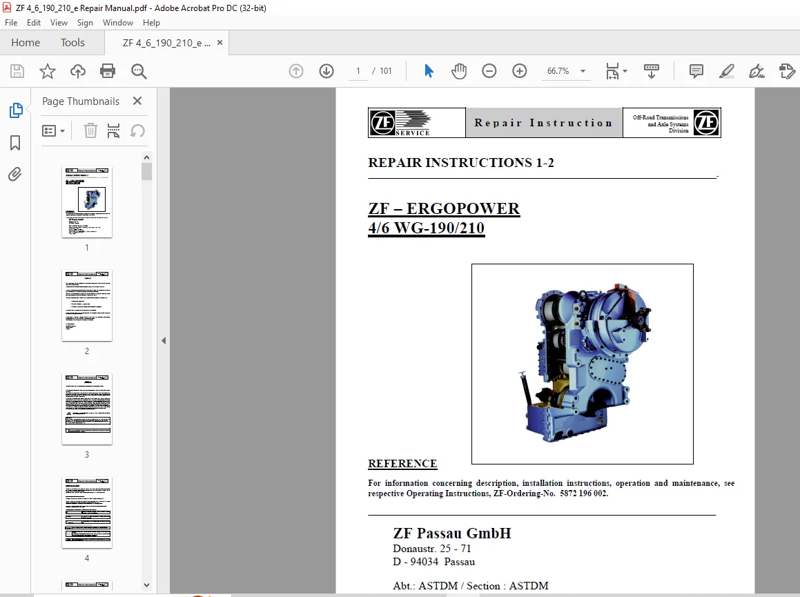
ZF ERGOPOWER 4/6 WG-190/210 REPAIR INSTRUCTION MANUAL – PDF DOWNLOAD
Description
ZF ERGOPOWER 4/6 WG-190/210 REPAIR INSTRUCTION MANUAL – PDF DOWNLOAD
FILE DETAILS:
ZF ERGOPOWER 4/6 WG-190/210 REPAIR INSTRUCTION MANUAL – PDF DOWNLOAD
Language : English
Pages : 101
Downloadable : Yes
File Type : PDF
IMAGES PREVIEW OF THE MANUAL:
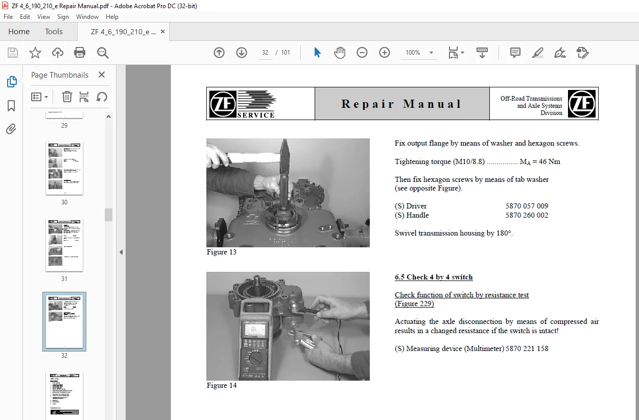
TABLE OF CONTENTS:
ZF ERGOPOWER 4/6 WG-190/210 REPAIR INSTRUCTION MANUAL – PDF DOWNLOAD
ZF – ERGOPOWER TRANSMISSION 6 WG-210 0
Preface 2
General Information 3
Denomination of Standard Dimensions 5
Conversion Table 6
Torque Limit ZF Standard 148 7
Technical Data 4 WG 190/210 36
Technical Data 6 WG 210 38
Repair Instruction 1-2 0
1 Filter change 8
1 1 Tools and Torque Limits 8
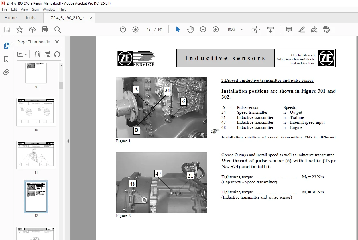
2 Inductive sensors 10
2 1 Torque limits 11
2 2 Hints 10
3 Bypass- and relief valve 0
3 1 Tools and Torque Limits 14
4 Shift unit 0
4 1 Tools and Torque Limits 19
5 Lock-up valve 24
5 1 Hints 24
5 2 Tools and Torque limits 25
6 Output shaft seals 28
6 1 Tools and Torque Limits 28
7 Temp Sensor 13
Tables 4WG 190/210 40
Layout 4 WG-190/210 40
Installation view -Direct Installation – Front view 41
Installation view – Direct Installation – Front view 42
Installation view – Standard version – Rear view 43
Installation view with disc brake – Rear view 44
Installation view with 1 and 2 Power take-off – Rear view 45
Schedule of measuring points and connections 46
Oil circuit diagram (Forward 1st speed) 48
Electro-hydraulic control with proportional valves 50
Power flow Forward/Reverse speeds 52
Fully automatic control EST-37 circuit diagram – 6029 717 040 – 53
Controller DW-3 55
Controller ERGO II 56
Type plate 57
Tables 6 WG 190/210 58
Layout 6 WG-210 58
Layout with retarder 59
Installation view separate installation with Retarder – Front view 60
Installation view separate installallation with Retarder – Side view 61
Installation view separate installation with Retarder – Rear view 62
Installation view separate installation with disk brake and without WK – Front view 63
Installation view separate installation with disk brake and without WK – Side view 64
Installation view separate installation with disk brake and without Wk – Rear view 65
Installation view separate installation with axle disconnection and WK – Front view 66
Installation view separate installation with axle disconnection and WK – Side view 67
Installation view separate installation with axle disconnection and WK – Rear side 68
Installation view separate installation with interaxle differential and WK – Front view 69
Installation view separate installation with interaxle differential and WK – Side view 70
Installation view separate installation with interaxle differential and Wk – Rear view 71
Installation view separate installation with axle disconnection and WK-valve – side mounting – Front view 72
Installation view separate installation with axle disconnection and WK-Valve – side mounting – Side view 73
Installation view separate installation with axle disconnection and WK-valve – side mounting – Rear view 74
Installation view direct installation with axle disconnection – Front view 75
Installation view direct installation with axle disconnection – Side view 76
Installation view direct installation with axle disconnection – Rear view 77
Schedule of measuring points and connections without WK 78
Oil circuit diagram without WK Forward 1st speed 80
Schedule of measuring points and connections with WK 82
Oil circuit diagram with WK Forward 1st speed 84
Schedule of measuring points and connections with WK and Retarder 86
Oil circuit diagram with WK and Retarder Forward 1st speed 88
Gearbox diagram 91
Power flow – Forward speeds 92
Power flow – Reverse speeds 93
Electro-hydraulic shift control with Proportional valves 94
Fully automatic control unit EST-37 circuit diagram Standard (6029 717 039) 96
Fully automatic control unit EST-37 circuit diagram crane vehicle (6029 701 057) 98
Controller VTS-3 100
Pushbutton switch D7 101
DESCRIPTION:
ZF ERGOPOWER 4/6 WG-190/210 REPAIR INSTRUCTION MANUAL – PDF DOWNLOAD
PREFACE:
- This documentation has been developed for skilled staff trained by the ZF Passau for the repair and
maintenance works on ZF-units. - Documented is a ZF-serial product representing the design state at the time of the edition.
- However, due to further technical developments of the product, the repair of the unit at your disposal could
require different steps as well as different adjustments and testing specifications. - Therefore, we recommend to commit your ZF-product to foremen and technicians whose practical and
theoretical training is permanently updated in our after-sales service school.
The service stations established world-wide by the Zahnradfabrik Friedrichshafen are offering to you:
1. Continuously trained staff
2. Prescribed facilities, e.g. special tools
3. Genuine ZF-spare parts meeting the latest state of development
ZF ERGOPOWER 4/6 WG-190/210 REPAIR INSTRUCTION MANUAL PDF:
S.V 2/04/2025