
ZF Ergopower 4 WG-160 Facelift Transmission Repair Manual 5871.151.002
Original price was: $32.95.$19.95Current price is: $19.95.
Disassembly and reassembly manual for the ZF ERGOPOWER 4 WG-160 Facelift powershift transmission, covering clutches KV/KR/K1–K4, converter and pump, electro-hydraulic control, PTO shaft, output flanges, and parking-brake variants.
Description
File Details
- Manual type: Repair manual (disassembly and reassembly)
- Brand / model: ZF ERGOPOWER 4 WG-160 Facelift
- Language: English (translation of the German original)
- Page count: 171
- File format: PDF
- Document number: 5871.151.002 en (cover); inner pages also marked 5871 152 002
- Design level: 2008/04
- Edition: 3. Edition 2010/09
- Publisher: ZF Friedrichshafen AG, ZF Services, Passau (Section MAIP21)
- Related operating instructions (not included): ZF Order No. 5872 151 002
What this ZF Ergopower 4 WG-160 Facelift Transmission Repair Manual 5871.151.002 covers
The ZF Ergopower 4 WG-160 Facelift Transmission Repair Manual 5871.151.002 is a workshop-level teardown and rebuild guide for one current ZF production design of the 4 WG-160 Facelift powershift. It is written for specialized staff and follows the actual sequence used to strip a unit on an assembly truck, then put every clutch pack, shaft, pump, converter connection, output flange, and electro-hydraulic control back together with the listed special tools.
This document does not replace the separate Operating Instructions (ZF Order No. 5872 151 002) for description, daily operation, or routine maintenance. ZF also notes that continuous technical upgrading and design options can require differing steps; those options are expected to be handled from the perspective views in the matching spare-parts list. Vehicle-maker installation and commissioning specifications still apply when the rebuilt unit goes back into the machine.
Transmission layout the technician will work on
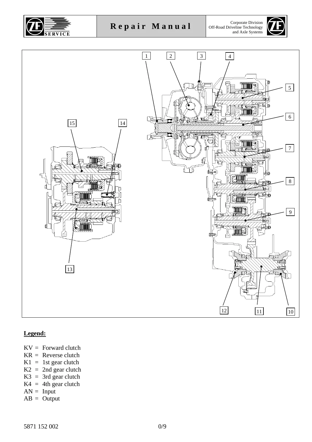
Configuration pages identify the 4 WG-160 as a converter powershift with input via prop shaft, a coaxial engine-dependent PTO, transmission pump, converter safety / back-pressure valve, and six clutch shafts: KV (forward), KR (reverse), K1 (1st), K2 (2nd), K3 (3rd), and K4 (4th). Output can leave on the rear side or on the converter side. Optional parking-brake hardware on the output flanges includes FSG-75, FSG-90/110, and FSG-88, plus a converter-side flange with axle disconnection.
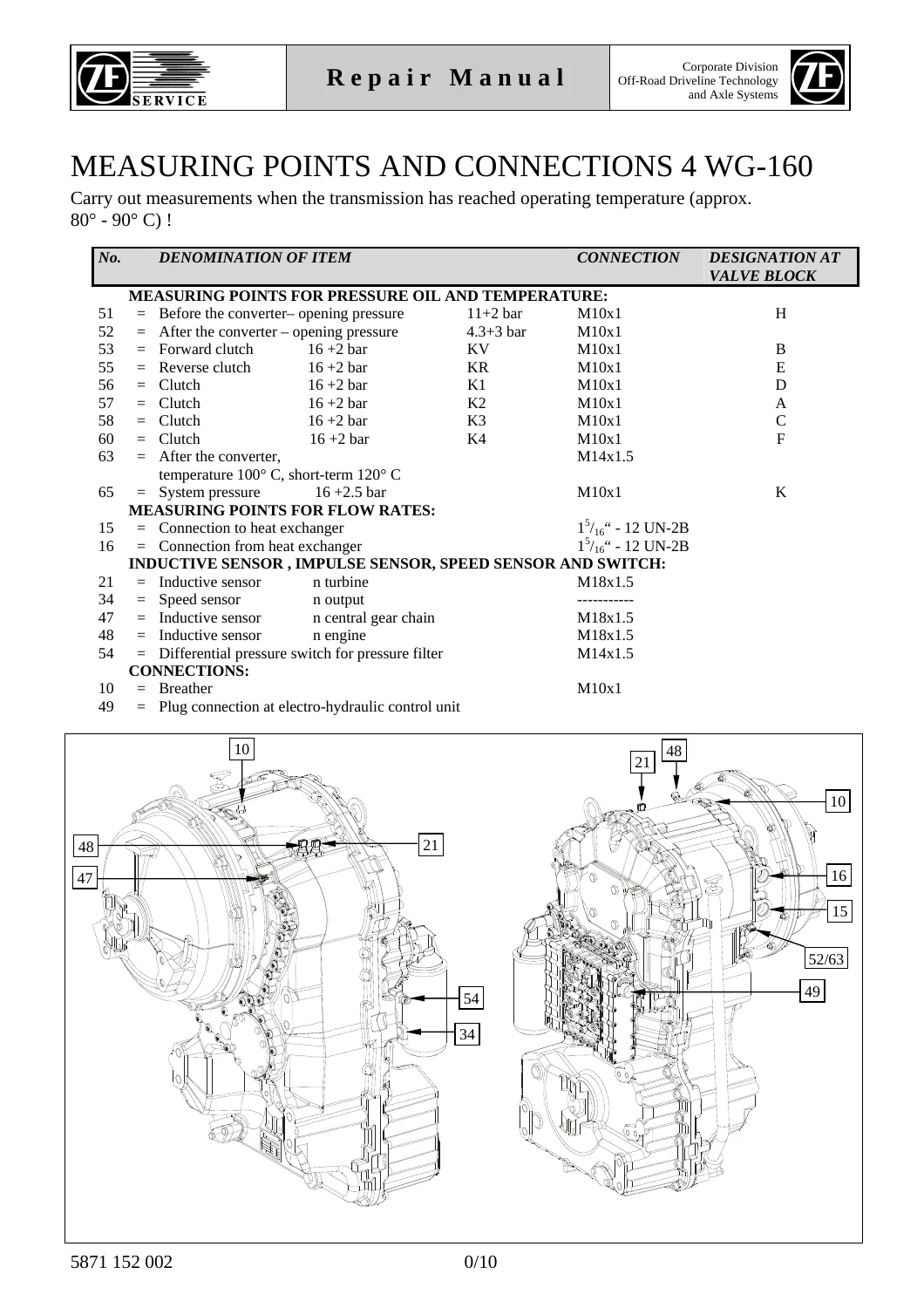
Measuring-point data is given for use once the transmission has reached operating temperature of approximately 80°–90° C. Before-converter opening pressure is listed as 11+2 bar (port H). After-converter opening pressure is 4.3+3 bar. Forward, reverse, and gear-clutch test points are 16+2 bar (valve-block letters B, E, D, A, C, F for KV, KR, K1, K2, K3, K4). System pressure is 16+2.5 bar at port K. After-converter temperature is specified at 100° C, short-term 120° C. Heat-exchanger connections, inductive sensors for turbine / central gear chain / engine speed, an output speed sensor, a filter differential-pressure switch, the breather, and the electro-hydraulic control plug are all located on the housing drawings.
Approved oils are those on ZF List of Lubricants TE-ML 03. Oil specification and fill quantity for a given unit are taken from that unit’s identification plate, which also carries transmission type, unit number, ZF parts-list number, overall ratio, and customer number—the same data required when ordering spare parts.
Chapters Covered
- Preface
- General workshop practice, industrial-safety notes, CAUTION / DANGER symbols
- Denomination of standard dimensions
- Conversion table
- Tightening torques for screws (ZF Standard 148)
- Labeling of identification plate and notes on spare parts ordering
- Configuration of transmission (schematics and cutaway)
- Measuring points and connections
- Notes on oil grade and oil fill quantity
- Special tools (WS/1 … 9)
- Commercial tools (WH/1 … 5)
- 1. Disassembly – Electro-hydraulic control and ZF fine filter (replaceable filter): removal of filter; removal of electric gear-shift control
- 2. Disassembly – Inductive sensor, Hall sensor, breather, oil filler and oil drain plug
- 3. Disassembly – Engine connection, oil pressure pump, converter back-pressure valve and temperature sensor: direct mount; remote mount; oil pressure pump; converter back-pressure valve
- 4. Disassembly – Emergency steering pump: version without pump; version with pump
- 5. Disassembly – Outputs and closure parts pump shaft (PTO-shaft): converter-side flange; output-side flange without parking brake; FSG-75; FSG-90/110; FSG-88; converter-side flange with axle disconnection; PTO-shaft closure parts
- 6. Removal of input shaft, output shaft, pump shaft (PTO-shaft) and clutches
- 7. Disassembly – Clutches KV / KR / K1 / K2 / K3 / K4, input and output shaft
- 8. Reassembly – Clutches KV / KR / K1 / K2 / K3 / K4, input and output shaft
- 9. Installation of input shaft, output shaft and clutches
- 10. Assembly – Outputs and closure parts pump shaft (PTO-shaft), including all listed flange and parking-brake versions
- 11. Reassembly – Engine connection, oil pressure pump, converter back-pressure valve and temperature sensor
- 12. Reassembly – Emergency steering pump
- 13. Reassembly – Inductive sensor, Hall sensor, breather, oil filler and oil drain plug
- 14. Reassembly – Electro-hydraulic control with proportional valves (with and without emergency steering pump)
- 15. Parking brake – functional characteristics and maintenance instructions for M-90, FSG-75, FSG-90/FSG-110, and FSG-88
Taken together, those chapters give a technician a complete strip-and-rebuild path for the Facelift 4 WG-160 rather than a general theory book. Filter head and proportional-valve control come off first, then sensors and breathers, then the engine interface (direct or remote), pump and converter valve, optional emergency steering pump, output flanges and PTO closures, and finally the clutch shafts. Rebuild runs the same hardware in reverse, with dedicated fixture and rolling-tool steps for each clutch and for shaft installation.
Workshop rules, tools, and torque data printed in the manual
General pages insist on cleanliness, plastic-hammer separation of sealed covers, proper pullers for bearings, replacement of seal rings, locking plates and split pins, and dry cleaning only of organic (paper) friction disks. Fluid seals and Molykote are not permitted on the control part. Parts may be heated only in a furnace or with an electric drier, then reseated after cooling. Screw torques follow ZF Standard 148 unless a procedure states otherwise; the printed chart covers metric coarse and fine threads from M4 through M39 for property classes 8.8, 10.9 and 12.9 at μ tot. = 0.12.
Special-tool lists include the assembly truck with tilting device (5870 350 000), holding fixtures, clamping angles, belt spanner, TX 40 and TX 27 sockets, adjusting screws, eye bolts, HP hand pump and Minimess coupling for hydraulic work on flanges, press bushes, rolling tools, grab sleeves and rapid grips for clutch teardown, cut-off device, assembly fixtures, drivers for seals and flanges, and a reducing adapter used on the valve block. Commercial tools listed alongside them include magnetic stand and dial indicator, gauge blocks, digital depth and caliper gauges, a range of torque wrenches, hot-air blower, plastic hammer, lifting strap and chain, pry bar, internal and external circlip pliers, and two- and three-armed pullers.
IMAGES PREVIEW
Parking-brake options bundled at the end
Chapter 15 attaches functional and maintenance instructions for the parking-brake packages that can be fitted to this transmission family: M-90, FSG-75, FSG-90/FSG-110, and FSG-88. The FSG-90 / FSG-110 pages included in this file are the Knott spring-applied, hydraulically released sliding-caliper instructions (TM 63/97). They cover cold mounting and basic setting, rated pad-to-disk clearances, emergency mechanical release (actuation torque 40 Nm or 70 Nm depending on size), lining-thickness limits, pad replacement, and seal replacement. Those brake pages are specific to the caliper types named; they are not a substitute for the vehicle maker’s axle installation data.
Get the rebuild data onto the bench
Use the ZF Ergopower 4 WG-160 Facelift Transmission Repair Manual 5871.151.002 when you need to remove the ZF fine filter and electro-hydraulic control, strip KV/KR/K1–K4 clutch packs, service the converter back-pressure valve and oil-pressure pump, change output flanges or PTO closures, set measuring-point pressures after a rebuild, or work the parking-brake options listed above. Following the printed sequence, tightening chart, clutch-assembly fixtures, and TE-ML 03 oil rule is what keeps a Facelift 4 WG-160 from leaking, slipping, or damaging the control block. The file is delivered as an instant PDF download after payment—no shipping wait—so it can be opened on a workshop computer, tablet, or phone and printed for the stand next to the assembly truck.
Reviews
There are no reviews yet.