
1962 & Prior Cessna 100 Series 150 172 175 180 182 185 Service Manual
Original price was: $39.95.$24.95Current price is: $24.95.
Comprehensive 509-page service manual for 1962 and prior Cessna 100 Series single-engine aircraft, including Models 150, 172, 175, 180, 182, and 185. Features complete shop overhaul procedures, airframe rigging, Continental powerplant maintenance, wiring diagrams, and landing gear servicing.
Description
Complete Maintenance & Overhaul Guide for Classic Cessna Single-Engine Aircraft
The 1962 & Prior Cessna 100 Series 150 172 175 180 182 185 Service Manual (Publication D138-13) provides 509 pages of exhaustive, authoritative technical procedures for servicing, inspecting, troubleshooting, and repairing the foundational fleet of Cessna high-wing aircraft manufactured through the 1962 model year. Covering the two-place Model 150, four-place 172 Skyhawk, 175 Skylark, 180, and 182 Skylane, as well as the heavy-duty utility Model 185 Skywagon, this service publication establishes the factory standards for maintaining airframe integrity, powerplant systems, mechanical and electrical flight controls, fuel metering, and landing gear assemblies. In addition to primary coverage for 1953 through 1962 models, the technical data serves as an invaluable servicing guide for earlier classic Cessna models such as the 120, 140, and 170.
File Details
- Manual Type: Aircraft Service Manual / Shop Maintenance Manual
- Applicable Series: Cessna 100 Series (Models 150, 172, 175, 180, 182, 185)
- Model Year Coverage: 1962 and Prior (1953–1962 model production)
- Publication Number: D138-13 (incorporating Temporary Change No. 1 updates)
- Original Publication Date: 1 February 1962
- Total Page Count: 509 pages
- Language: English
- File Format: Searchable & Printable Digital PDF
Chapters Covered
- Section 1 — General Description: Leading particulars, design gross weights, fuel and oil capacities, three-view principal dimensions, reference stations, fine and coarse thread torque values in pound-inches.
- Section 2 — Ground Handling, Servicing, Lubrication and Inspection: Hoisting, single and dual jacking methods, mooring and tie-down, extended storage preservation, leveling, fuel and oil grades, dry and oiled induction filter cleaning, battery maintenance, oleo strut servicing, 25-hour and 100-hour inspection schedules.
- Section 3 — Fuselage: Windshield and window optical scratch removal, crack stop-drilling, windshield replacement, movable and wrap-around rear windows, cabin doors, adjustable strike plates, internal and flush latch mechanisms, standard and reclining seat tracks, soundproofing, upholstery, safety belts, and cargo tie-downs.
- Section 4 — Airframe: Semicantilever wing panels, spar attachments, eccentric wing-heavy adjustment bushings, lift struts, vertical fin attachment, rudder hinges, fixed horizontal stabilizers, and tail cone stingers.
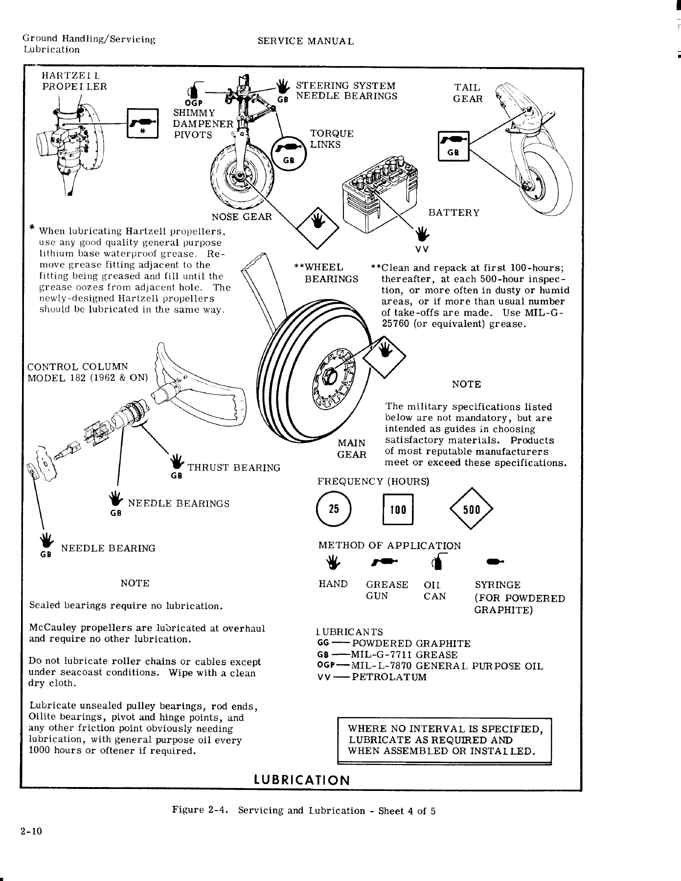
- Section 5 — Landing Gear: Spring-steel main gear leaves, U-bolt and wedge attachments, step bracket Conley-Weld bonding, Cleveland and Goodyear wheels and brakes, tubeless tire needle inflation, crosswind gear hubs, steerable air-oil nose struts, shimmy dampeners, steering linkages, and tailwheel assemblies.
- Section 6 — Aileron Control System: Direct-cable routing, control column sprockets, push-pull tubes, bellcranks, hinge pins, cable tensiometer settings, and surface travel adjustment.
- Section 7 — Flap Control Systems: Manual flap levers, ratchet mechanisms, flap cable tensioning, tracks, rollers, and push-pull rods.
- Section 7A — Flap Control System (Electric): Electric drive motors, jackscrew transmissions, position transmitters, limit switch adjustments, and cockpit indicators.
- Section 8 — Elevator Control Systems: Control tee assemblies, downspring mechanisms, cable circuits, pulley brackets, bellcranks, travel stops, and trim interaction.
- Section 9 — Elevator Trim Tab Control Systems: Cabin trim actuators, pedestal control wheels, sprocket chains, trim cables, push-pull rods, and tab surface rigging.
- Section 10 — Rudder Control Systems: Pedal bars, cable routing, nosewheel steering bungees, bellcranks, travel stops, and rudder trim tab bungee controls.
- Section 11 — Stabilizer Control System: Cockpit jack-screw control mechanisms, dual actuator screws, chains, and cables for adjustable trim stabilizers on Models 180, 185, and early 182.
- Section 12 — Powerplant: Continental O-200, O-300, GO-300, and O-470 engine maintenance, shock mount replacement, starter levers, generator belts, Bendix-Scintilla and Slick magneto timing, carburetors, baffled cowlings, and exhaust mufflers.
- Section 12A — Model 185 Powerplant: Fuel-injected Continental IO-470-F engine servicing, fuel/air control unit screens, fuel distribution manifolds, injection lines, cowl flap rigging, and oil cooler lines.
- Section 13 — Fuel Systems: Gravity-feed and fuel injection supply systems, rubber fuel cells, rigid metal wing tanks, fuel selectors, strainer bowls, auxiliary electric fuel pumps, vapor return lines, and quantity transmitters.
- Section 14 — Propellers: Fixed-pitch metal propellers, Hartzell constant-speed propeller hub greasing, McCauley constant-speed units, and engine governor adjustments.
- Section 14A — Propellers (Model BHC-C2YF-1): Specialized two-blade constant-speed propeller maintenance and blade angle checks.
- Section 15 — Heating and Ventilating: Cabin exhaust muff heat muffs, defrosting ducts, cabin fresh air scoop valves, and distribution manifolds.
- Section 16 — Instruments and Instrument Systems: Pitot-static plumbing, leak rate testing, vacuum system regulators, oil separators, engine temperature and pressure gauges, compass compensation, and stall warning horns.
- Section 17 — Electrical Systems: DC power generation, 12-volt battery circuitry, external ground power receptacles, starter circuits, navigation and rotating beacon wiring, schematic wiring diagrams, and component symbols.
- Section 19 — Structural Repair: Sheet metal skin patches, 2024-T3/T4 skin panel replacement, flush rivet patterns, Hi-Shear rivet replacement, spar splices, control surface static balancing procedures, and Fiberglas/Royalite component repairs.
- Section 20 — Painting: Enmar 27H lacquer, Enmar 82A vinyl coatings, high-visibility markings, and wheel fairing finish restoration.
For the professional aircraft technician, certified A&P mechanic, or dedicated restorer, this publication delivers complete technical clarity. Rather than offering basic field maintenance summaries, the manual delivers exact factory dimensions, tolerances, step-by-step tear-down sequences, component rebuild limits, and rigorous inspection criteria required to keep these vintage single-engine Cessna aircraft in compliant airworthy condition.
Airframe Rigging, Flight Controls & Structural Balance
Proper flight control rigging is critical to the safe operation and cruising performance of all Cessna single-engine aircraft. The 1962 & Prior Cessna 100 Series 150 172 175 180 182 185 Service Manual outlines the precise surface travel specifications, stop screw adjustments, and cable tensiometer readings across all control surfaces. Flight technicians will find detailed procedures for correcting a ‘wing-heavy’ condition utilizing the eccentric wing adjustment bushings located at the front spar wing root attachments, allowing angle-of-attack tuning without altering factory fuselage geometry.
The manual provides explicit surface angular limits: the Model 150 utilizes 20° up and 15° down aileron travel, 39° flap deflection, 16° left and right rudder travel, and 25° up to 15° down elevator travel. On the larger Model 180, 182, and 185 aircraft, technicians are provided with full data for both fixed and adjustable horizontal stabilizers. On models equipped with an adjustable stabilizer for pitch trim, the text outlines the mechanical screwjack travel parameters (such as the 0°45′ up to 8°45′ down stabilizer travel on late 180, 182, and 185 airframes) and instructions for coordinating elevator travel with the stabilizer in the full down position.
In Section 19, the manual presents precise instructions for airframe structural repair, covering spar cap doublers, rib replacement, bulkhead repairs, and the application of skin repair materials. Crucially, the manual provides comprehensive static control surface balancing procedures. Whenever ailerons, elevators, or rudders undergo metal repairs or repainting, technicians can utilize the detailed balance scale charts, jig arrangements, and maximum allowable overbalance/underbalance inch-pound tolerances to eliminate high-speed flutter hazards.
Powerplant, Fuel Injection & Electrical Architecture
Powerplant maintenance instructions span the entire family of Continental aircraft engines installed across early Cessna production. Technicians will find complete service protocols for the four-cylinder Continental O-200-A (rated at 100 HP at 2750 RPM) in the Model 150, the six-cylinder Continental O-300-A, O-300-C, and O-300-D (145 HP at 2700 RPM) in the Model 172 and Skyhawk, and the geared GO-300 series (175 HP at 3200 crankshaft RPM) powering the 175 Skylark. For heavy hauling and backcountry utility, detailed sections cover the Continental O-470 series (225 to 230 HP) in the 180 and 182, as well as the fuel-injected IO-470-F (260 HP at 2625 RPM) featured in the Model 185 Skywagon.
Detailed instructions walk the mechanic through engine removal and replacement, shock mount elastomer inspection, starter drive alignment, generator brush wear limits, voltage regulator point adjustments, and starting vibrator servicing. Ignition system maintenance includes complete timing and overhaul steps for both Bendix-Scintilla and Slick magnetos, including internal E-gap timing, breaker point clearances, and spark plug maintenance. For fuel systems, the manual breaks down gravity-feed carburetor installations alongside the continuous-flow fuel injection architecture of the Model 185, covering fuel/air control unit screens, fuel manifold distributors, injection line purging, and fuel tank sump drain safetying.
IMAGES PREVIEW
Landing Gear Servicing, Wheel Alignment & Brake Overhaul
Landing gear reliability is paramount for commercial training, cross-country flight, and rough-field operations. This manual provides extensive coverage of Cessna’s iconic chrome-vanadium spring-steel main landing gear legs. It covers the multiple fuselage attachment methods utilized across production changes, including U-bolts, wedge-and-shim retainers, and forged channel clamps. Mechanics will find exact instructions for replacing landing gear step brackets using Conley-Weld structural adhesive, complete with surface preparation, mix ratios, clamping pressures, and curing heat cycles.
To prevent premature tire wear and erratic taxi handling, the manual provides complete camber and toe-in alignment specifications for each individual airframe model, accompanied by engineering shim selection charts for correcting gear spring splay. Detailed servicing and overhaul procedures cover both Goodyear and Cleveland main wheels, tube-type and tubeless tires, internal gear-tooth drive discs, floating calipers, and brake master cylinder bleeding. Tricycle gear models receive dedicated instructions for servicing air-oil oleo nose struts, including fluid replenishment with MIL-H-5606 hydraulic oil, inflation pressures (ranging from 20 psi on the 150 to 50 psi on later 182 models), torque link bushing replacement, and shimmy dampener servicing.
Essential Shop Documentation & Instant Digital Access
Having immediate access to the 1962 & Prior Cessna 100 Series 150 172 175 180 182 185 Service Manual ensures your hangar, maintenance shop, or personal flight bag is equipped with authentic Cessna factory specifications. Following exact torque values (from AN fine thread nuts to coarse structural bolts), correct hydraulic fluids, approved lubricants, and certified cable rigging procedures protects aircraft value, ensures logbook sign-off compliance, and guarantees flight safety.
Delivered as an instant high-resolution digital PDF download immediately upon checkout, there are no shipping fees or transit delays. The file is fully compatible across all devices—including Windows PCs, Mac laptops, iPads, tablets, and smartphones. Technicians can zoom into high-resolution wiring schematics and exploded assembly drawings directly at the workbench, or print out clean, individual procedural sections and inspection checklists to take straight out to the aircraft tie-down or hangar floor.
Reviews
There are no reviews yet.