★ TRUSTED BY 321,897+ PROFESSIONALS WORLDWIDE
🏢
Trusted Business
Verified & Licensed
🛡️
Virus Free Files
100% Safe Downloads
🔒
Secure Payment
SSL Protected
Instant Delivery
Available Immediately
Sale!

1974-1985 Cessna 180 & 185 Series Illustrated Parts Catalog (P699-12)

Original price was: $39.95.Current price is: $24.95.

Comprehensive 650-page factory illustrated parts catalog for the 1974 through 1985 Cessna 180 and 185 Series aircraft, including Skywagon, Skywagon II, and AGcarryall models. Features complete exploded parts diagrams, numerical and alphabetical indexes, factory part numbers, hardware specifications, and serial number breakdowns.

Instant PDF Download
Available immediately
💾
Save to Your Device
Download & keep forever
🛡️
Antivirus Scanned
100% virus-free
🌍
Trusted Worldwide
175,000+ customers

Description

The 1974-1985 Cessna 180 & 185 Series Illustrated Parts Catalog (P699-12) is the definitive master parts reference manual published by Cessna Aircraft Company. This publication is a complete reissue that supersedes and replaces all previous 180 and 185 Series parts catalogs dated from 1 November 1973 through 1 March 1985, as well as Temporary Revision 1 dated 1 March 1995. Spanning 650 pages of detailed engineering illustrations, exploded assembly schematics, and comprehensive tabular parts breakdowns, this catalog provides an indispensable, authoritative roadmap for identifying, sourcing, and verifying every replaceable part, bracket, skin, fastener, and assembly on late-model Cessna utility taildraggers.

File Details

  • Manual Type: Illustrated Parts Catalog (IPC)
  • Aircraft Brand: Cessna Aircraft Company (A Textron Company)
  • Models Covered: Cessna 180J, 180K, Skywagon 180, 180 Skywagon II, A185F, Skywagon 185, 185 Skywagon II, and A185F AGcarryall
  • Model Coverage Years: 1974 thru 1985
  • Publication / Document Number: P699-12 (RGI-50-1/01)
  • Reissue Date: 3 February 1997
  • Total Page Count: 650 pages
  • Language: English
  • File Format: Adobe PDF

Comprehensive Model & Serial Number Coverage

This 1974-1985 Cessna 180 & 185 Series Illustrated Parts Catalog covers the complete production span of late-model Cessna 180 and 185 utility and agricultural aircraft. Exact serial group listings ensure you identify the precise parts configured for your airframe:

  • Cessna 180J Skywagon: Model Year 1974 (Serial 18052385 thru 18052500); Model Year 1975 (Serial 18052501 thru 18052620); Model Year 1976 (Serial 18052621 thru 18052770)
  • Cessna 180K Skywagon / Skywagon II: Model Year 1977 (Serial 18052771 thru 18052905); Model Year 1978 (Serial 18052906 thru 18053000); Model Year 1979 (Serial 18053001 thru 18053115); Model Year 1980 (Serial 18053116 thru 18053167); Model Year 1981 (Serial 18053168 thru 18053203)
  • Cessna A185F Skywagon / Skywagon II: Model Year 1974 (Serial 18502311 thru 18502565); Model Year 1975 (Serial 18502566 thru 18502838); Model Year 1976 (Serial 18502839 thru 18503153); Model Year 1977 (Serial 18503154 thru 18503458); Model Year 1978 (Serial 18503459 thru 18503683); Model Year 1979 (Serial 18503684 thru 18503938); Model Year 1980 (Serial 18503939 thru 18504138); Model Year 1981 (Serial 18504139 thru 18504328); Model Year 1982 (Serial 18504329 thru 18504394); Model Year 1983 (Serial 18504395 thru 18504415); Model Year 1984 (Serial 18504416 thru 18504424); Model Year 1985 (Serial 18504425 and on)
  • Cessna A185F AGcarryall: Production Years 1974 thru 1979 (Serial 18502311 thru 18503938)

Catalog Organization & Parts System Conventions

Cessna structured this parts publication using a standardized index and coding hierarchy designed for rapid navigation and procurement accuracy. The front matter contains an extensive Alphabetical Index cross-referencing components to individual figure numbers, while the rear features a comprehensive Numerical Index listing every part number and figure location in the publication. Key conventions integrated throughout the listings include:

  • Standard Parts System: Standard hardware parts incorporate Cessna standard prefixes (designated with prefix ‘S’), alongside standard military and aerospace standard hardware identified by AN, MS, and NAS designations.
  • Usable On Codes: A letter coding system located in the far-right column of each parts list table clearly defines the specific serial blocks and airframe configurations applicable to each part variant.
  • Indention Hierarchy: Component relationships are indicated by the degree of column indention, clearly differentiating major parent assemblies, lower subassemblies, detail parts, and attaching hardware.
  • Interchangeable Parts ‘WEU’ Notation: When later-design components fully supersede earlier iterations, the catalog lists both part numbers accompanied by the ‘When Exhausted Use’ (WEU) notation, streamlining distributor stocking and maintenance compliance.
  • Finish and Trim Coding: Comprehensive color charts and trim plate decoding matrices covering 1974 through 1985 paint formulations, urethane coatings, vinyls, leathers, and interior plastic components.

IMAGES PREVIEW

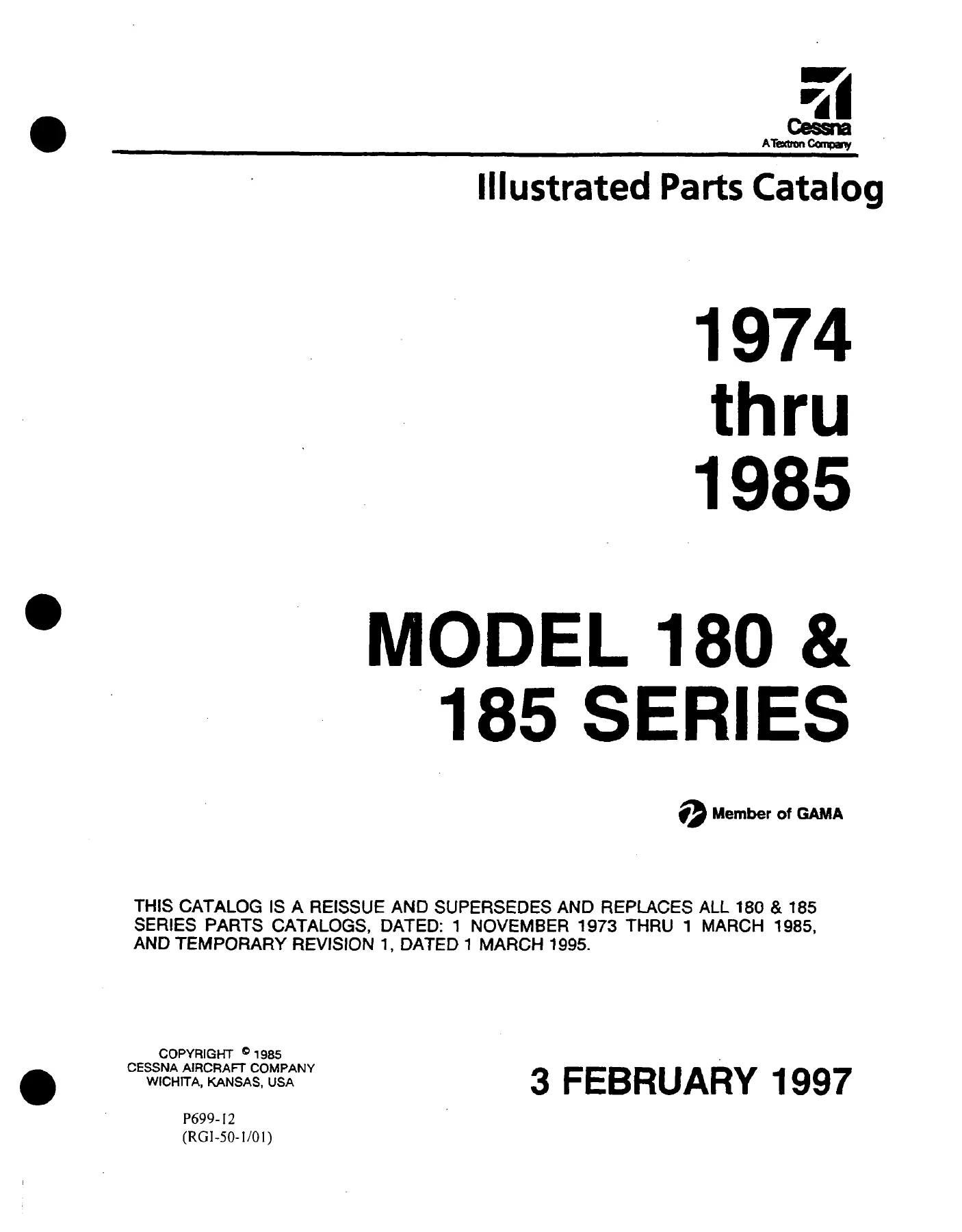
1974-1985 Cessna 180 & 185 Series Illustrated Parts Catalog (P699-12) — PDF page 1 preview
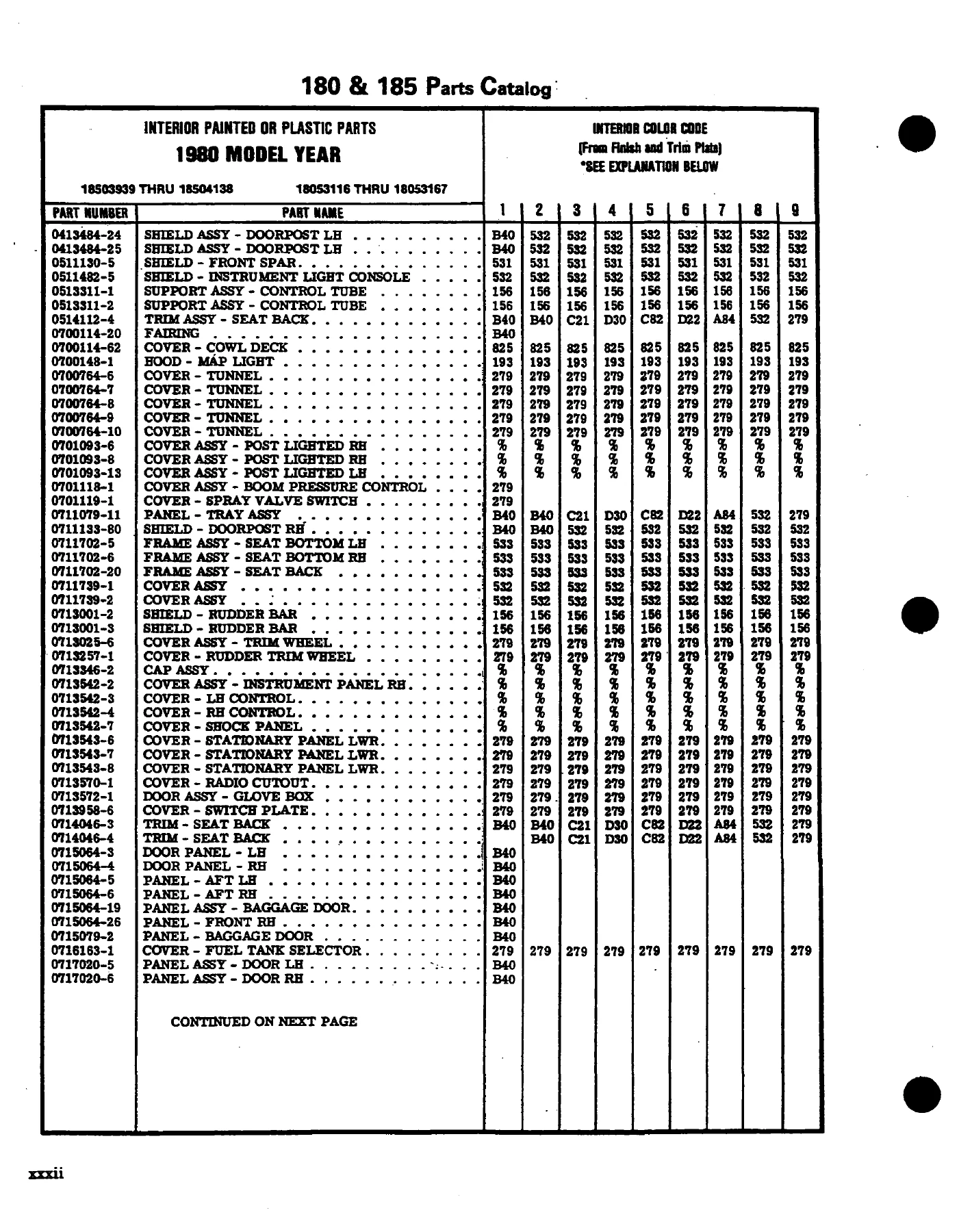
1974-1985 Cessna 180 & 185 Series Illustrated Parts Catalog (P699-12) — PDF page 32 preview
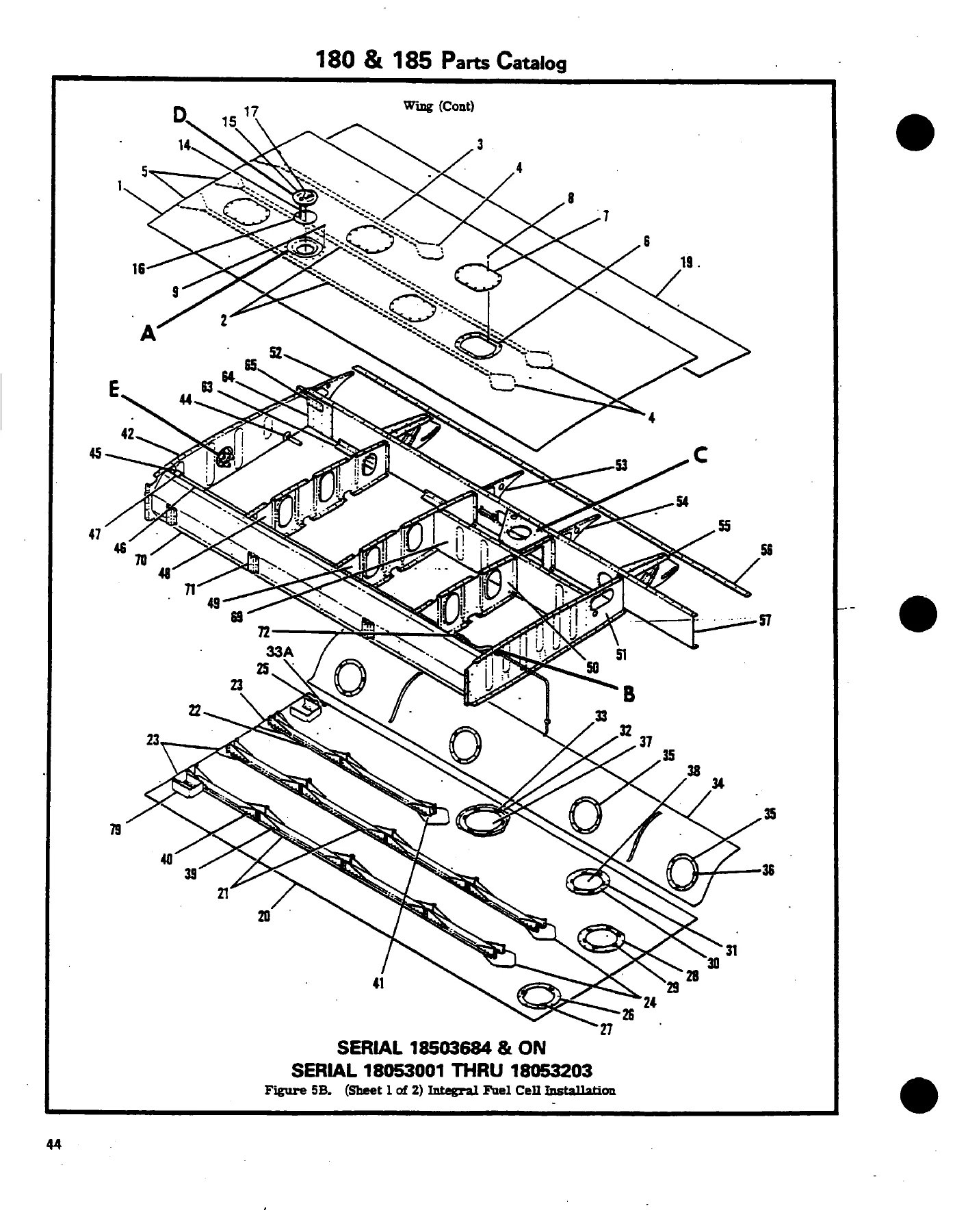
1974-1985 Cessna 180 & 185 Series Illustrated Parts Catalog (P699-12) — PDF page 92 preview

Chapters Covered

  • General Information & Bulk Items: Publication usage instructions, Finish & Trim plate interpretation, annual paint code charts (1974-1985), miscellaneous bulk items, extruded seals, adhesives, hose stock, ducting, and registration stencil/decal markings (Figures 1 thru 1A).
  • Placards & Exterior Markings: Detailed placard arrays, interior operation decals, limitations, fuel management markings, instrument panel legends, and exterior designation emblems (Figures 2 thru 3A).
  • Wing Group: Complete wing assembly layouts, bladder fuel tank wing structure, integral fuel cell wing structure, leading edge assemblies, front/rear spar assemblies, skin and stringer installations, and wing strut attachments (Figures 4 thru 8A).
  • Fuel Storage & Venting: Bladder fuel tank installations, integral wet-wing fuel cell installations, fuel tank drain valves, quick drains, and venting networks (Figures 9 thru 10).
  • Control Surfaces: Aileron assembly and push-pull rod installations, flap assembly and flap track roller installations, balance weights, and trailing edge ribs (Figures 11 thru 12).
  • Empennage Structures: Vertical fin and dorsal fin installations, horizontal stabilizer assemblies, elevators with balance weights, and rudder assemblies for standard taildraggers and floatplanes (Figures 14 thru 18).
  • Fuselage Structures: Complete fuselage assemblies, front and center section framing, cabin roof skin, skylight framing, cabin floorboards, bulkhead stations (Sta. 44.00, Sta. 50.00, Sta. 65.33, Sta. 79.35, Sta. 90.00, Sta. 108.00, Sta. 140.00, Sta. 172.00, Sta. 209.00), baggage shelf structures, and tailcone installations (Figures 19 thru 29A).
  • Alighting Gear & Brakes: Spring-steel main landing gear legs, axles, wheel and brake assemblies (Cleveland and McCauley installations), parking brake controls, master cylinders, brake lines, and fairings (Figures 34 thru 36A).
  • Tailwheel Assemblies: Steerable non-locking tailwheel assemblies, steerable manual-locking tailwheel installations, lock cables, tailwheel springs, forks, hubs, and tires (Figures 37 thru 39A).
  • Doors & Windows: Cabin door assemblies, door latches, removable hinge pins, domed window assemblies, and baggage door installations (Figures 40 thru 44A).
  • Interior & Furnishings: Cabin door upholstery, headliners, sidewall trim panels, carpet installations, standard seats, infinitely adjustable front seats, middle bench seats, divided middle seats, and stowable rear seats (Figures 45 thru 54C).
  • Flight Control Systems: Control yokes, control wheels, aileron cable routing, flap control lever and ratchet systems, elevator control cables, rudder pedal linkages, rudder trim controls, and stabilizer jackscrew trim controls (Figures 81 thru 94).
  • Pitot-Static & Instruments: Pitot system piping, alternate static source valves, stall warning systems, instrument panel structural shock panels, post-lighted panel overlays, switch and circuit breaker consoles, and engine instrument clusters (Figures 55 thru 57C, 95 thru 97).
  • Powerplant & Propeller: Continental engine mounts, shock isolators, engine baffles, cowling assemblies, cowl flaps and linkages, oil cooler installations, exhaust manifolds and mufflers, two-bladed and three-bladed McCauley propeller hubs, spinners, and governors (Figures 61 thru 78).
  • Fuel Management & Plumbing: Fuel selector valves, fuel strainer assemblies, engine-driven and auxiliary fuel pumps, fuel primers, and vapor separator tanks (Figures 98 thru 105).
  • Special Mission & Utility Systems: Agricultural equipment, chemical spray tanks, boom pressure controls, dump valves, wire cutters, cargo pack installations, and floatplane structural bracing (Figures 117 thru 124A).

Together, these sections equip maintenance personnel, aircraft mechanics, parts managers, and vintage aircraft restorers with a complete, granular reference to every nut, bolt, washer, rivet, skin panel, and hydraulic line installed across the 1974-1985 Cessna 180 and 185 fleet.

Complete PDF Bookmark Tree

Complete Bookmarks

The complete bookmarks in the “1974-1985 Cessna 180 & 185 Series Illustrated Parts Catalog (P699-12)” are as follows:

P699-12 – MODELS 180 AND 185 SERIES (1974 THRU 1985)p. 1
LIST OF EFFECTIVE PAGESp. 2
INTRODUCTIONp. 3
AEROFICHEp. 3
STANDARD PARTSp. 3
USABLE ON CODESp. 3
SYMBOLS & PART NUMBER TERMSp. 4
GROUP ASSEMBLY PARTS LIST ARRANGEMENTp. 4
ACCESSORY KITSp. 5
BULK ITEMSp. 5
HOW TO ORDERp. 5
SERIAL, COLOR, & CORROSION PROOFINGp. 5
DISTRIBUTOR ORDERSp. 5
RETAIL ORDERSp. 5
ADDITIONAL PUBLICATIONSp. 5
IMPORTANT INFORMATION CONCERNING KEEPING CESSNA PUBLICATIONS CURRENTp. 6
PAINT & UPHOLSTERY COMBINATIONSp. 8
FINISH & TRIM PLATE 1974 THRU 1977p. 8
FINISH & TRIM PLATE 1978 THRU 1980p. 9
FINISH & TRIM PLATE 1981p. 10
PAINT CODE CHARTp. 11
PAINT CODE CHART 1974p. 11
PAINT CODE CHART 1976p. 13
PAINT CODE CHART 1978p. 15
PAINT CODE CHART 1980p. 17
PAINT CODE CHART 1982p. 19
PAINT CODE CHART 1984p. 21
UPHOLSTERY & INTERIOR TRIMp. 23
UPHOLSTERED PARTS – HOW TO ORDERp. 24
INTERIOR PAINTED OR PLASTIC PARTS HOW TO ORDERp. 25
INTERIOR PAINTED OR PLASTIC PARTS 1975 MODEL YEARp. 27
INTERIOR PAINTED OR PLASTIC PARTS 1976 MODEL YEARp. 28
INTERIOR PAINTED OR PLASTIC PARTS 1977 MODEL YEARp. 29
INTERIOR PAINTED OR PLASTIC PARTS 1978 MODEL YEARp. 30
INTERIOR PAINTED OR PLASTIC PARTS 1979 MODEL YEARp. 31
INTERIOR PAINTED OR PLASTIC PARTS 1980 MODEL YEARp. 32
ALPHABETICAL INDEXp. 34
PARTS LISTINGp. 52
BULK ITEMSp. 53
FIGURE 1. MISCELLANEOUS BULK ITEMSp. 55
REGISTRATION MARKINGSp. 57
FIGURE 1A. (SHEET 1 OF 3) REGISTRATION MARKINGSp. 58
FIGURE 1A. (SHEET 2 OF 3) REGISTRATION MARKINGSp. 59
FIGURE 1A. (SHEET 3 OF 3) REGISTRATION MARKINGSp. 60
PLACARDSp. 62
FIGURE 2. (SHEET 1 OF 2) PLACARDS, NAMEPLATES, & EXTERIOR MARKINGSp. 61
FIGURE 2. (SHEET 2 OF 2) PLACARDS, NAMEPLATES, & EXTERIOR MARKINGSp. 63
FIGURE 2A. (SHEET 1 OF 2) PLACARDS, NAMEPLATES & EXTERIOR MARKINGSp. 65
FIGURE 2A. (SHEET 2 OF 2) PLACARDS, NAMEPLATES & EXTERIOR MARKINGSp. 67
FIGURE 2B. (SHEET 1 OF 2) PLACARDS, NANEPLATES & EXTERIOR MARKINGSp. 69
FIGURE 2B. (SHEET 2 OF 2) PLACARDS, NAMEPLATES & EXTERIOR MARKINGSp. 71
FIGURE 3. (SHEET 1 OF 2) PLACARDS, NAMEPLATES & EXTERIOR MARKINGSp. 73
FIGURE 3. (SHEET 2 OF 2) PLACARDS, NAMEPLATES & EXTERIOR MARKINGSp. 75
FIGURE 3A. (SHEET 1 OF 2) PLACARDS, NAMEPLATES & EXTERIOR MARKINGSp. 77
FIGURE 3A. (SHEET 2 OF 2) PLACARDS, NAMEPLATES & EXTERIOR MARKINGSp. 79
WINGSp. 82
FIGURE 4. WING ASSEMBLY COMPLETE – BLADDER FUEL TANKp. 81
FIGURE 4A. WING ASSEMBLY COMPLETE – INTERGRAL FUEL CELLp. 85
FIGURE 5. WING STRUCTURE ASSEMBLY – BLADDER FUEL TANKp. 88
FIGURE 5A. WING STRUCTURE ASSEMBLY – INTEGRAL FUEL CELLp. 90
FIGURE 5B. (SHEET 1 OF 2) INTEGRAL FUEL CELL INSTALLATIONp. 92
FIGURE 5B. (SHEET 2 OF 2) INTEGRAL FUEL CELL INSTALLATIONp. 93
FIGURE 6. WING LEADING EDGE ASSEMBLYp. 99
FIGURE 7. WING SPAR ASSEMBLIES – BLADDER FUEL TANKSp. 101
FIGURE 7A. WING SPAR ASSEMBLIES – INTEGRAL FUEL CELLSp. 104
FIGURE 8. SKINS & STRINGERS INSTALLATION – BLADDER FUEL TANKSp. 106
FIGURE 8A. SKINS & STRINGERS INSTALLATION – INTEGRAL FUEL CELLSp. 109
FIGURE 9. BLADDER FUEL TANK INSTALLATIONp. 112
FIGURE 10. FUEL TANK DRAIN VALVE INSTALLATIONp. 115
FIGURE 11. AILERON INSTALLATIONp. 117
FIGURE 12. FLAP INSTALLATIONp. 119
STRUTp. 122
FIGURE 13. STRUT INSTALLATIONp. 121
EMPENNAGEp. 124
FIGURE 14. FIN & DORSAL INSTALLATIONp. 123
FIGURE 15. FIN& DORSAL INSTALLATIONp. 125
FIGURE 16. STABILIZER INSTALLATIONp. 127
FIGURE 17. RUDDER INSTALLATIONp. 131
FIGURE 18. ELEVATOR INSTALLATIONp. 133
FUSELAGEp. 136
FIGURE 19. FUSELAGE ASSEMBLYp. 135
FIGURE 20. FUSELAGE FRONT & CENTER SECTIONp. 138
FIGURE 20A. (SHEET 1 OF 2) FUSELAGE FRONT & CENTER SECTIONp. 142
FIGURE 20A. (SHEET 2 OF 2) FUSELAGE FRONT & CENTER SECTIONp. 143
FIGURE 20B. SEAT BELT MOUNTING ASSEMBLYp. 148
FIGURE 21. REAR CABIN TOP SKIN ASSEMBLYp. 150
FIGURE 22. FUSELAGE CENTER SECTION FLOORBOARDS INSTALLATIONp. 152
FIGURE 22A. FUSELAGE CENTER SECTION FLOORBOARDS INSTALLATIONp. 154
FIGURE 23. FUSELAGE FRONT SECTION STRUCTURE ASSEMBLYp. 156
FIGURE 24. LANDING GEAR BULKHEAD ASSEMBLYp. 160
FIGURE 25. WINDSHIELD INSTALLATIONp. 163
FIGURE 26. FUSELAGE BULKHEAD ASSEMBLY STA. 65.33p. 164
FIGURE 27. FIREWALL ASSEMBLYp. 167
FIGURE 27A. FIREWALL ASSEMBLYp. 169
FIGURE 27B. FIREWALL ASSEMBLYp. 171
FIGURE 28. FIREWALL GROMMETS INSTALLATIONp. 174
FIGURE 29. FUSELAGE AFT SECTION ASSEMBLYp. 176
FIGURE 29A. FUSELAGE AFT SECTION ASSEMBLYp. 181
FIGURE 30. LITTER DOOR COMPONENT INSTALLATIONp. 185
FIGURE 31. BATTERY BOX ASSEMBLYp. 187
FIGURE 31A. BATTERY BOX INSTALLATIONp. 188
FIGURE 31B. MANIFOLD BATTERY SUPPORT INSTALLATIONp. 190
FIGURE 32. FUSELAGE TAILCONE ASSEMBLYp. 192
FIGURE 33. STINGER INSTALLATIONp. 194
ALIGHTING GEARp. 197
FIGURE 34. MAIN LANDING GEAR INSTALLATIONp. 196
FIGURE 35. MAIN GEAR WHEEL & BRAKE ASSEMBLIESp. 199
FIGURE 36. MAIN GEAR WHEEL & BRAKE ASSEMBLIESp. 201
FIGURE 36A. MAIN GEAR WHEEL & BRAKE INSTALLATIONp. 203
FIGURE 37. TAILWHEEL INSTALLATION – NON LOCKINGp. 205
FIGURE 37A. TAILWHEEL INSTALLATION – NON LOCKINGp. 207
FIGURE 38. TAILWHEEL & LOCK INSTALLATION – MANUALp. 209
FIGURE 38A TAILWHEEL & LOCK INSTALLATIONp. 212
FIGURE 39. TAILWHEEL ASSEMBLYp. 216
FIGURE 39A. TAILWHEEL & LOCK ASSEMBLYp. 218
DOOR & WINDOWp. 222
FIGURE 40. CABIN DOOR INSTALLATIONp. 221
FIGURE 41. CABIN DOOR INSTALLATION – LOWER WINDOWp. 225
FIGURE 42. DOMED WINDOW ASSEMBLYp. 228
FIGURE 43. CABIN DOOR LATCH ASSEMBLYp. 230
FIGURE 44. BAGGAGE DOOR INSTALLATIONp. 232
FIGURE 44A. BAGGAGE DOOR INSTALLATIONp. 234
UPHOLSTERYp. 237
FIGURE 45. CABIN DOORS UPHOLSTERY INSTALLATIONp. 236
FIGURE 46. CABIN TOP & FIREWALL UPHOLSTERY INSTALLATIONp. 238
FIGURE 47. CABIN SIDE PANELS & BAGGAGE COMPARTMENT UPHOLSTERY INSTALLATIONp. 240
FIGURE 48. FLOORBOARD UPHOLSTERY INSTALLATIONp. 245
FIGURE 48A. FLOORBOARD UPHOLSTERY INSTALLATIONp. 247
SEATSp. 250
FIGURE 49. FRONT SEAT INSTALLATIONp. 249
FIGURE 49A. FRONT SEAT INSTALLATIONp. 253
FIGURE 49B. FRONT SEAT INSTALLATIONp. 255
FIGURE 49C. FRONT SEAT INSTALLATIONp. 259
FIGURE 50. INFINITELY ADJUSTABLE FRONT SEAT INSTALLATIONp. 261
FIGURE 50A. INFINITELY ADJUSTABLE FRONT SEAT INSTALLATIONp. 265
FIGURE 50B. INFINITELY ADJUSTABLE FRONT SEAT INSTALLATIONp. 269
FIGURE 51. REAR SEAT INSTALLATIONp. 274
FIGURE 52. CHILD SEAT INSTALLATIONp. 277
FIGURE 53. STOWABLE REAR SEATS INSTALLATIONp. 279
FIGURE 54. DIVIDED MIDDLE SEAT INSTALLATIONp. 281
FIGURE 54A. MIDDLE BENCH SEAT INSTALLATIONp. 285
FIGURE 54B. MIDDLE BENCH SEAT INSTALLATIONp. 289
FIGURE 54C. AFT BENCH SEAT INSTALLATIONp. 291
PANEL EQUIPMENTp. 295
FIGURE 55. INSTRUMENT PANEL EQUIPMENT INSTALLATIONp. 294
FIGURE 55A. INSTRUMENT PANEL EQUIPMENT INSTALLATIONp. 301
FIGURE 55B. INSTRUMENT PANEL EQUIPMENT INSTALLATIONp. 309
FIGURE 55C. INSTRUMENT PANEL EQUIPMENT INSTALLATIONp. 318
FIGURE 56. SWITCH & CIRCUIT BREAKER INSTALLATIONp. 323
FIGURE 56A. SWITCH & CIRCUIT BREAKER INSTALLATIONp. 325
FIGURE 57. POST LIGHTED INSTRUMENT PANEL INSTALLATIONp. 327
FIGURE 57A. POST LIGHTED INSTRUMENT PANEL INSTALLATIONp. 329
FIGURE 57B. POST LIGHTED INSTRUMENT PANEL INSTALLATIONp. 331
FIGURE 57C. POST LIGHTED INSTRUMENT PANEL INSTALLATIONp. 334
FIGURE 58. GLOVE BOX INSTALLATIONp. 336
FIGURE 58A. GLOVE BOX INSTALLATIONp. 337
FUSELAGE EQUIPMENTp. 340
FIGURE 59. FUSELAGE EQUIPMENT INSTALLATIONp. 339
FIGURE 59A. SHOULDER HARNESS & FRONT SEAT BELT INSTALLATIONp. 343
FIGURE 59B. INERTIA REEL INSTALLATIONp. 346
FIGURE 60. AUXILIARY REFUELING EQUIPMENT INSTALLATIONp. 348
FIGURE 60A. FIRE EXTINGUISHER INSTALLATIONp. 350
PROPELLERp. 353
FIGURE 61. PROPELLER & SPINNER INSTALLATION – TWO BLADEDp. 352
FIGURE 62. PROPELLER ASSEMBLYp. 354
FIGURE 63. PROPELLER ASSEMBLYp. 358
FIGURE 63A. PROPELLER & SPINNER INSTALLATION – THREE BLADEDp. 360
COWLINGp. 363
FIGURE 64. ENGINE COWL INSTALLATIONp. 362
COWL FLAP CONTROLp. 367
FIGURE 65. COWL FLAP CONTROLS SYSTEMp. 366
FIGURE 65A. COWL FLAP CONTROL SYSTEMp. 368
WINTERIZATIONp. 370
FIGURE 66. WINTERIZATION EQUIPMENT INSTALLATIONp. 370
ENGINEp. 371
FIGURE 67. (SHEET 1 OF 2) ENGINE INSTALLATIONp. 372
FIGURE 67. (SHEET 2 OF 2) ENGINE INSTALLATIONp. 373
FIGURE 68. (SHEET 1 OF 2) ENGINE INSTALLATIONp. 377
FIGURE 68. (SHEET 2 OF 2) ENGINE INSTALLATIONp. 378
FIGURE 69. (SHEET 1 OF 2) ENGINE ASSEMBLYp. 381
FIGURE 69. (SHEET 2 OF 2) ENGINE ASSEMBLYp. 382
FIGURE 71. ENGINE ASSEMBLYp. 387
FIGURE 73. NON CONGEALING OIL COOLER INSTALLATIONp. 392
FIGURE 74. PROPELLER GOVERNOR ASSEMBLYp. 394
FIGURE 75. PROPELLER GOVERNOR ASSEMBLYp. 396
FIGURE 76. EXHAUST SYSTEM ASSEMBLYp. 398
FIGURE 77. ENGINE BAFFLES INSTALLATIONp. 400
FIGURE 78. ENGINE BAFFLES INSTALLATIONp. 404
VENTILATION SYSTEMp. 407
FIGURE 79. CABLE VENTILATION SYSTEMp. 406
HEATING SYSTEMp. 410
FIGURE 80. CABIN HEATING SYSTEMp. 409
BRAKE SYSTEMp. 412
FIGURE 81. BRAKE SYSTEMp. 413
RUDDER PEDALSp. 416
FIGURE 82. RUDDER & BRAKE PEDAL INSTALLATIONp. 415
FIGURE 83. RUDDER & BRAKE PEDAL INSTALLATIONp. 419
MASTER CYCLINDERp. 421
FIGURE 84. MASTER BRAKE CYLINDER ASSEMBLYp. 421
FIGURE 85. MASTER BRAKE CYLINDER ASSEMBLYp. 422
FLIGHT CONTROLSp. 423
FIGURE 86. CONTROL YOKE INSTALLATIONp. 424
FIGURE 87. CONTROL WHEEL & SWITCHES INSTALLATIONp. 426
FIGURE 88. AILERON CONTROL SYSTEMp. 428
FIGURE 88A. AILERON CONTROL SYSTEMp. 431
FIGURE 89. FLAP CONTROL SYSTEMp. 435
FIGURE 90. ELEVATOR CONTROL SYSTEMp. 437
FIGURE 91. RUDDER CONTROL SYSTEMp. 439
FIGURE 92. RUDDER TRIM INSTALLATIONp. 441
FIGURE 93. STABILIZER TRIM CONTROL SYSTEMp. 444
FIGURE 94. STABILIZER TRIM WHEEL INSTALLATIONp. 446
PITOT SYSTEMp. 449
FIGURE 95. PITOT SYSTEMp. 448
FIGURE 95A. PITOT SYSTEMp. 452
FIGURE 96. ALTERNATE STATIC SOURCE INSTALLATIONp. 454
FIGURE 96A. ALTERNATE STATIC SOURCE INSTALLATIONp. 456
FIGURE 96B. ENCODING ALTIMETER INSTALLATIONp. 458
STALL WARNINGp. 460
FIGURE 97. STALL WARNING HORN INSTALLATIONp. 460
FUEL SYSTEMp. 461
FIGURE 98. FUEL SYSTEMp. 462
FIGURE 99. FUEL SYSTEM – SELECTABLE TANKp. 464
FIGURE 99A. FUEL SYSTEM – SELECTABLE TANKp. 467
FIGURE 99B. FUEL SYSTEMp. 471
FIGURE 99C. (SHEET 1 OF 2) FUEL SYSTEMp. 474
FIGURE 99C. (SHEET 2 OF 2) FUEL SYSTEMp. 475
FIGURE 100. FUEL SYSTEMp. 480
FIGURE 100A. FUEL SYSTEMp. 482
FIGURE 101. AUXILIARY FUEL PUMP & STRAINER INSTALLATIONp. 485
FIGURE 102. FUEL STRAINER & DRAIN CONTROL INSTALLATIONp. 487
FIGURE 102A. FUEL SHUT OFF VALVEp. 489
FIGURE 103. FUEL SELECTOR VALVE ASSEMBLYp. 490
FIGURE 103A. FUEL SELECTOR VALVE ASSEMBLYp. 491
FIGURE 104. FUEL PRIMER SYSTEMp. 493
FIGURE 105. FUEL PRIMER SYSTEMp. 495
OIL SYSTEMp. 498
FIGURE 106. OIL SYSTEMp. 497
FIGURE 106A. OIL SYSTEMp. 499
VACCUM SYSTEMp. 502
FIGURE 107. VACUUM SYSTEMp. 501
FIGURE 107A. VACUUM SYSTEMp. 505
FIGURE 107B. VACUUM SYSTEMp. 507
FIGURE 107C. VACUUM SYSTEMp. 511
FIGURE 107D. VACUUM PUMP INSTALLATION – ELECTRIC STANDBYp. 513
OXYGEN SYSTEMp. 516
FIGURE 108. OXYGEN SYSTEMp. 515
FIGURE 108A. OXYGEN SYSTEMp. 519
ELECTRICAL EQUIPMENTp. 522
FIGURE 109. ELECTRICAL EQUIPMENT INSTALLATIONp. 523
FIGURE 109A. ELECTRICAL EQUIPMENT INSTALLATIONp. 525
FIGURE 109B. ELECTRICAL EQUIPMENT INSTALLATIONp. 529
FIGURE 110. CABIN LIGHTS & COURTESY LIGHT INSTALLATIONp. 532
FIGURE 111. MAP LIGHT INSTALLATIONp. 534
FIGURE 112. SHOCK MOUNTED ALTERNATOR INSTALLATIONp. 536
FIGURE 112A. ALTERNATOR INSTALLATIONp. 538
FIGURE 113. FLASHING BEACON INSTALLATIONp. 540
FIGURE 114. GROUND SERVICE PLUG INSTALLATION – LANDPLANEp. 542
FIGURE 115. GROUND SERVICE PLUG INSTALLATIONp. 543
FIGURE 116. LANDING LIGHT INSTALLATION – COWLp. 545
FIGURE 116A. MAP LIGHT & MIKE SWITCH INSTALLATIONp. 547
FIGURE 116B. MAP LIGHT & MIKE SWITCH INSTALLATIONp. 549
FIGURE 116C. COPILOTS INTERCOM MIKE SWITCH INSTALLATIONp. 551
FLOATPLANEp. 554
FIGURE 117. FLOATPLANE FITTINGS INSTALLATIONp. 553
FIGURE 118. FLOTPLANE & SKI PLANE COMPONENTSp. 557
FIGURE 118A. RUDDER RETURN INSTALLATIONp. 559
CARGO PACKp. 563
FIGURE 119. CARGO PACK INSTALLATIONp. 562
STRETCHERp. 565
FIGURE 120. STRETCHER INSTALLATIONp. 565
CAMERAp. 567
FIGURE 121. CENTER LINE CAMERA PROVISIONSp. 566
AGRICULTURAL DISPERSAL SYSTEMp. 571
FIGURE 122. WIRE CUTTER & CABLE DEFLECTOR INSTALLATIONp. 570
FIGURE 123. COWL FLAPS EXTENSION INSTALLATION – AGCARRYALLp. 573
FIGURE 124. SORENSEN SPRAY SYSTEMp. 575
FIGURE 124A. SORENSEN SPRAY SYSTEMp. 577
FIGURE 125. CONTROL BOX INSTALLATIONp. 579
FIGURE 126. CONTROLS AND CLAMPING INSTALLATIONp. 581
FIGURE 126A. (SHEET 1 OF 2) CONTROLS & CLAMPING INSTALLATIONp. 584
FIGURE 126A. (SHEET 2 OF 2) CONTROLS & CLAMPING INSTALLATIONp. 585
FIGURE 127. FAN BRAKE CONTROL INSTALLATIONp. 588
FIGURE 128. EMERGENCY TANK RELEASE AND BOOM HANGER DETAILSp. 590
FIGURE 129. PUMP, STRAINER AND VALVE INSTALLATIONp. 592
NUMERICAL INDEXp. 594

Key Structural & Engineering Systems

Working with the Cessna 180 & 185 Series Parts Catalog provides unprecedented clarity into the evolution of Cessna high-wing utility aircraft over twelve vital production years. The manual documents crucial mid-production transitions, including the evolution from rubber bladder fuel tanks to high-capacity integral wet-wing fuel bays introduced in the late 1970s. Every associated fuel sender, access panel doubler, finger strainer, and vent line is cataloged with exact serial breakpoints.

For landing gear and brake servicing, this manual offers complete pictorial breakdowns of standard heavy-duty spring steel gear legs, seaplane reinforcement bulkheads, and the interchangeability between early Cleveland brake systems and later McCauley assemblies. It details tailwheel components ranging from standard leaf springs and steering chains to heavy-duty locking tailwheel mechanisms designed for rugged backcountry operations. Furthermore, agricultural operators and bush pilots will find dedicated figures for AGcarryall spray booms, hopper gate dump valves, and external belly cargo packs.

Essential Parts Reference & Instant Delivery

Maintaining airworthiness and regulatory compliance on high-performance utility taildraggers requires absolute precision in replacement part verification. Whether you are conducting an annual inspection on a 1976 Cessna 180J, restoring an A185F Skywagon floatplane, or overhauling flight control cables and pulleys, the 1974-1985 Cessna 180 & 185 Series Illustrated Parts Catalog (P699-12) ensures you never order the wrong dash number, bracket, or fastener. Having exact Cessna part numbers and military standard hardware codes eliminates guesswork, prevents costly shipping returns, and reduces maintenance downtime.

This manual is provided as an immediate digital PDF download upon completion of payment. There are no shipping delays or physical book handling fees. The PDF file is fully accessible on desktop computers, workshop laptops, tablets, and smartphones, and can be printed in whole or by individual chapter for convenient use at the workbench or inside the hangar.
Reviews

There are no reviews yet.

Be the first to review “1974-1985 Cessna 180 & 185 Series Illustrated Parts Catalog (P699-12)”

What Our Customers Say

★★★★★ Live reviews from customers
Loading customer reviews...
0
    0
    Your Cart
    Your cart is emptyReturn to Shop
    🛒
    Recently Purchased
    🕒 verified order