★ TRUSTED BY 321,897+ PROFESSIONALS WORLDWIDE
🏢
Trusted Business
Verified & Licensed
🛡️
Virus Free Files
100% Safe Downloads
🔒
Secure Payment
SSL Protected
Instant Delivery
Available Immediately
Sale!

Piper Aztec PA-23-250 & Apache PA-23-235 Illustrated Parts Catalog

Original price was: $39.95.Current price is: $24.95.

Comprehensive factory illustrated parts catalog for the Piper PA-23-250 Aztec and PA-23-235 Apache series, covering airframe components, landing gear, control linkages, instrumentation, and systems with exploded drawings, part numbers, and serial applicability.

Instant PDF Download
Available immediately
💾
Save to Your Device
Download & keep forever
🛡️
Antivirus Scanned
100% virus-free
🌍
Trusted Worldwide
175,000+ customers

Description

Complete Factory Illustrated Parts Breakdown for Piper PA-23 Aircraft

The Piper Aztec PA-23-250 & Apache PA-23-235 Illustrated Parts Catalog provides airframe and powerplant mechanics, restoration specialists, and aircraft owners with an exhaustive visual reference and part-number identification source for Piper PA-23 series twin-engine aircraft. Published under Piper Aircraft Corporation publication number 753 522 and revised through July 1984, this catalog delivers complete exploded-view diagrams, part nomenclatures, sub-assembly indention structures, quantities required per assembly, and exact serial-number applicability across the production run of both the PA-23-235 Apache and all six-place PA-23-250 Aztec variants.

File Details

  • Manual Type: Illustrated Parts Catalog
  • Brand: Piper Aircraft Corporation
  • Applicable Models:
    • PA-23-235 Apache
    • PA-23-250 Aztec
    • PA-23-250 (Six Place) Aztec (Models B, C, D, E, and F)
  • Publication Part Number: 753 522 (PR840712)
  • Original Issue Date: August 15, 1972
  • Revision Date: Revised July 1984
  • Language: English
  • Page Count: 684 pages
  • File Format: Portable Document Format (PDF)

Serial Number & Model Applicability

This Piper Aztec PA-23-250 & Apache PA-23-235 Illustrated Parts Catalog contains precise serial-effectivity listings essential for locating the correct original equipment parts, interchangeable revisions, and optional equipment installations across the following production series:

  • 1960 Aztec PA-23-250: Serial numbers 27-1 through 27-366 inclusive
  • 1961 Aztec PA-23-250: Serial numbers 27-367 through 27-504 inclusive
  • Apache PA-23-235: Serial numbers 27-505 through 27-622 inclusive
  • Aztec PA-23-250 (Six Place) Model B: Serial numbers 27-2000 through 27-2504 inclusive
  • Aztec PA-23-250 (Six Place) Model C: Serial numbers 27-2505 through 27-3836 inclusive, and 27-3838 through 27-3943 inclusive
  • Aztec PA-23-250 (Six Place) Model D: Serial numbers 27-3837, 27-3944 through 27-4425 inclusive, and 27-4427 through 27-4573 inclusive
  • Aztec PA-23-250 (Six Place) Model E: Serial numbers 27-4426, 27-4574 through 27-7554168 inclusive
  • Aztec PA-23-250 (Six Place) Model F: Serial numbers 27-7654001 and up

Parts Catalog Organization & Code Structure

Every group in the Piper Aztec PA-23-250 & Apache PA-23-235 Illustrated Parts Catalog is structured to ensure positive, error-free identification of replacement components. Listings are organized across six functional columns:

  • Figure and Index Number: Cross-references each listed item directly to its corresponding detailed engineering illustration.
  • Part Number: Shows the exact Piper part number required for requisitions and ordering.
  • Code: Identifies specialized notes, optional equipment conditions, voltage configurations (14-volt or 28-volt), and specific airframe modifications.
  • Nomenclature: Displays the approved part title, with indentation levels using asterisks to illustrate parent-assembly and sub-component relationships.
  • No. Req.: Indicates the total quantity utilized per installation or within that specific sub-assembly.
  • Serial Numbers Affected: Pinpoints the exact airframe serial boundaries for part changes, service kit installations, and factory improvements.
  • Attaching Parts: Standard AN and MS commercial hardware specifications (bolts, washers, nuts, and clevis pins) are itemized directly following the main assemblies they secure.

Chapters Covered

  • Section I — Wing Group
    • Wing Installation
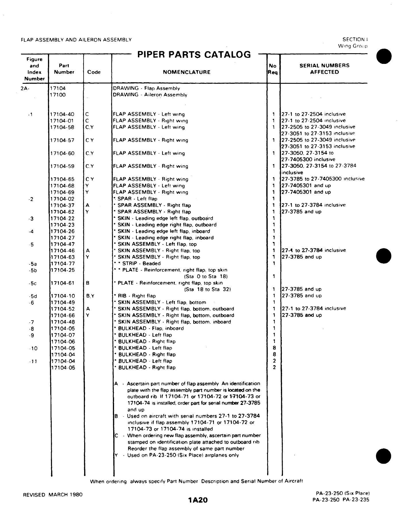
    • Flap Assembly and Aileron Assembly
    • Wing and Wing Tip Construction
    • Wing and Wing Tip Skin

    Complete PDF Bookmark Tree

    Complete Bookmarks

    The complete bookmarks in the “Piper Aztec PA-23-250 & Apache PA-23-235 Illustrated Parts Catalog” are as follows:

    753-522 – AZTEC PARTS CATALOG – PA-23-235 APACHE, PA-250 AZTEC, PA-23-250 (SIX PLACE) AZTECp. 1
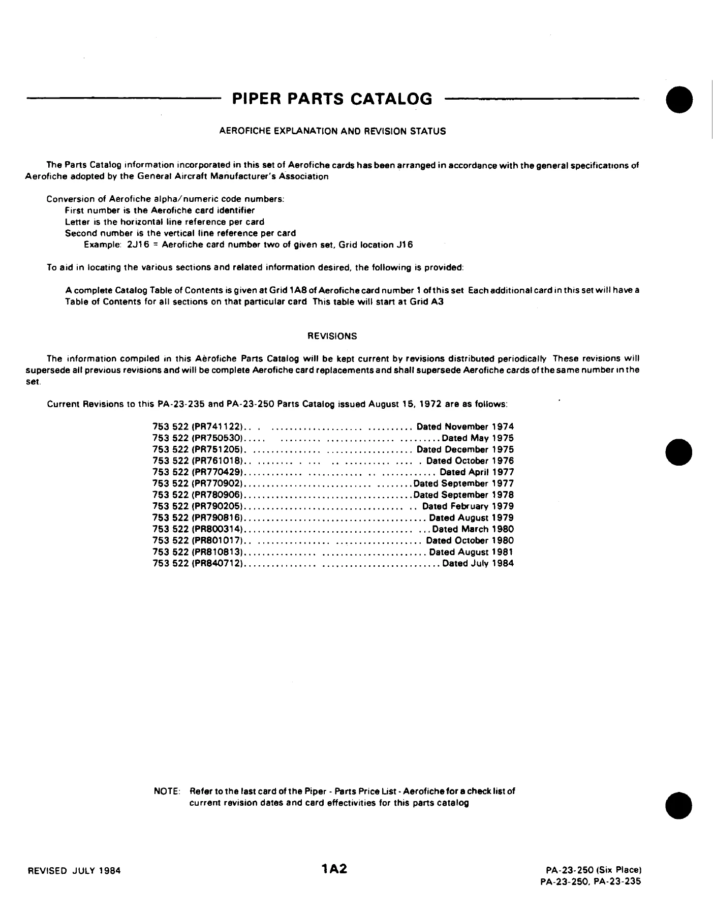
    AEROFICHE EXPLANATION AND REVISION STATUSp. 2
    INTRODUCTIONp. 3
    TABLE OF CONTENTSp. 8
    FIGURE 1. VIEW OF COMPLETE AIRPLANEp. 13
    SECTION I – WING GROUPp. 14
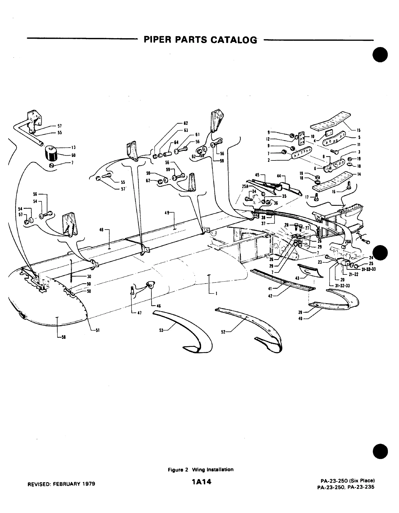
    FIGURE 2. WING INSTALLATIONp. 14
    FIGURE 2A. FLAP ASSEMBLY AND AILERON ASSEMBLYp. 19
    FIGURE 3. WING AND WING TIP CONSTRUCTIONp. 24
    FIGURE 4. WING AND WING TIP SKINp. 31
    SECTION II – FUSELAGE GROUPp. 35
    FIGURE 5. COMPLETE FUSELAGEp. 35
    FIGURE 6. FUSELAGE FORWARD SECTION (PA-23-235, PA-23-250)p. 38
    FIGURE 6A. FUSELAGE FORWARD SECTION (PA-23-250(6))p. 43
    FIGURE 7. FUSELAGE CENTER SECTIONp. 53
    FIGURE 7A. FUSELAGE BOTTOM FAIRINGp. 60
    FIGURE 8. FUSELAGE AFT SECTIONp. 64
    FIGURE 9. FUSELAGE FRAMEp. 72
    FIGURE 10. INSTRUMENT PANEL INSTALLATION (PA-23-235/250/250(6))p. 76
    FIGURE 10A. INSTRUMENT PANEL INSTALLATION (PA-23-250(6))p. 87
    FIGURE 10B. INSTRUMENT PANEL INSTALLATION (PA-23-250(6))p. 97
    FIGURE 10C. INSTRUMENT PANEL INSTALLATION (PA-23-250(6))p. 102
    FIGURE 10D. DUAL INSTRUMENT PANEL INSTALLATION (PA-23-250(6))p. 107
    FIGURE 10E. DUAL INSTRUMENT PANEL INSTALLATION (PA-23-250(6))p. 111
    FIGURE 10F. DUAL INSTRUMENT LINES AND RIGHT PITOT STATIC SYSTEM INSTALLATIONp. 114
    FIGURE 11. CONTROL PEDESTAL INSTALLATIONp. 116
    FIGURE 12. FLOORBOARD AND COCKPIT FINISHING INSTALLATION (PA-23-235/250/250(6))p. 122
    FIGURE 12A. COCKPIT FINISHING INSTALLATION (PA-23-250(6))p. 142
    FIGURE 12B. FLOORBOARD INSTALLATION (PA-23-250(6))p. 152
    FIGURE 13. WINDOW CURTAINS INSTALLATIONp. 156
    FIGURE 14. FUSELAGE ENCLOSURE INSTALLATIONp. 160
    FIGURE 15. BAGGAGE DOOR ASSEMBLY AND CABIN DOOR ASSEMBLY (PA-23-235/250/250(6))p. 168
    FIGURE 15A. BAGGAGE DOOR ASSEMBLY AND CABIN DOOR ASSEMBLY (PA-23-250(6))p. 177
    FIGURE 16. OXYGEN SYSTEM INSTALLATION (PA-23-250)p. 181
    FIGURE 16A. OXYGEN SYSTEM INSTALLATION (PA-23-250(6))p. 184
    FIGURE 16B. OXYGEN SYSTEM INSTALLATION (PA-23-250(6))p. 187
    FIGURE 16C. OXYGEN SYSTEM INSTALLATION (PA-23-250(6))p. 190
    FIGURE 17. SEATS INSTALLATION (PA-23-235/250/250(6))p. 193
    FIGURE 17A. SEATS INSTALLATION (PA-23-250(6))p. 208
    FIGURE 17B. SEATS INSTALLATION (PA-23-250(6))p. 217
    FIGURE 18. VACUUM PUMP INSTALLATION (PA-235/250/250(6))p. 222
    FIGURE 18A. VACUUM PUMP INSTALLATION (PA-23-250(6))p. 227
    FIGURE 19. AIRSPEED, STATIC, OIL PRESSURE AND MANIFOLD PRESSURE LINESp. 231
    FIGURE 20. VENTILATING SYSTEM INSTALLATION (PA-23-235/250/250(6))p. 236
    FIGURE 20A. VENTILATING SYSTEM INSTALLATION (PA-23-250(6))p. 239
    FIGURE 20B. VENTILATING SYSTEM INSTALLATION (PA-23-250(6))p. 242
    FIGURE 21. HEATER INSTALLATION (PA-23-235/250/250(6))p. 244
    FIGURE 21A. HEATER INSTALLATION (PA-23-250(6))p. 248
    FIGURE 22. HEATER ASSEMBLY (STEWART WARNER)p. 252
    SECTION II – FUSELAGE GROUPp. 260
    FIGURE 22A. JANITROL HEATER ASSEMBLYp. 260
    FIGURE 22B. JANITROL HEATER COMPONENTSp. 264
    SECTION III – CHASSIS GROUPp. 267
    FIGURE 23. GEAR STRUT ASSEMBLIESp. 267
    FIGURE 24. NOSE GEAR INSTALLATIONp. 270
    FIGURE 24A. NOSE WHEEL ASSEMBLYp. 275
    FIGURE 25. MAIN GEAR INSTALLATIONp. 278
    FIGURE 26. MAIN WHEEL ASSEMBLYp. 282
    FIGURE 27. BRAKE INSTALLATIONp. 284
    FIGURE 27A. DUAL BRAKE INSTALLATIONp. 287
    FIGURE 28. BRAKE ASSEMBLYp. 290
    SECTION IV – TAIL SURFACES GROUPp. 293
    FIGURE 29. TAIL INSTALLATIONp. 293
    FIGURE 29A. STABILATOR ASSEMBLY (PA-23-235/250/250(6))p. 297
    FIGURE 29B. STABILATOR ASSEMBLY (PA-23-250(6))p. 299
    FIGURE 29C. RUDDER ASSEMBLYp. 302
    FIGURE 29D. FIN ASSEMBLYp. 305
    SECTION V – POWER PLANT GROUPp. 308
    FIGURE 30. POWER PLANT INSTALLATION (PA-23-235/250/250(6))p. 308
    FIGURE 30A. POWER PLANT INSTALLATION (PA-23/250(6))p. 311
    FIGURE 30B. TURBOCHARGER INSTALLATION (AIRESEARCH)p. 316
    FIGURE 30C. TURBOCHARGER INSTALLATION (LYCOMING)p. 318
    FIGURE 31. PROPELLER (PA-23-235/250/250(6))p. 323
    FIGURE 31A. PROPELLER (PA-23-250(6))p. 326
    FIGURE 31B. PROPELLER SYNCHRONIZER SYSTEM INSTALLATIONp. 330
    FIGURE 31C. PROPELLER SYNCHROPHASER SYSTEM INSTALLATIONp. 332
    FIGURE 32. ENGINE BAFFLE INSTALLATIONp. 334
    FIGURE 33. EXHAUST COLLECTORS INSTALLATION (PA-23-235/250/250(6))p. 337
    FIGURE 33A. EXHAUST SYSTEM INSTALLATION (PA-23-250(6))p. 339
    FIGURE 34. NACELLE INSTALLATION (PA-23-235/250/250(6))p. 341
    FIGURE 34A. NACELLE INSTALLATION (PA-23-250(6))p. 345
    FIGURE 34B. NACELLE INSTALLATION (LYCOMING TURBOCHARGER)p. 352
    SECTION VI – FUEL SYSTEM GROUPp. 357
    FIGURE 35. FUEL SYSTEM INSTALLATION (PA-23-235/250/250(6))p. 357
    FIGURE 35A. FUEL INJECTION SYSTEM INSTALLATION (PA-23-250(6))p. 364
    FIGURE 35B. FUEL SYSTEM INSTALLATION (PA-23-250(6))p. 368
    FIGURE 36. FUEL CELL INSTALLATION (PA-23-235/250/250(6))p. 374
    FIGURE 36A. FUEL CELL INSTALLATION (PA-23-250(6))p. 378
    FIGURE 36B. WING TIP FUEL TANK INSTALLATION (PA-23-250(6))p. 381
    FIGURE 37. FUEL SYSTEM CONTROL BOX (PA-23-235/250/250(6))p. 383
    FIGURE 37A. FUEL SYSTEM CONTROL BOX (PA-23-250(6))p. 387
    SECTION VII – ELECTRICAL SYSTEM GROUPp. 390
    FIGURE 38. FUSELAGE ELECTRICAL SYSTEM INSTALLATION (PA-23-235/250)p. 390
    FIGURE 38A. FUSELAGE ELECTRICAL SYSTEM INSTALLATION (PA-23-250(6))p. 393
    FIGURE 38B. WING ELECTRICAL SYSTEM INSTALLATION (PA-23-235/250)p. 399
    FIGURE 38C. WING ELECTRICAL SYSTEM INSTALLATION (PA-23-250(6))p. 402
    FIGURE 38D. BATTERY BOX INSTALLATION (PA-23-235/250)p. 406
    FIGURE 38E. BATTERY BOX INSTALLATION (14-VOLT) (PA-23-250(6))p. 408
    FIGURE 38F. BATTERY BOX INSTALLATION (28-VOLT) (PA-23-250(6))p. 411
    FIGURE 38G. BATTERY BOX INSTALLATION (28-VOLT) (PA-23-250(6))p. 414
    FIGURE 39. PEDESTAL ELECTRICAL INSTALLATIONp. 416
    FIGURE 39A. INSTRUMENT PANEL ELECTRICAL INSTALLATION (PA-23-235/250/250(6))p. 419
    FIGURE 39B. INSTRUMENT PANEL ELECTRICAL INSTALLATION (PA-23-250(6))p. 423
    FIGURE 39C. INSTRUMENT PANEL ELECTRICAL INSTALLATION (PA-23-250(6))p. 426
    FIGURE 40. TAXI LIGHT INSTALLATIONp. 430
    FIGURE 40A. STROBE LIGHTS INSTALLATIONp. 432
    FIGURE 41. EXTERNAL POWER SUPPLY (PA-23-235/250/250(6))p. 435
    FIGURE 41A. EXTERNAL POWER SUPPLY (PA-23-250(6))p. 438
    FIGURE 42. PROPELLER DEICER INSTALLATION (PA-23-250)p. 440
    FIGURE 42A. PROPELLER DEICER INSTALLATION (PA-23-250(6))p. 442
    FIGURE 42B. PNEUMATIC DEICER INSTALLATION (B. F. GOODRICH)p. 445
    FIGURE 42C. PNEUMATIC DEICER INSTALLATION (B. F. GOODRICH)p. 451
    FIGURE 42D. PNEUMATIC DEICER INSTALLATION (AIRBORNE/GOODYEAR) (PA-23-250(6))p. 455
    SECTION VIII – HYDRAULIC SYSTEM GROUPp. 459
    FIGURE 43. HYDRAULIC SYSTEM INSTALLATION (PA-23-235/250/250(6))p. 459
    FIGURE 43A. FUSELAGE HYDRAULIC SYSTEM INSTALLATION (PA-23-250(6))p. 465
    FIGURE 43B. WING HYDRAULIC SYSTEM INSTALLATION (PA-23-250(6))p. 469
    FIGURE 43C. HYDRAULIC SYSTEM COMPONENTS (PA-23-250(6))p. 472
    FIGURE 44. LANDING GEAR ANTI-RETRACTION VALVE INSTALLATIONp. 476
    FIGURE 45. HYDRAULIC POWERPAK COMPONENTSp. 478
    FIGURE 45A. HYDRAULIC POWERPAK COMPONENTSp. 482
    FIGURE 46. EMERGENCY GEAR EXTENDER INSTALLATION (PA-23-235/250/250(6))p. 485
    SECTION IX – CONTROL SYSTEM GROUPp. 488
    FIGURE 47. ENGINE CONTROLS INSTALLATIONp. 488
    FIGURE 48. STABILATOR CONTROL INSTALLATIONp. 491
    FIGURE 49. AILERON CONTROLS INSTALLATIONp. 494
    FIGURE 50. RUDDER CONTROL INSTALLATIONp. 497
    FIGURE 51. TAIL TRIM MECHANISM INSTALLATIONp. 500
    FIGURE 51A. TRIM TAB INTERCONNECT SYSTEM INSTALLATIONp. 506
    SECTION X – ELECTRONICS GROUPp. 513
    FIGURE 52. COLLINS AND ARC RADIO INSTALLATIONp. 513
    FIGURE 53. RADIO JUNCTION BOXES (PA-23-235/250/250(6))p. 517
    FIGURE 54. RADIO JUNCTION BOXES (PA-23-250(6))p. 521
    FIGURE 54A. RADIO JUNCTION BOXES (14-VOLT) (PA-23-250(6))p. 523
    FIGURE 54B. RADIO JUNCTION BOXES (28-VOLT) (PA-23-250(6))p. 525
    FIGURE 55. ALL WEATHER ANTENNA INSTALLATIONp. 527
    FIGURE 55A. PIPER AUTOMATIC LOCATOR (ELT) INSTALLATION (GARRETT MFG. LTD)p. 529
    FIGURE 55B. PIPER AUTOMATIC LOCATOR (ELT) INSTALLATION (COMMUNICATIONS COMPONENTS CORP)p. 531
    FIGURE 55C. PIPER AUTOMATIC LOCATOR (ELT) INSTALLATION (NARCO AVIONICS)p. 533
    FIGURE 56. PIPER PM-1 MARKER BEACON INSTALLATION (PA-23-250(6))p. 535
    FIGURE 57. AUTOCONTROL I INSTALLATIONp. 538
    FIGURE 58. AUTOCONTROL II INSTALLATIONp. 541
    FIGURE 59. AUTOCONTROL III INSTALLATION (PA-23-250(6))p. 544
    FIGURE 59A. AUTOCONTROL III B INSTALLATION (PA-23-250(6))p. 546
    FIGURE 60. ALTIMATIC PILOT I INSTALLATIONp. 548
    FIGURE 61. ALTIMATIC PILOT II INSTALLATIONp. 551
    FIGURE 61A. ALTIMATIC PILOT III AND III B INSTALLATIONp. 556
    FIGURE 62. ALTIMATIC PILOT II B-1 INSTALLATIONp. 560
    FIGURE 63. ALTIMATIC PILOT III C INSTALLATION (PA-23-250(6))p. 563
    FIGURE 64. ALTIMATIC X F/D AUTOPILOT INSTALLATION (PA-23-250(6))p. 567
    FIGURE 65. ALTIMATIC X AUTOPILOT INSTALLATION (PA-23-250(6))p. 570
    FIGURE 66. ALTIMATIC V F/D AND V F/D-1 AUTOPILOT INSTALLATION (PA-23-250(6))p. 573
    FIGURE 67. ALTIMATIC V AND V-1 AUTOPILOT INSTALLATION (PA-23-250(6))p. 579
    FIGURE 68. AUTOPILOT/FLIGHT DIRECTOR INSTALLATION (BENDIX FCS-810) (PA-23-250(6))p. 583
    FIGURE 69. AUTOPILOT INSTALLATION (BENDIX FCS-810) (PA-23-250(6))p. 586
    FIGURE 69A. KING AUTOPILOT (KAP-200) AND KING AUTOPILOT F/D (KFC-200) INSTALLATIONp. 589
    FIGURE 70 .RADAR ALTIMETER INSTALLATION (PA-23-250(6))p. 591
    FIGURE 71. GLIDE SLOPE COUPLER INSTALLATION (PA-23-250(6))p. 593
    FIGURE 72. RADIO MAGNETIC INDICATOR INSTALLATION (PA-23-250(6))p. 595
    FIGURE 73. KING RADAR INSTALLATION (KWX-40) (PA-23-250(6))p. 597
    FIGURE 74. BENDIX RADAR INSTALLATION (RDR-150) (PA-23-250(6))p. 599
    FIGURE 75. ENCODING ALTIMETER INSTALLATION (PA-23-250(6))p. 602
    RADIO INSTALLATION AND WIRING DIAGRAM DRAWINGSp. 604
    SECTION XI – MISCELLANEOUS GROUPp. 613
    OPTIONAL EQUIPMENT KITS, REPAIR KITS AND SPECIAL TOOLSp. 613
    DECALSp. 619
    NUMERICAL INDEXp. 627

  • Section II — Fuselage Group
    • Complete Fuselage
    • Fuselage Forward Section (PA-23-235 and PA-23-250)
    • Fuselage Forward Section (PA-23-250 Six Place)
    • Fuselage Center Section
    • Fuselage Bottom Fairing
    • Fuselage Aft Section
    • Fuselage Frame Assembly
    • Instrument Panel Installation (Serial Nos. 27-1 to 27-3836, 27-3838 to 27-3943)
    • Instrument Panel Installation (Serial Nos. 27-3837, 27-3944 to 27-7305234)
    • Instrument Panel Installation (Serial Nos. 27-7305222, 27-7405235 to 27-7405476)
    • Instrument Panel Installation (Serial Nos. 27-7554001 and up)
    • Dual Instrument Panel Installation (Serial Nos. 27-7405235 to 27-7405476)
    • Dual Instrument Panel Installation (Serial Nos. 27-7554001 and up)
    • Dual Instrument Lines and Right Pitot Static System Installation
    • Control Pedestal Installation
    • Floorboard and Cockpit Finishing Installation
    • Window Curtains Installation
    • Fuselage Enclosure Installation
    • Baggage Door Assembly and Cabin Door Assembly
    • Oxygen System Installation
    • Seats Installation
    • Vacuum Pump Installation
    • Airspeed, Static, Oil Pressure and Manifold Pressure Lines
    • Ventilating System Installation
    • Heater Installation & Stewart Warner / Janitrol Heater Assemblies
  • Section III — Chassis Group
    • Gear Strut Assemblies
    • Nose Gear Installation & Nose Wheel Assembly
    • Main Gear Installation & Main Wheel Assembly
    • Brake Installation, Dual Brake Installation & Brake Assembly
  • Section IV — Tail Surfaces Group
    • Tail Installation
    • Stabilator Assembly
    • Rudder Assembly & Fin Assembly
  • Section V — Power Plant Group
    • Power Plant Installation
    • Turbocharger Installation (Airesearch and Lycoming)
    • Propeller & Governor Linkages
    • Propeller Synchronizer & Synchrophaser Systems
    • Engine Baffles, Exhaust Collectors & Nacelle Installations
  • Section VI — Fuel System Group
    • Fuel System & Fuel Injection System Installations
    • Fuel Cell Installation & Wing Tip Fuel Tank Installation
    • Fuel System Control Box
  • Section VII — Electrical System Group
    • Fuselage and Wing Electrical Wiring Installations
    • Battery Box Installations (14-Volt and 28-Volt)
    • Pedestal and Instrument Panel Electrical Harnesses
    • Lighting Systems (Taxi, Strobe, Post, and Glar-Ban)
    • External Power Supply & Deicer Systems (Propeller and Pneumatic)
  • Section VIII — Hydraulic System Group
    • Hydraulic Powerpak Components & System Installations
    • Wing and Fuselage Hydraulic Plumbing
    • Landing Gear Anti-Retraction Valve & Emergency Gear Extender
  • Section IX — Control System Group
    • Engine Controls, Pedestal Levers, and Push-Pulls
    • Stabilator, Aileron, and Rudder Cable Control Systems
    • Tail Trim Mechanism & Trim Tab Interconnect System

    IMAGES PREVIEW

    Piper Aztec PA-23-250 & Apache PA-23-235 Illustrated Parts Catalog — PDF page 2 preview
    Piper Aztec PA-23-250 & Apache PA-23-235 Illustrated Parts Catalog — PDF page 14 preview
    Piper Aztec PA-23-250 & Apache PA-23-235 Illustrated Parts Catalog — PDF page 20 preview

  • Section X — Electronics Group
    • Avionics Installations (Collins, ARC, King, Narco, and Bendix)
    • Radio Junction Boxes (14V and 28V) & Antennas
    • Emergency Locator Transmitter (ELT) Installations
    • Autopilot Systems (AutoControl I, II, III, IIIB; AltiMatic I, II, III, IIIB-1, IIIC, V, V F/D, X)
    • Flight Director, Weather Radar, and Encoding Altimeter Installations
  • Section XI — Miscellaneous Group
    • Optional Equipment Kits, Repair Kits, Special Service Tools, and Airframe Decals
    • Complete Numerical Part Number Index

For aircraft technicians, airframe and powerplant mechanics, and restoration shops, having the complete Piper Aztec PA-23-250 & Apache PA-23-235 Illustrated Parts Catalog provides the definitive factory record of every individual casting, bracket, structural rib, plumbing line, and piece of hardware across the airframe. By detailing exact part numbers alongside clear exploded structural views, this catalog eliminates guesswork when sourcing replacement components, verifying airframe serial effectivity, confirming hardware specifications, and disassembling or reassembling complex mechanical linkages.

Essential Parts Reference for Maintenance and Maintenance Compliance

Working on multi-engine aircraft demands absolute adherence to certified parts standards. This Piper Aztec PA-23-250 & Apache PA-23-235 Illustrated Parts Catalog enables technicians and owners to verify component authenticity, trace part supersessions, cross-reference AN and MS attachment hardware, and accurately execute airframe repairs, annual inspections, and structural rebuilds. Delivered as an instant high-quality digital PDF download, this manual is immediately accessible on desktop computers, workshop laptops, and tablets in the hangar, and allows individual pages or entire sections to be printed on demand for hands-on reference at the aircraft.
Reviews

There are no reviews yet.

Be the first to review “Piper Aztec PA-23-250 & Apache PA-23-235 Illustrated Parts Catalog”

What Our Customers Say

★★★★★ Live reviews from customers
Loading customer reviews...
0
    0
    Your Cart
    Your cart is emptyReturn to Shop
    🛒
    Recently Purchased
    🕒 verified order