
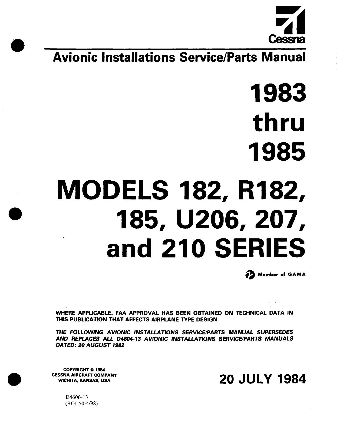
1983-1985 Cessna 182 R182 185 U206 207 210 Avionics Service Parts Manual
Original price was: $34.95.$21.95Current price is: $21.95.
Complete avionics installations service and parts manual for 1983 through 1985 Cessna 182, R182, 185, U206, 207 and 210 series aircraft. Covers Sperry and vendor avionics, antenna and audio systems, autopilot rigging procedures, loading charts, numerical parts index and full wiring diagrams. 910 pages, document D4606-13.
Description
1983-1985 Cessna 182 R182 185 U206 207 210 Avionics Service Parts Manual
This is the reissued avionics installations service and parts manual covering the 1983 through 1985 model years of the Cessna 182, R182, 185, U206, 207 and 210 series aircraft. It is a working document built for the radio service technician: it pairs illustrated parts breakdowns with installation drawings, wiring schematics and complete autopilot rigging procedures for the avionics equipment fitted to these airframes. The publication number is D4606-13, dated 20 July 1984, and it supersedes and replaces all D4604-13 manuals dated 20 August 1982. The 1983-1985 Cessna 182 R182 185 U206 207 210 Avionics Service Parts Manual is issued with the addition of closing serial numbers to the cross-reference listing.
File Details
- Manual type: Avionics installations service and parts manual
- Applicable aircraft: Cessna 182, R182, 185, U206, 207 and 210 series
- Model years: 1983 through 1985
- Document number: D4606-13 (paper copy); D4606-13AF (aerofiche)
- Manual date: 20 July 1984 (reissue)
- Temporary revision: D4606TR1-13, dated 11 July 1997
- Supersedes: D4604-13, dated 20 August 1982
- Language: English
- Page count: 910 pages
- File format: PDF
Chapters Covered
The manual is organised into nine sections:
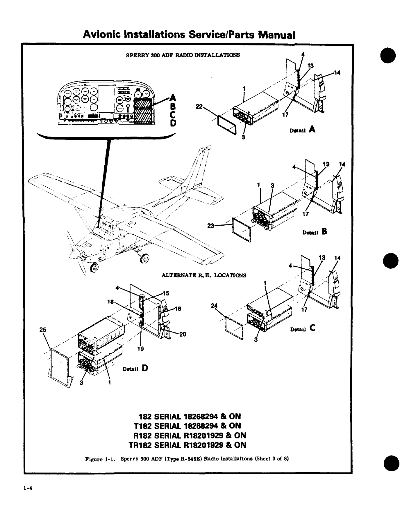
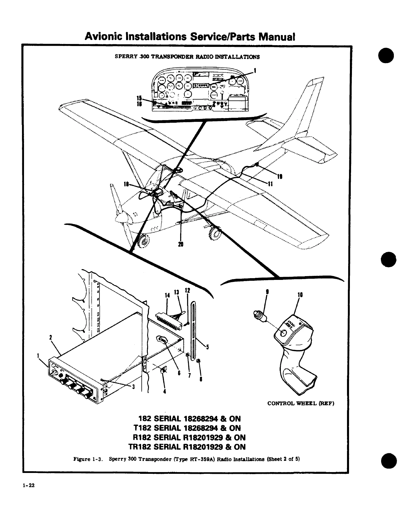
- Section I – Cessna Crafted Avionics Equipment: Sperry 300 ADF (R-546E), Sperry 300 Nav/Com (RT-385A), Sperry 300 Transponder (RT-359A), Sperry 400 ADF (R-446A), Sperry 400 Nav/Com (RT-485B) with 300 and 400 series indicators, Sperry 400 Area Nav (RN-478A and RN-479A), Sperry 400 Glide Slope (R-443B), Sperry 400 Marker Beacon (R-402A), Sperry 400 DME (R-476A and RT-477A), Sperry 400 Transponder (R-495A), Sperry 400 Encoding Altimeter (EA-401A), Sperry Radio Magnetic Indicator (IN-404A), Sperry unslaved and slaved Horizontal Situation Indicators (IG-832C and IG-832A), Sperry 200A Autopilot (AF-295B) per model, Sperry 300A Autopilot (AF-395A) per model, Cessna 400B Autopilot (AF-550A) per model, Cessna 400B Integrated Flight Control System (IF-550A), and the Cessna 800 Altitude Encoder with Alerter and Pre-Select.
- Section II – Vendor Crafted Avionics Equipment: AM/FM radio with stereo cassette player (EC-100), blind altitude encoder, Bendix weather radar (RDR-160), Primus 100 WX weather radar, emergency locator transmitter, Collins Area Navigation (ANS-351C), Collins DME (450C), Sunair Single Side-Band (ASB-125), Terra Radar Altimeter (TRA 2500), King radio telephone (KT96), King Area Navigation (KNS81), King Audio Control System (KMA24), King Digital ADF (KR87), King Digital Com (KY196), King DME (KN63), King Nav/Com with glideslope (KX165), King radar altimeter (KRA10A), King Radio Magnetic Indicator (KI229), King transponder (KT79) with optional blind encoder or encoding altimeter, and King Colour Radar (KWX56).
- Section III – Antenna Systems: VHF antenna and VHF com blade antenna installations, combination UHF glideslope and VHF omni antennas, balanced loop antennas, marker beacon antennas, medium and high frequency fixed wire antennas, ADF sense antennas, anti-precipitation ADF sense antennas, transponder and DME antennas, Collins DME antenna (ANT-450C), and the AM/FM stereo cassette antenna.
- Section IV – Audio Systems: Incandescent and electroluminescent lighted audio control panels for one, two or three transmitters and dual ADFs, potentiometer adjustment procedures, speaker installations, hand-held microphone installations, headset installations, headset/microphone installations and padded headset/microphone combinations.
- Section V – Miscellaneous Avionics Equipment: Radio cooling installations, radio noise filter installations, avionics circuit breaker panel installations, 400B autopilot accessory unit extender cable, and ground block installations.
- Section VI – Avionics Loading Charts: Per-model weight and balance loading data for 185, 182, R182, U206 and 207, 210 and T210, and P210 configurations.
- Section VII – Autopilot Rigging Procedures: Cessna 200A and 300A autopilot rigging per model series, plus 400B and 400B IFCS rigging for R182, U206, 210 and P210.
- Section VIII – Numerical Index: Part-number index cross-referenced to figure and page.
- Section IX – Avionics Wiring Diagrams: Diagram set 3920163 through 3920315 covering radio cooling, Sunair SSB, HSI/DG, slaved directional gyro, IFCS circuit board schematics, transponders, encoding altimeters, blind encoders, 200A and 300A Navomatic, control wheel mic key, altitude alerter, Sperry 400 DME, weather radar, autopilot accessory units, 400B IFCS, radio magnetic indicators, digital ADF, radio cooling, audio/marker beacon panels, interphone amplifier, Collins DME, Collins RNAV, King KMA24, King KY196, King KT96, King KNS81, King KI229, King HSI, King KT79, King KN63, Terra radar altimeter, 400 glideslope, radio cooling fan, all-purpose control wheel, 400B IFCS with King avionics, King KY196 as comm 1, King KNS81 as nav 1, King KR87, Sperry RN-479A, Sperry RTA-477A, warning board, encoding altimeter with King transponder, King KI229, 400B autopilot with King avionics, and control wheel mic key and intercom.
What ties this document together is that it treats avionics as an installed system rather than a shelf of black boxes. Every radio entry carries its mounting hardware, support brackets, doublers, bezels, circuit breakers and connectors, so a technician can identify not just the receiver but the tray, the adapter plate and the rack that holds it in a particular airframe. Because the manual is split by section rather than by aircraft, the same Sperry 400 Nav/Com appears under several figure numbers with the different mounting provisions used on a 182 versus a 210 versus a P210. Antenna runs, feed-through insulators, wire lengths, sealing notes and tension figures are given in place rather than summarised, which is what makes the installation figures usable on the hangar floor.
Serial Number Coverage
The cross-reference listing in the front of the manual maps popular names to model numbers and serial ranges:
- Skylane and Skylane II: model 182, 1983 through 1986, serial 18268294 through 18268586
- Turbo Skylane and Turbo Skylane II: model T182, 1983 through 1985, serial 18268294 through 18268541
- Skylane RG and Skylane RG II: model R182, 1983 through 1986, serial R18201929 through R18202039 and R18201315
- Turbo Skylane RG and Turbo Skylane RG II: model TR182, 1983 through 1986, serial R18201929 through R18202039 and R18201315
- 185 Skywagon and 185 Skywagon II: model A185F, 1983 through 1985, serial 18504395 through 18504448
- Stationair 6 and Stationair 6 II: model U206G, 1983 through 1986, serial U20606700 through U20607020
- Turbo Stationair 6 and Turbo Stationair 6 II: model TU206G, 1983 through 1986, serial U20606700 through U20607020
- Stationair 8 and Stationair 8 II: model 207A, 1983 through 1984, serial 20700763 through 20700788
- Turbo Stationair 8 and Turbo Stationair 8 II: model T207A, 1983 through 1984, serial 20700763 through 20700788
- Centurion and Centurion II: model 210N, 1983 through 1986, serial 21064773 through 21065009
- Turbo Centurion and Turbo Centurion II: model T210N, 1983 through 1986, serial 21064773 through 21065009
- Pressurized Centurion and Pressurized Centurion II: model P210R, 1983 through 1986, serial P21000812 through P21000874
Where an effectivity range in the manual ends with the statement “… & ON”, the cross-reference table above supplies the applicable ending serial number for that model.
How the Parts Listings Are Organised
The 1983-1985 Cessna 182 R182 185 U206 207 210 Avionics Service Parts Manual uses a figure-and-index parts structure. Each parts list opens with a figure number followed by a dash and the indexed number. Part numbers identify the item, and the description column shows relationship by degree of indentation — a radio installation sits in the first column, the receiver is the next lower assembly in the second. Attaching parts are listed immediately beneath the item they attach and are closed with a separating symbol. Left-hand and right-hand assemblies that share most components are listed together with the differing parts coded. Standard hardware appears under AN, MS and NAS numbers, while parts in the Cessna Standard System carry the prefix “S”.
Serial usage is handled with a letter code in the usable-on column at the far right of the parts page. Codes apply only to the figure they appear on, and the letters are defined at the end of that figure. Where no usable-on code appears against a first-column item, the part applies to all models and serials in the manual. Non-interchangeable parts are all listed with their individual usage codes, while interchangeable later design parts carry the note “when exhausted use” following the earlier design part number.
Bulk items such as coaxial cable, antenna wire and clamps are noted as bulk and are supplied in the most convenient length or quantity, with the cut length or quantity per installation given for reference. This matters when ordering because it tells you whether you are buying a piece of RG58A/U by the foot or a cut-to-length assembly.
Ordering Information Included
The front matter documents how avionic parts are ordered from each source. Sperry Radio Systems Division orders go by mail to the Sperry Corporation, Sperry Radio Systems Division, P.O. Box 52029, Phoenix, Arizona 85072. King Radio Corporation orders go by telephone at 800-255-5464, by telex at WUD (0) 4-2299, by cable as KINGRAD, or by mail to King Radio Corporation, 400 North Rogers Road, Olathe, KS 66062. The manual also explains the dealer and distributor ordering chain, what the factory will and will not honour, and how to mark corrosion-proofing requests using the letters “CP” following the part number. Model and serial number of the aircraft are called out as essential when ordering.
What This Manual Lets You Do
With the 1983-1985 Cessna 182 R182 185 U206 207 210 Avionics Service Parts Manual on hand, a technician can identify the avionics package fitted to a specific serial number, trace a fault back through the installation wiring rather than just the box, and order the correct mounting hardware, connectors, circuit breakers and antenna components the first time. The wiring diagram section alone covers the full interconnect path for Sperry, Collins and King equipment across the six model series, which is the difference between a guess and a diagnosis. The autopilot rigging procedures give the cable tension figures, chain deflection, clutch torque settings, friction band limits and travel times needed to bring a 200A, 300A, 400B or 400B IFCS installation back into specification after service.
Getting these values right matters. Aileron cable tension on a 400B is set to 10 to 13 pounds on the R182 and U206 and to 10 plus or minus 3 on the 210 series, elevator tension differs by model, and the trim tab clutch must lift 14 pounds but slip at 22. Rigging an autopilot outside those numbers produces a system that flies, but flies badly, and it will not show up until the aircraft is airborne. The same reasoning applies to avionics cooling duct routing and circuit breaker amperage — the manual notes that circuit breaker amperage changes with the radio complement, so the parts list deliberately calls out only the base part number and instructs the technician to use the number on the face of the breaker.
Because this is a reference document for a serial-number-limited production run, a large portion of the avionics and mounting hardware it describes has not been catalogued anywhere else in this level of detail. The installation figures show the actual support brackets, doublers, blast tubes and feed-through locations used on each airframe, which is what you need when a field installation has to match a factory one.
IMAGES PREVIEW
Instant PDF Delivery
The manual is delivered as an instant PDF download after purchase. There is no shipping, no waiting on a physical binder, and no risk of a missing page in a used paper copy. Open it on a laptop, tablet or phone in the hangar or at the bench, zoom into the exploded views and wiring diagrams, and print the specific figure pages you need for the job in front of you. The 1983-1985 Cessna 182 R182 185 U206 207 210 Avionics Service Parts Manual is a working document, and a printable PDF is how it works best.
Reviews
There are no reviews yet.