
Piper PA-34-200 Seneca Service Manual 1972-1974 Airplane Repair PDF
Original price was: $39.95.$23.95Current price is: $23.95.
Complete Piper PA-34-200 Seneca service manual covering 1972, 1973, and 1974 models with serial numbers 34-7250001 through 34-7450220. This 4-card PDF includes airworthiness limitations, inspection procedures, structures, surface controls, hydraulic system, landing gear, powerplant, fuel system, instruments, electrical, electronics, heating and ventilation, and accessories.
Description
Piper PA-34-200 Seneca Service Manual – Complete Airplane Maintenance Library
This Piper PA-34-200 Seneca Service Manual is the complete four-card publication (P/N 753-817) reissued October 30, 2003, covering airplane serial numbers 34-7250001 through 34-7450220. Whether you are performing a routine 100-hour inspection, troubleshooting a hydraulic fault, rigging flight controls, or overhauling a landing gear oleo, this PA-34-200 Seneca service manual gives you the procedures, specifications, and illustrations Piper published for the Seneca airframe and its systems.
The Seneca is a twin-engine, six-place, low-wing monoplane powered by Lycoming fuel-injected engines. This manual covers both the left-hand rotation IO-360-C1E6 and the right-hand rotation LIO-360-C1E6 installations, along with the Hartzell constant-speed propellers, the hydraulically retractable tricycle landing gear, and the full electrical and avionics architecture of the aircraft. Every section is written for the mechanic who needs accurate torque values, rigging dimensions, wear limits, and step-by-step removal and installation instructions rather than general guidance.
File Details
- Manual Type: Airplane Service Manual (Instructions for Continued Airworthiness)
- Brand / Manufacturer: Piper Aircraft Corporation / The New Piper Aircraft, Inc.
- Model: PA-34-200 Seneca
- Covered Serial Numbers: 34-7250001 thru 34-7450220
- Model Years: 1972, 1973, 1974
- Document Number: 753-817
- Revision Date: October 30, 2003 (complete reissue)
- Language: English
- Page Count: 810 pages across four aerofiche cards
- File Format: PDF
Chapters Covered
- Section I – Airworthiness Limitations: Fatigue life limits, life-limited part marking and disposition, mandatory replacement intervals including the nose gear drag link upper attach bolt.
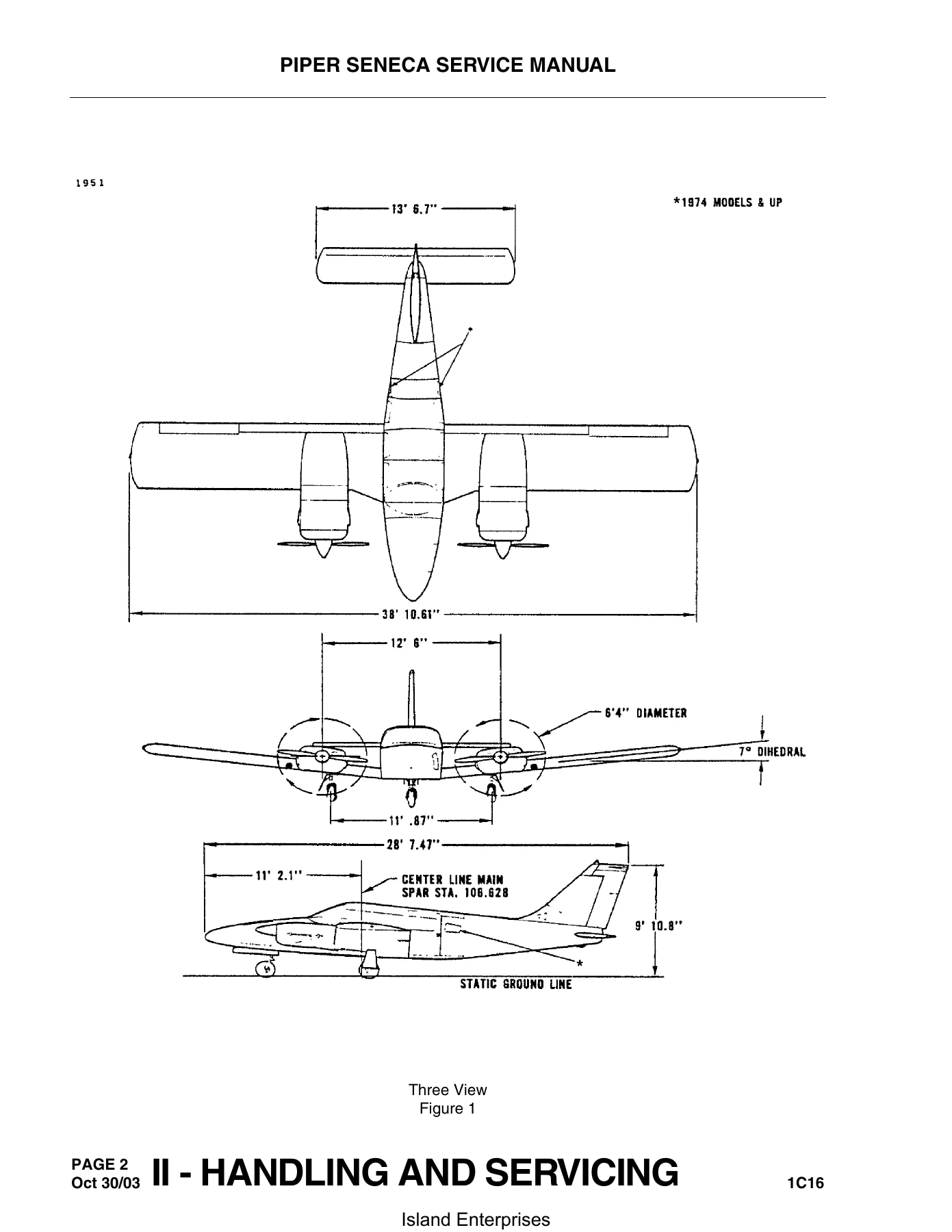
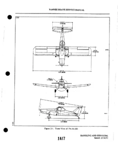
- Section II – Handling and Servicing: Dimensions, station reference lines, weight and balance data, jacking, weighing, leveling, mooring, parking, towing, taxiing, fuel system servicing, brake system servicing, oleo strut filling and inflation, tire balancing, hydraulic system servicing, battery servicing, cleaning procedures, and the complete lubrication chart with consumable materials, vendor contact information, and conversion tables.
- Section III – Inspection: Time limits, scheduled maintenance, definitions, annual and 100-hour inspection procedures, 50/100/500/1000-hour inspection groups for propeller, engine, cabin and cockpit, fuselage and empennage, wing, and landing gear, special inspections by flight hour and calendar year, unscheduled maintenance checks including lightning strike, engine overspeed, hard landing, flood damage, and operation in high dust, salt, humidity, cold, or soft terrain environments.
- Section IV – Structures: Wing group including wing tip, aileron, wing flap, and complete wing removal and installation, aft wing attach fitting corrosion inspection, empennage group with stabilator, rudder, vertical fin, fuselage assembly, windshield, side windows, cabin door window, cockpit and cabin doors, baggage doors, door snubbers, seats, structural repairs for metal, fiberglass, and thermoplastic, safety walk repair, control surface balancing, and cherrylock rivet removal.
- Section V – Surface Controls: Control cable inspection, control column assembly, aileron controls, aileron bellcrank, stabilator controls, stabilator trim controls, rudder pedal assembly, rudder controls, rudder trim controls, flap controls, torque tube and pushrod distortion inspection, and complete rigging and adjustment procedures with fabricated rigging tool dimensions.
- Section VI – Hydraulic System: Description and operation of the Prestolite and Oildyne hydraulic pumps, troubleshooting, pump removal and disassembly, cleaning and inspection, assembly, test and adjustment, installation, landing gear free-fall valve assembly, nose and main gear actuating cylinders, hydraulic lines, system testing, and pump/reservoir servicing.
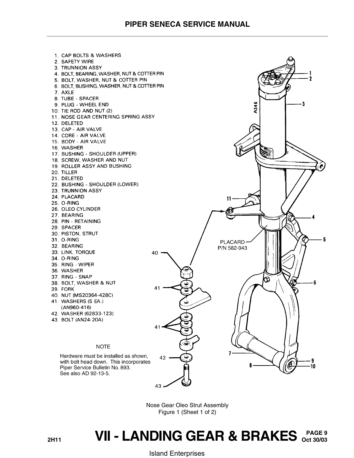
- Section VII – Landing Gear and Brakes: Nose landing gear with oleo strut assembly, modified components, landing gear removal and rigging, 1000-hour nose gear trunnion inspection, 100-hour nose gear drag link upper attach bolt inspection, alignment, door rigging, main landing gear with oleo strut assembly, main gear trunnion inspection, trunnion attach fittings inspection, adjustment, alignment, toe-out correction, door adjustment, landing gear limit switches, squat switch, warning switch, wheels, brake system, wheel brake assembly, brake master cylinder, toe brake cylinders, brake bleeding procedures, and brake system leak check.
- Section VIII – Powerplant: Engine cowling, cowl flaps, propeller removal and installation, blade track checking, propeller governor, engine removal and installation, engine shock mounts, throttle and mixture control adjustment, alternate air door, fuel injector, idle speed and mixture adjustment, fuel-air bleed nozzles, ignition system maintenance, magnetos, timing procedures, harness assembly, spark plugs, lubrication system, oil pressure relief valve, oil screens and filters, exhaust system 25-hour inspection, and heat exchanger 100-hour inspection.
- Section IX – Fuel System: Fuel tanks, inboard and outboard tank removal and installation, fuel system inspection, fuel tank vent obstruction test, fuel quantity sender unit, sender/gauge check, gascolator, fuel selector valve, electric fuel pump, and cleaning the fuel system.
- Section X – Instruments: Face mounted and cluster mounted instrument removal and installation, vacuum system, vacuum system service tips, vacuum gauge, pitot-static system, vacuum filters, vacuum regulators, vacuum pump, directional gyro, gyro horizon, rate of climb indicator, sensitive altimeter, airspeed indicator, magnetic compass, manifold pressure gauge, tachometer indicator, engine oil pressure gauge, fuel pressure gauge, turn and bank, fuel quantity indicator, oil temperature indicator, ammeter, exhaust gas temperature gauge, cylinder head temperature gauge, fuel flow gauge, and instrument markings.
- Section XI – Electrical System: Alternator system, troubleshooting, alternator and components, checking alternator system, overhaul, disassembly, inspection and testing, assembly, testing, alternator service test specifications, belt tension checking, voltage regulator, overvoltage relay, starters, description, operation, troubleshooting, inspection, overhaul, disassembly, brushes, armature, field coils, brush holders, gear and pinion housing, Bendix drive, assembly, bench tests, starting motor control circuit, starting motor service test specifications, battery, servicing, removal, installation, charging, battery box corrosion prevention, external power receptacle, exterior lights, landing and taxi lights, navigation lights, anti-collision strobe lights, interior lights, dimmer control assembly, aluminum wiring, stall warning indicator, horn and lift detectors, and complete electrical schematics.
- Section XII – Electronics: Emergency Locator Transmitter (ELT) description, battery removal and installation for Garrett magnesium, Communications Components Corp. alkaline, and Narco alkaline batteries, pilot’s remote switch, testing, autoflight, Piper Automated Flight Control System equipment, and non-Piper AFCS equipment contacts.
- Section XIII – Heating and Ventilation System: Description and operation, inspection, rigging cabin heat and defrost controls, optional combustion heater (Janitrol), troubleshooting, heater system operational test, operating controls, 50-hour and 100-hour inspections, heater electrical system checks, maintenance, combustion air blower, spark plug, ignition unit, vibrator, cycling switch and limit switch, combustion air pressure switch, fuel regulator and shutoff valve, fuel filter, duct switch, heater overhaul, and optional overhead vent blower.
- Section XIV – Accessories and Utilities: Propeller deicing system description and operation, operational check, troubleshooting, 50-hour and 100-hour inspections, brushes, slip rings, deicers, resistance check, replacement, installation, wrinkled deicers, electrical check, timer test, balancing, final electrical check, pneumatic deicing system, troubleshooting, operational check, electrical test, pressure leakage test, vacuum regulators, inspections, control valves, timer, deicers (boots) removal and installation, repair limits, repair procedure, resurfacing, wing ice inspection light, and restraint system.
Across all fourteen sections, this PA-34-200 Seneca repair manual delivers the full scope of airframe and system maintenance for the Seneca. The inspection program alone walks through every 50, 100, 500, and 1000-hour task, from checking engine mount bushings and lubricating flight controls to inspecting the stabilator attach fittings for corrosion and verifying the main gear trunnion for cracks. The structures section gives you the exact procedures for removing and reinstalling the wing, stabilator, rudder, and vertical fin, including the bolt legend and torque values for the eighteen main spar bolts. In the surface controls section you get the complete rigging sequence for ailerons, stabilator, rudder, and flaps, along with the dimensions for fabricating your own rigging tools. The landing gear and brakes section covers both the nose and main gear oleo struts down to the O-ring and wiper ring level, plus the brake bleeding procedures and toe-out correction chart. The powerplant section takes you through engine removal, magneto timing, fuel injector adjustment, and exhaust system inspection. The electrical section provides the alternator and starter service test specifications, battery servicing, and a full set of wiring schematics indexed by system.
What This Manual Enables You to Do
With this Piper Seneca service manual on hand, you can perform scheduled inspections, diagnose system faults, remove and install major components, rig flight controls to factory tolerances, overhaul landing gear struts and brake cylinders, time magnetos, adjust fuel injectors, service the hydraulic system, and troubleshoot the electrical and avionics systems. The manual includes the airworthiness limitations section that specifies the mandatory 500-hour replacement of the nose gear drag link upper attach bolt, the life-limited part marking requirements, and the inspection intervals that keep the airplane compliant with its type certificate.
Every procedure is supported by the specifications you need to work accurately: torque values for structural bolts and flare fittings, cable tension charts corrected for ambient temperature, control surface travel limits, oleo strut fluid capacities and inflation pressures, engine operating limits, electrical component loads, and wear tolerances for bearings, bushings, and pins. The manual also includes troubleshooting tables for the hydraulic system, landing gear, powerplant, fuel system, electrical system, propeller deicing system, and combustion heater, so you can trace a fault from symptom to cause to remedy without guesswork.
IMAGES PREVIEW
This Piper PA-34-200 Seneca service manual PDF is delivered as an instant download after payment. No shipping, no waiting for a physical book. You can open it on any computer, tablet, or smartphone, search across all four cards, and print the pages you need for the shop. Whether you maintain your own Seneca or work as a mechanic on a customer’s airplane, this manual is the reference that keeps the work correct and the airplane airworthy.
Reviews
There are no reviews yet.