
Piper PA-36-285 PA-36-300 PA-36-375 Pawnee Brave Service Manual 761471
Original price was: $44.95.$26.95Current price is: $26.95.
Complete Piper Pawnee Brave service manual covering the PA-36-285, PA-36-300 and PA-36-375 agricultural aircraft, including Continental and Lycoming power plants, fuel injection, dispersal systems, structures, landing gear, brakes and electrical systems.
Description
Piper PA-36 Pawnee Brave Service Manual 761471 – PA-36-285, PA-36-300 and PA-36-375
This service manual covers the Piper PA-36 Pawnee Brave in all three factory variants: the PA-36-285 with its Teledyne Continental 6-285 Tiara engine, the PA-36-300 with the Avco-Lycoming IO-540-K1G5, and the PA-36-375 with the Avco-Lycoming IO-720-D1CD. It is the same reference technicians have relied on for scheduled inspection, repair, removal and installation work across the Pawnee Brave line, and it walks through every major airframe and power plant system chapter by chapter. Document number 761471, originally issued February 14, 1973 and revised through August 4, 1989.
File Details
- Manual type: Aircraft service and maintenance manual
- Brand: Piper Aircraft Corporation
- Models covered: PA-36-285, PA-36-300, PA-36-375 Pawnee Brave
- Document number: 761 471
- Original issue date: February 14, 1973
- Latest revision listed: August 4, 1989
- Language: English
- File format: PDF
- Structure: Aerofiche card service manual – Card 1 (Sections I through VIIIA) and Card 2 (Sections VIIIB through XIV)
Chapters Covered
- I – Introduction: general description, fuselage, wing, empennage, flight controls, landing gear, engine and propeller, fuel system, instruments, electrical system, environmental control, accessories
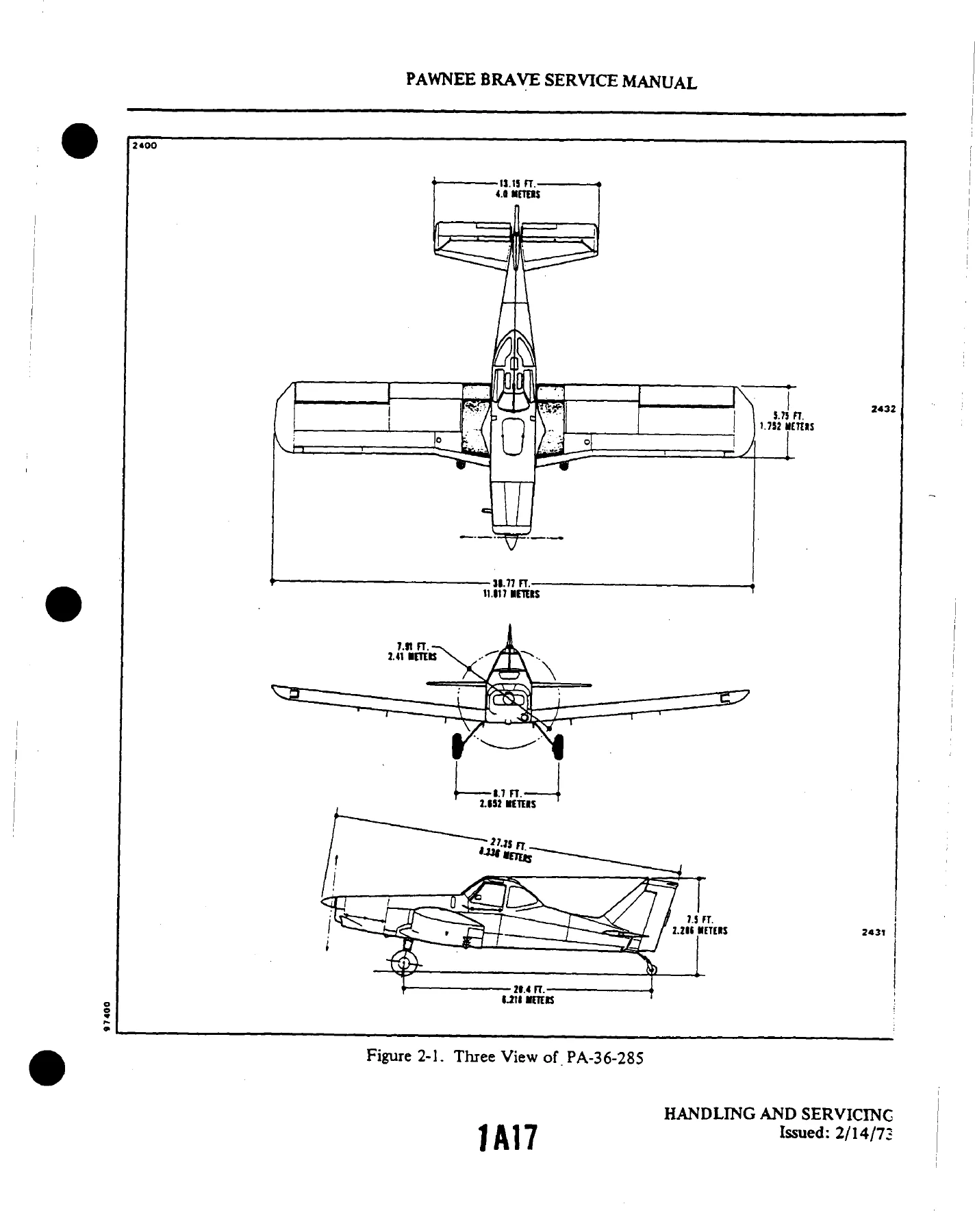
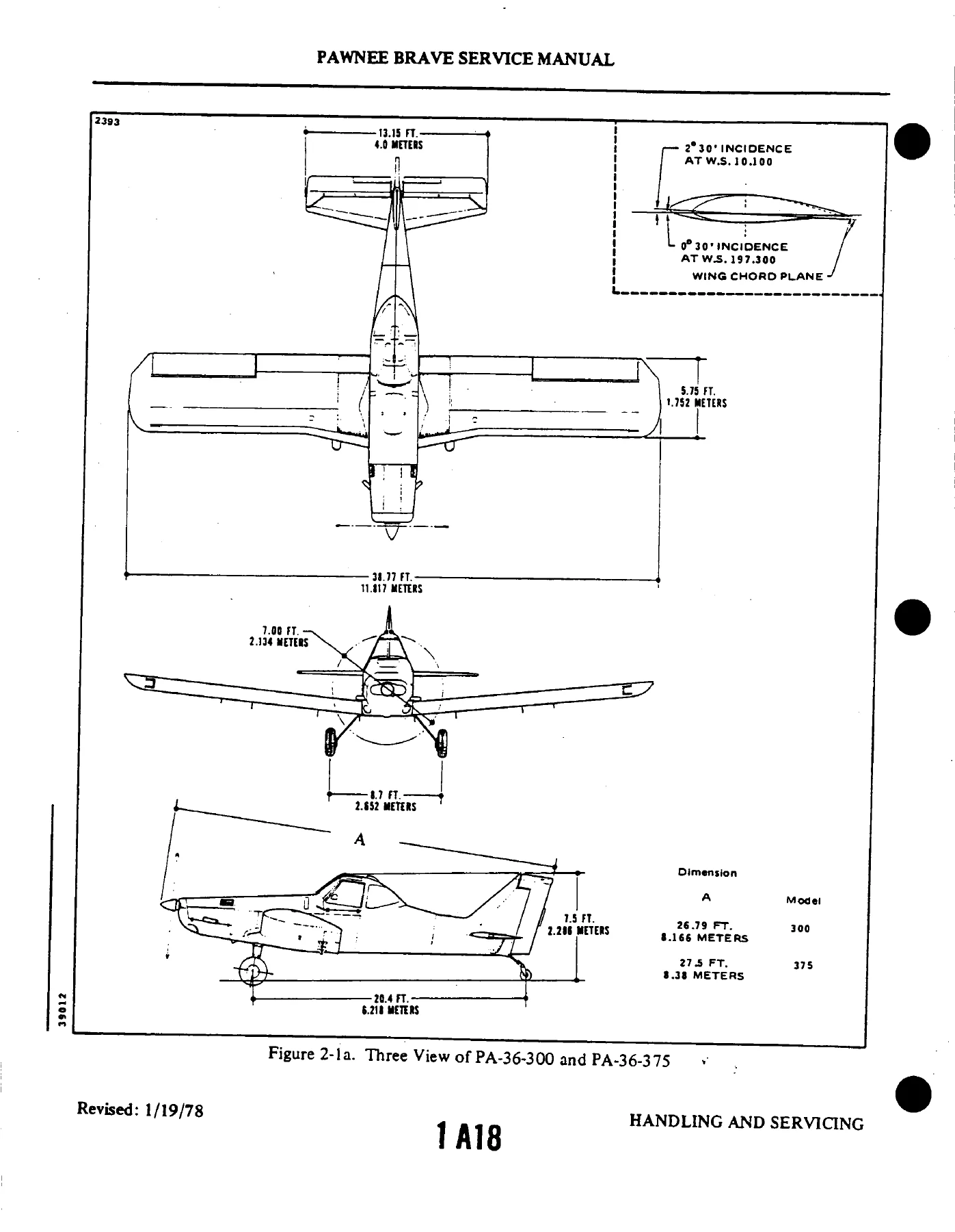
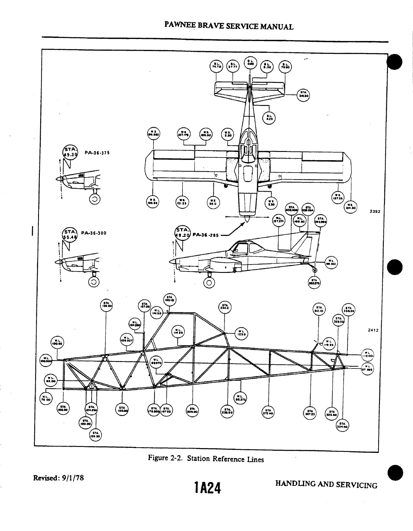
- II – Handling and Servicing: dimensions, station reference lines, weight and balance, access and inspection provisions, tools and test equipment, torque requirements, ground handling, jacking, lifting, leveling, weighing, servicing fuel, brake, tire, landing gear, propeller, electrical and battery systems, engine lubrication (Continental and Lycoming), cleaning, repainting, storage
- III – Inspection: inspection periods and requirements, preflight check, overlimits inspection, special inspections, exhaust system inspection (PA-36-285, -300 and -375), rod end bearing inspection, inspection report tables
- IV – Structures: service life limits, wing group, wing tip, leading edge, aileron, wing flap, wing removal and installation, empennage group, elevator, trim tab, horizontal stabilizer, rudder, vertical fin, fuselage assembly, windshield, windows, cabin doors, pilot seat, safety provisions, wire deflectors, structural repairs, fiberglass repairs, safety walk repair
- V – Surface Controls: control stick assembly, aileron controls, elevator controls, elevator trim controls, rudder controls, rudder pedal assemblies, wing flap controls, standard rigging procedures, balancing surface controls
- VI – Hydraulic System
- VII – Landing Gear and Brake System: main gear assembly, main wheel and axle assembly, main wheel assembly, wheel alignment, wheel balancing, tail gear assembly, tail wheel unit, brake system, wheel brake assembly, brake master cylinder (toe brake), parking brake valve, filling and bleeding brakes
- VIII – Power Plant (Continental): engine cowling, propeller and spinner, propeller governor, engine data, removal, cleaning, accessories, inspection, build-up, installation, flexible fluid hoses, engine baffles, engine mount, engine shock mounts, engine lubrication system, oil filter, oil pressure relief valve, oil cooler, induction air system, engine fuel system, throttle body, fuel manifold valve, fuel discharge nozzles, fuel injection pump, engine setup procedures, engine controls, ignition system, magneto, harness assembly, spark plugs, starting vibrator, extreme weather maintenance
- VIIIA – Power Plant (Lycoming 300): engine cowling, propeller and spinner, propeller governor, engine controls, induction air filter, alternate air door, fuel injector, fuel-air bleed nozzle, ignition system, magneto, harness assembly, spark plugs
- VIIIB – Power Plant (Lycoming 375): engine cowling, propeller and spinner, propeller governor, engine controls, induction air filter, alternate air door, fuel injector, fuel-air bleed nozzle, ignition system, magneto, harness assembly, spark plugs
- IX – Fuel System: fuel cells, polyurethane foam internal baffles, fuel quantity indicator system, fuel shutoff valve, fuel header tank, fuel filter, auxiliary fuel pump, auxiliary fuel control system (PA-36-285)
- X – Instruments: instrument panel, pitot and static system, sensitive altimeter, magnetic compass, airspeed indicator, turn coordinator, engine instruments, fuel quantity indicator, manifold pressure/fuel flow gauge, oil pressure/temperature/CHT combination gauge, tachometer, ammeter, clock, spray pressure gauge, stall warning system
- XI – Electrical System: alternator system and overhaul, battery, battery box, battery relay, voltage regulator, overvoltage control, starting motor, landing and taxi lights, night working lights, navigation lights, anti-collision strobe lights, rotating beacon, instrument lighting, stall warning horn and lift detector, switches and circuit breakers, auxiliary power receptacle, electrical schematics
- XII – Electronics: Emergency Locator Transmitter (Narco) description, location, battery, testing, inadvertent activation
- XIII – Environmental Control System: heating system, ventilation and ram air pressurization, ventilation air filter servicing
- XIV – Dispersal Systems: hopper assembly, liquid dispersal system, pump assemblies (wind driven and hydraulically driven), spray control valve, plumbing, strainer, boom assembly, nozzles, pressure gauge, quick loader system, spray system shutoff valve, dry material dispersal system, subtank gate control, agitator assembly, spreader assembly, windmill assembly modification
Put together, this Piper PA-36 Pawnee Brave service manual functions as the working reference for the whole airframe and both power plant families installed in the type. Structural chapters lay out the welded 4130 steel tube fuselage, the full cantilever wing with its two-bolt main spar attachment, the empennage and every removable skin and fairing, along with the fatigue-driven service life limits that govern spar fittings, carry-through assemblies and attachment bolts. Control chapters take the technician through rigging angles, cable tensions and static balance limits for ailerons, elevators and rudder. Landing gear material covers main and tail wheel assemblies, toe-in and camber alignment, wheel balancing and both the master cylinder and wheel brake cylinder rebuild sequences. Dispersal chapters cover the fiberglass hopper, spray boom, nozzles, subtank gate and dry material spreader, which is what makes this particular airframe so different from a standard utility aircraft. Power plant chapters are split three ways so the Continental 6-285 Tiara with its Vibratory Torque Control unit, the Lycoming IO-540 and the Lycoming IO-720 are each handled with their own cowling, fuel injection, ignition, magneto timing and control rigging procedures.
For anyone maintaining a Pawnee Brave, the practical value is in the details that factory training depends on: the exact torque values for wing attachment bolts and engine mount hardware, the fuel system pressure and flow values for both Continental and Lycoming injection, the magneto internal timing procedure with its painted-tooth and E-gap references, the alternator rotor resistance and output test figures, and the specific inspection intervals called out in the inspection report tables. Ag operators in particular will appreciate the dispersal system section, since the hopper, pump, boom and gate control work is covered to the same depth as the airframe itself.
Why This Manual Matters
Agricultural aircraft see some of the hardest service hours in general aviation. Between chemical exposure, dust, and short repetitive flights, Pawnee Brave airframes and engines accumulate wear fast, and guesswork is expensive. Having the correct rigging angles, the correct static balance limits, the correct torque values and the correct engine setup pressures in front of you is what separates a proper repair from one that comes back in fifty hours. The dispersal system sections matter just as much, because the pump, valves, booms and nozzles all interact and need to be set up as a matched system to spray evenly and consistently.
This Piper PA-36-285 PA-36-300 PA-36-375 Pawnee Brave service manual 761471 supports the full range of routine and corrective work: scheduled inspections, engine removal and installation, propeller and governor servicing, fuel cell and foam baffle maintenance, brake bleeding and master cylinder rebuilds, landing gear alignment, control surface balancing, harness lead repair and magneto timing. Whether you are chasing a rough-running IO-720, tracking down a leaking fuel cell, or just trying to work out how to rig the elevator trim tabs back to specification, the procedure and the numbers are here.
IMAGES PREVIEW
Delivered as an instant PDF download – no shipping, no waiting. Open it on any laptop, tablet or phone, print the pages you need for the hangar and keep the rest stored for the next job. Every page is scanned cleanly from the original aerofiche set, so the illustrations, exploded views and schematics come through clearly alongside the text.
Reviews
There are no reviews yet.