
Piper PA-30 PA-39 Twin Comanche Service Manual – Complete Aircraft Maintenance & Repair Guide
Original price was: $34.95.$19.95Current price is: $19.95.
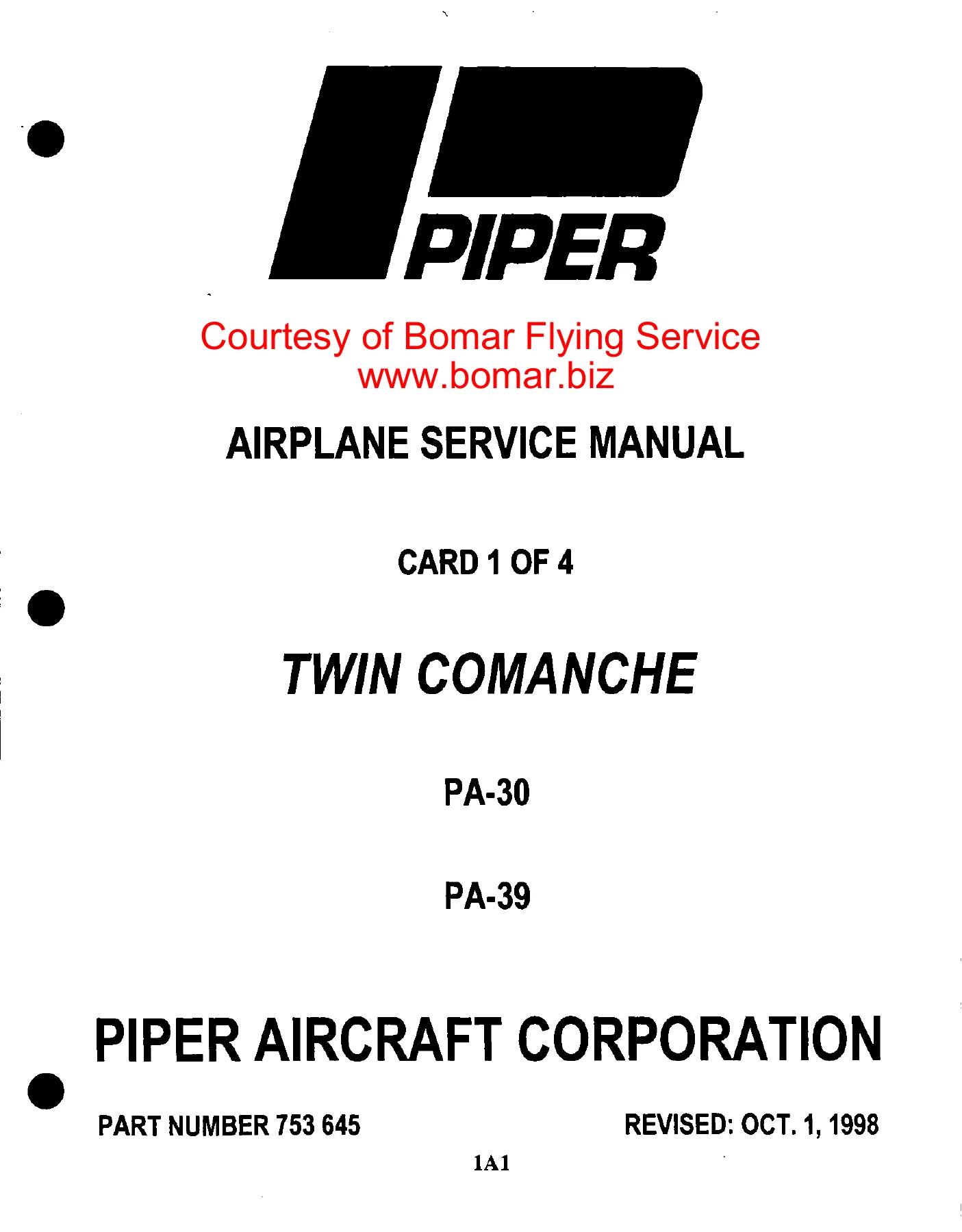
The complete Piper Twin Comanche service manual covering PA-30 and PA-39 models built from 1963 through 1972. Full airframe, engine, landing gear, fuel, electrical, heating and accessory coverage with illustrations, specifications and step-by-step procedures in a single PDF.
Description
Piper PA-30 & PA-39 Twin Comanche Service Manual
This is the complete Piper Twin Comanche service manual used by owners, A&P mechanics and restoration shops to maintain, inspect, troubleshoot and repair every major system on the PA-30 and PA-39 Twin Comanche. It covers both normally aspirated and turbocharged airframes and both engine families fitted to these aircraft across the full 1963 to 1972 production run. Whether you are chasing an intermittent landing gear fault, rigging controls after a rebuild, timing magnetos or resolving a fuel injector problem, the answers are here in the same wording and specification values the manual was written with.
File Details
- Manual type: Airplane Service Manual (workshop / maintenance)
- Brand / manufacturer: Piper Aircraft Corporation
- Models covered: PA-30 Twin Comanche, PA-39 Twin Comanche C/R
- Piper part number: 753 645
- Original publication: August 1, 1963
- Revision status: 8th revision, October 1, 1998 (issued in four aerofiche cards)
- Language: English
- File format: PDF
Chapters Covered
The service manual is organised into sections covering general information common to both models, followed by Part II which holds PA-39-specific material. The full contents are laid out as follows:
- Introduction – general description of fuselage, wing, empennage, flight controls, landing gear, brakes, engines and propellers, fuel system, instruments, electronics, heating and ventilating system
- Handling and Servicing – dimensions, station reference lines, weight and balance data, serial number plate, access and inspection provisions, tools and test equipment, torque requirements, torque wrenches, handholds and walkways, ground handling, jacking, weighing, leveling, mooring, parking, locking, towing, taxiing, external power receptacle, cleaning procedures
- Servicing – landing gear, oleo struts, brake system, tires, power plant, propeller, induction air filter, vacuum system air filters, fuel system, electrical system, oxygen system, lubrication, oil system, oil screens, oil filter, turbo oil filter, oil change recommendations, lubrication chart
- Inspection – inspection periods and requirements, definitions, preflight check, overlimits inspection, propeller group, engine group, turbocharger group, cabin group, fuselage and empennage group, wing group, landing gear group, operational and general inspections
- Structures – wing group, wing tip, landing light, aileron, flap, wing removal and installation, empennage, stabilator, stabilator trim tab, rudder, vertical fin, fuselage assembly, windshield, side windows, cabin door, door latch assembly, structural repairs, stabilator and stabilator tab repair, rudder repair, checking and balancing control surfaces, fiberglass repairs, thermoplastic repairs, safety walk repair, flow strips
- Surface Controls – control column assembly, aileron controls, aileron bellcrank, rigging and adjustment of aileron controls, aileron trim, stabilator controls, stabilator torque tube, rigging and adjustment of stabilator controls, stabilator trim controls, trim indicator, rudder and steering pedal assembly, rudder controls, rudder horn, rigging and adjustment of rudder controls, rudder trim controls, trim drum, wrapping trim drum, wing flap controls, flap transmission, flap control cables, flap bellcrank, step lock assembly, rigging and adjustment of flaps, checking flap indicating system, rigging and adjustment of flap position sender
- Appendix I – Control cable inspection procedure, external cable wear patterns, internal cable wear, pulley wear patterns
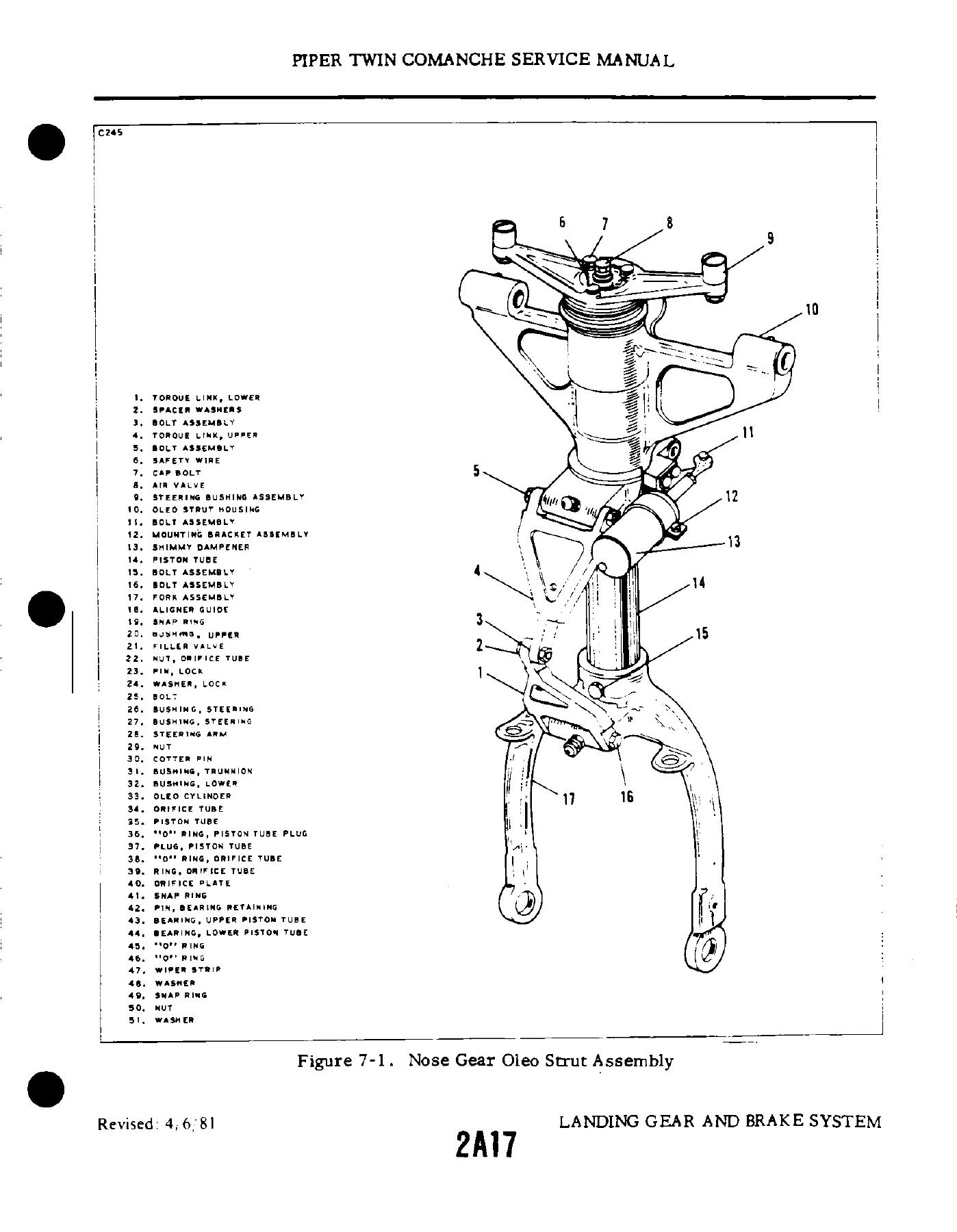
- Landing Gear and Brake System – nose landing gear, disassembly of nose gear oleo, cleaning and inspection, assembly, removal and installation of nose landing gear, adjustment of drag links, alignment, nose gear door assembly, main landing gear system, disassembly of main gear oleo, cleaning and inspection, assembly, removal and installation, inspection of main gear side brace links, adjustment of main gear side brace links, alignment of main gear, gear door assembly, wiper strip replacement, landing gear retraction system, retraction transmission, push-pull controls, adjustment of retraction system, safety switch, down limit switch, retraction transmission assembly adjustment, main gear push-pull cable adjustment, nose gear push-pull rod adjustment, gear up switch adjustment, retraction load check, gear down safety lock, warning switch, wheels (nose and main), removal, inspection, assembly and installation, brake system, brake assembly, brake disc replacement, brake cylinder, bleeding procedure, inspection of landing gear manual retraction system
- Power Plant (Normally Aspirated) – standard practices, troubleshooting, engine cowling, cowl flap rigging, propeller, propeller governor, engine removal and installation, engine shock mounts, oil cooler installation, induction air filter, alternate air door, fuel injector, fuel air bleed nozzles, ignition system, magneto, harness assembly, spark plugs, lubrication system, oil pressure relief valve, oil screens and filters
- Power Plant (Turbocharged) – troubleshooting, engine cowling, propeller, propeller governor, engine removal and installation, engine mount protection, engine shock mounts, turbocharger, induction system air filter, alternate air door, exhaust system, ignition system, magneto timing, fuel injector, lubrication system
- Fuel System – fuel cells, main and auxiliary, tip tanks, fuel system schematics (PA-30 and PA-30 Turbo), fuel indicating system, sender units, gauges, wing schematic, fuel strainer, fuel selector valve, Weldon rotary fuel pump, solenoid valve, fabricated fuel quantity transmitter checking jig
- Instruments – instrument panel layouts by serial number group, vacuum system installation, EGT thermocouple installation
- Electrical System – generator wiring, sectional view of generator, dual regulators, current/voltage regulator, contact point cleaning, voltage regulator air gap and adjustment, cutout relay, current regulator checks, alternator wiring, exploded view of alternator, rectifier removal, slip ring, rotor tests, brush installation, internal wiring diagram, alternator paralleling, regulator diagrams (Prestolite and Lamar), testing and adjusting regulators, overvoltage control, no-load and stall-torque tests for starting motors, gear reduction starting motor, motor armature tests, electrical system components by serial number, strobe lights, navigation lights, landing lights, position lights, dome lights, instrument lights, stall warning, starter system, magneto switches, fuel pumps, fuel quantity indicators, landing gear motor and solenoid, landing gear warning, oil pressure warning, pitot heat, turn and bank indicator, windshield heat, tip tanks, ammeter, alternator systems (nonparalleling and paralleling)
- Electronics – Piper Automatic Locator Transmitter (ELT) testing, battery removal and installation (Narco), autopilot and flight director service references, Piper AFCS equipment
- Heating and Ventilating System – South Wind heater (serial 30-1 to 30-401), Janitrol heater (serial 30-402 and up), heater operation, safety limit switch, inspection, removal and installation, principles of operation, safety valve, lockout overheat switch, thermal fuse, cycling switch, fuel system, fuel control valve, combustion air system, ventilating air system, electrical system, flame detector switch, igniter, cycle of operation, running cycle, purging cycle, service, adjustments, troubleshooting, disassembly, repair, reassembly, testing, burn test
- Accessories and Utilities – oxygen system description, troubleshooting, safety precautions, inspection and overhaul time limits, testing for leaks, maintenance, cleaning operations, removal and installation of oxygen cylinder, regulator, filler valve, pressure gauge, outlets, purging oxygen system, cleaning face masks, engine synchrophaser description, system operating procedure, operational checks, troubleshooting, removal and installation of strobe sensor, pulse generator, computer assembly, glow lamps
- Part II – PA-39 specific material: introduction, handling and servicing, structures (checking and balancing stabilator for serial 39-1 to 39-155), surface controls (rigging and adjustment of stabilator controls, adjustment of interconnecting control cables, checking stabilator frictional resistance), power plant normally aspirated, power plant turbocharged, instruments, electrical system, electronics
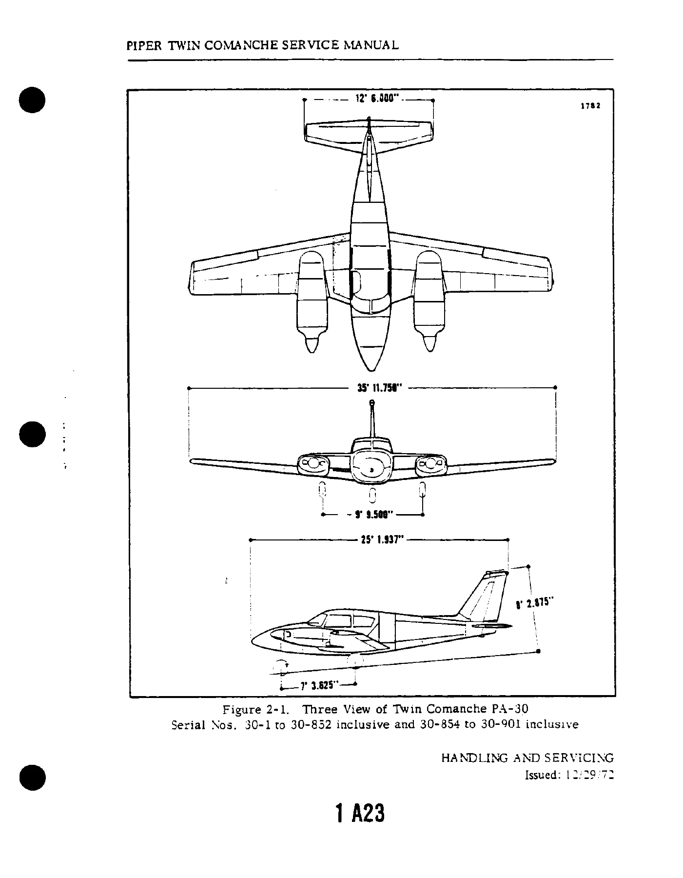
This Piper PA-30 PA-39 Twin Comanche service manual brings together what would otherwise be dozens of separate system documents into one continuous reference. Each system section is written in the same order a mechanic actually works through: troubleshooting and probable causes first, then removal, disassembly, cleaning and inspection, assembly, installation and rigging or adjustment. Torque values, cable tensions, control surface travel limits, strut extensions, wear limits and adjustment measurements appear inline with the procedures so there is no need to cross-reference. Serial-number groupings are used throughout so the correct variant-specific procedure is followed for the aircraft on the stand, and the illustrations – three-view dimension drawings, access panel maps, exploded component views, wiring and fluid-line schematics, lubrication chart diagrams – make the assemblies themselves easy to identify before any part is touched.
What You Can Do With This Manual
The manual supports the full scope of Twin Comanche ownership and maintenance work. Engine work from magneto timing and spark plug servicing through fuel injector removal and idle mixture adjustment is covered for both normally aspirated and turbocharged power plants. Airframe work includes control surface removal, installation, checking and balancing of the stabilator, rigging aileron, rudder and stabilator cables to the correct tension, and flap system adjustment with the flap position sender calibration. Landing gear and brake work runs from oleo strut servicing and wiper strip replacement through drag link adjustment, gear alignment, retraction system rigging, up and down limit switch adjustment, retraction load checking and complete brake bleeding. Fuel, electrical, heating and oxygen systems each carry their own troubleshooting chart listing probable causes and remedies, which is often the fastest way to isolate a fault before a component comes off the aircraft.
Why Having the Correct Procedures and Specifications Matters
Control surface balance, cable tension and control travel on the Twin Comanche are flight-safety items – guessing at them is not an option. The manual states the exact limits: aileron travel of 19 degrees up and 15 degrees down, stabilator travel of 9 degrees up and down, rudder travel of 27 degrees each side, flap deflection of 27 degrees, and cable tensions in pounds for each control circuit. It also gives the stabilator free play limit, rudder hinge moment, main and nose gear wear limits, oleo strut extensions, torque wrench correction formula for adapter use, and the flare fitting and nut torque tables by size and material. Working from the correct values the first time avoids repeat inspections, avoids damage caused by over- or under-torqued fasteners, and keeps the aircraft within the configuration it was certificated in.
IMAGES PREVIEW
Instant PDF Delivery
This Piper PA-30 PA-39 Twin Comanche Service Manual is delivered as an instant PDF download the moment your order completes – no shipping, no waiting on a physical book, no missing pages. It opens on any laptop, tablet or phone and every page can be printed at full size for use in the hangar or on the bench. Print a single section for the job in front of you, or keep the whole manual on a shop computer for quick reference across every system on the aircraft.
Reviews
There are no reviews yet.