Description
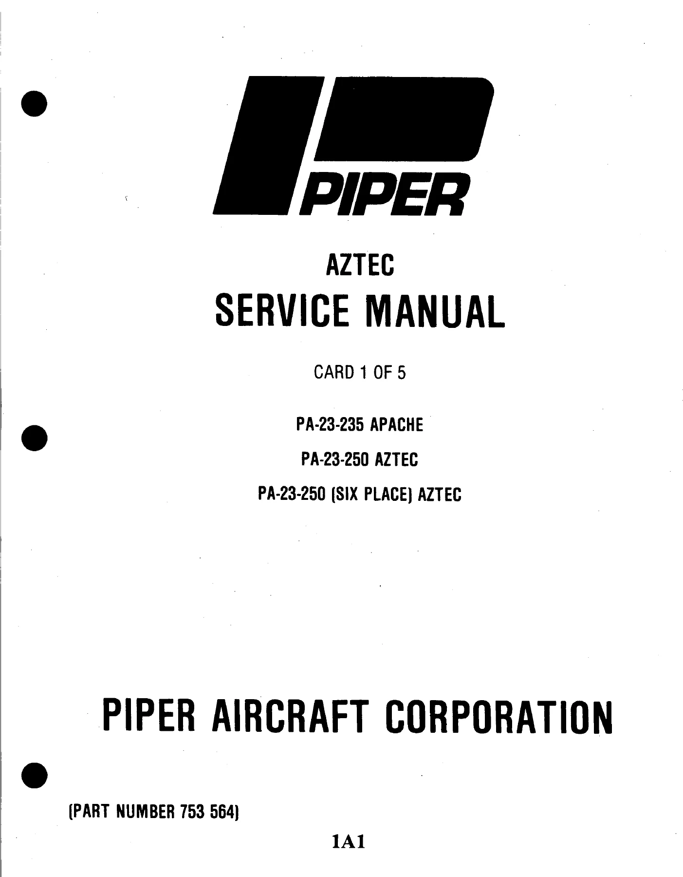
Complete Piper Aztec Service & Maintenance Manual
This is the official factory service manual for the Piper Aztec PA-23-235 and PA-23-250 series aircraft. It is an essential resource for aircraft mechanics, owners, and maintenance personnel working on these popular twin-engine aircraft. The manual is presented in a detailed, step-by-step format with extensive illustrations, exploded views, and wiring diagrams, making it the definitive source for information on the Aztec airframe and systems.
File Details
- Manual Type: Factory Service & Maintenance Manual
- Brand: Piper Aircraft Corporation
- Models Covered: PA-23-235 Apache, PA-23-250 Aztec, PA-23-250 (six place) Aztec
- Language: English
- Page Count: 1309 Pages (5 Aerofiche Cards)
- File Format: Digital PDF
- Part Number: 753 564
- Original Publication Date: November 11, 1972
- Revision Status: Includes revisions up to September 21, 1986
Chapters Covered
This manual covers every system and structure of the Piper Aztec. The content is organized into logical sections, each providing detailed instructions for inspection, servicing, removal, installation, and repair. Key chapters include:
- I. Introduction – General description of the aircraft and manual scope.
- II. Handling and Servicing – Dimensions, jacking, weighing, cleaning, standard practices, and servicing of all systems (hydraulic, landing gear, power plant, etc.).
- III. Inspection – Detailed 50, 100, 500, and 1000-hour inspection checklists, including preflight and special inspections.
- IV. Structures – Removal and installation of structural components (wing, empennage, fuselage), control surface balancing, and fiberglass/thermoplastic repair procedures.
- V. Surface Controls – Rigging and adjustment of aileron, stabilator, rudder, and flap control systems, including cable replacement and tensioning.
- VI. Hydraulic System – Complete overhaul, troubleshooting, and adjustment of the Powerpak, engine-driven pump, actuating cylinders, and related valves.
- VII. Landing Gear and Brake System – Full coverage of the retractable landing gear, oleo struts, wheel and brake assemblies, including alignment, adjustment, and servicing.
- VIII. Power Plant (Normally Aspirated) – Engine cowling, propeller, governor, engine removal/installation, carburetor, fuel injection, ignition system, and lubrication system maintenance for the Lycoming O-540 and IO-540 engines.
- VIIIA. Power Plant (Turbocharged) & VIIIB. Power Plant (Lycoming-Turbocharged) – Specific instructions for turbocharged AiResearch and Lycoming systems, including turbocharger removal, installation, and adjustment.
- IX. Fuel System – Servicing, removal, and installation of fuel cells, selector valves, filters, and electric fuel pumps, including system diagrams and troubleshooting.
- X. Instruments – Removal, installation, and adjustment of all flight and engine instruments, including vacuum and pitot-static systems.
- XI. Electrical System – Comprehensive schematics and troubleshooting for generators, alternators, regulators, starters, batteries, and all lighting circuits.
- XII. Electronics – Installation and testing of the Emergency Locator Transmitter (ELT).
- XIII. Heating and Ventilating System – Detailed information for South Wind and Janitrol heaters, including operation, troubleshooting, and overhaul.
- XIV. Accessories and Utilities – Oxygen system, propeller de-icers, pneumatic deicer system, and propeller synchronizer service and repair.
Complete PDF Bookmark Tree
Complete Bookmarks
The complete bookmarks in the “Piper Aztec Service Manual PA-23-235 & PA-23-250 | 1960-1986 | PDF Download” are as follows:
+PA-23-235 APACHE, PA-23-250 AZTEC, PA-23-25 (SIX PLACE) AZTEC PIPER PARTS CATALOGp. 1
+AEROFICHE CARD 1 OF 5p. 1
AEROFICHE EXPLANATION AND REVISION STATUSp. 2
TABLE OF CONTENTSp. 3
LIST OF ILLUSTRATIONSp. 5
LIST OF TABLESp. 18
+SECTION I INTRODUCTIONp. 21
+TABLE OF CONTENTSp. 21
Generalp. 22
Scope of Manualp. 22
Descriptionp. 22
Fuselagep. 22
Wingp. 23
Empennagep. 23
Flight Controlsp. 23
Hydraulic System.p. 23
Landing Gearp. 23
Engines and Propellersp. 23
Fuel Systemp. 25
Instrumentsp. 25
Electronic Equipmentp. 25
Heater and Ventilating Systemp. 25
+SECTION II HANDLING AND SERVICINGp. 26
+TABLE OF CONTENTSp. 26
Introductionp. 29
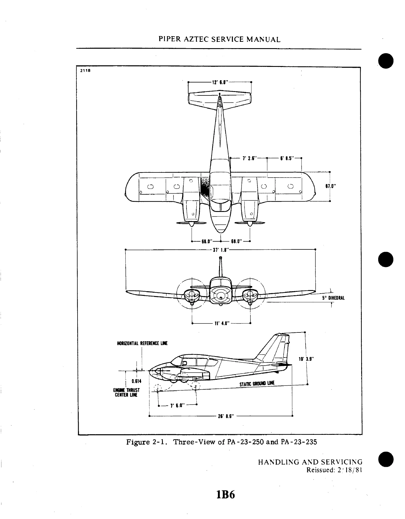
Dimensionsp. 29
Station Reference Linesp. 29
Weight and Balancep. 54
Serial Number Platep. 54
Access and Inspection Provisionsp. 54
Tools and Test Equipmentp. 54
Torque Requirementsp. 54
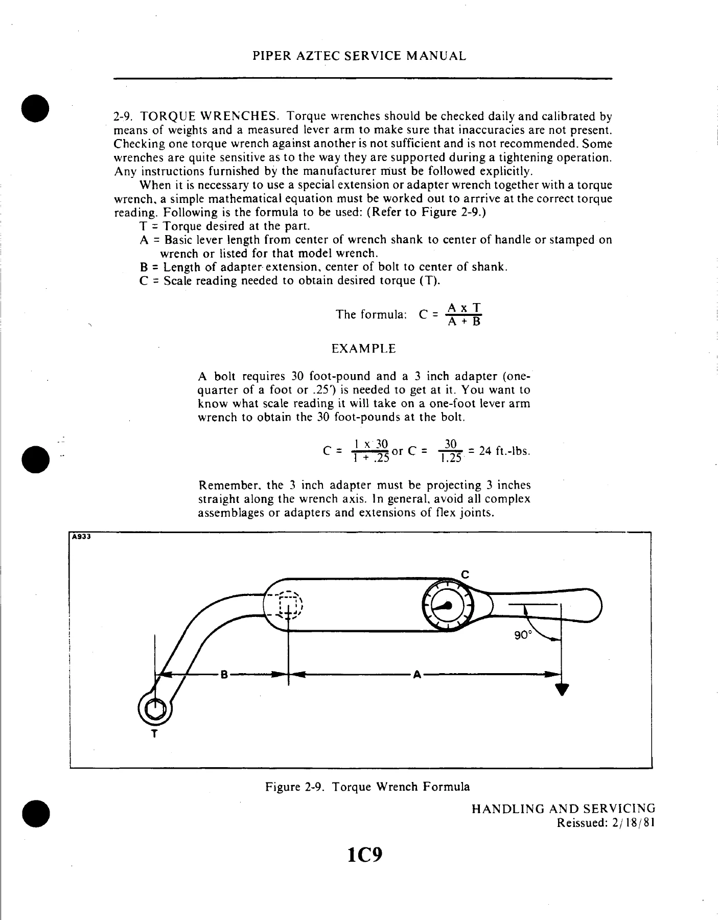
Torque Wrenchesp. 55
+Ground Handlingp. 67
Introduction to Ground Handlingp. 67
Jackingp. 67
Weighingp. 68
Levelingp. 69
Mooringp. 70
Parkingp. 70
Towingp. 71
Taxiingp. 71
+Hydraulic Systemp. 83
Servicing Hydraulic Systemp. 83
+External Power Receptaclep. 71
Operation of External Power Receptaclep. 71
+Cleaningp. 72
Cleaning Engine Compartmentp. 72
Cleaning Landing Gearp. 72
Cleaning Exterior Surfacesp. 73
Cleaning Windshield and Windowsp. 73
Cleaning Headliner, Side Panels and Seatsp. 73
Cleaning Carpetsp. 74
Repainting (Polythane Enamel)p. 74
Scratch Touch-up on Aluminum Surfacep. 74
Coating Procedure for New Aluminum Panel -Non- Alodizedp. 74
Coating Procedure for Alodized Aluminump. 74
Mixing Instructions for Primers and Topcoatsp. 75
V-48 Wash Primerp. 75
Epoxy Primerp. 75
Polytane 6351 Primerp. 75
Mixing Instructions for Polytane Enamelp. 76
Polytane Enamel all Colorsp. 76
+Standard Practices – Airframep. 77
Cherrylock Rivets, Removalp. 77
Identification of Fluid Linesp. 79
Flareless – Tube Assembliesp. 79
Support Clampsp. 82
+Servicingp. 83
Introduction to Servicingp. 83
+Powerpak Reservoirp. 84
Filling Powerpak Reservoir (Gravity)p. 84
Filling Powerpak Reservoir (Pressure)p. 88
+Landing Gear Systemp. 88
Servicing Landing Gearp. 88
+Oleo Strutsp. 89
Servicing Oleo Strutsp. 89
Adding Fluid to Strutsp. 90
Filling Oleo Strutsp. 90
Inflating Oleo Strutsp. 91
+Brake Systemp. 91
Servicing Brake Systemp. 91
Filling Brake Cylinder Reservoirp. 91
Draining Brake Systemp. 91
+Tiresp. 91
+Power Plantp. 92
Servicing Power Plantp. 92
+Induction Air Filterp. 92
Removal and Installation of Air Filter….p. 92
Service Instructionsp. 93
+Propellerp. 94
+Fuel Systemp. 95
Servicing Fuel Systemp. 95
Filling Fuel Cellsp. 95
Draining Moisture from Fuel Systemp. 95
Draining Fuel Systemp. 95
+Oxygen Systemp. 95
Servicing Oxygen Systemp. 95
Oxygen System Safety Precautionsp. 96
Filling Oxygen Cylinderp. 97
Lubricationp. 98
+Oil System (Engine)p. 98
Servicing Oil Systemp. 98
Draining Oil Sumpp. 98
Filling Oil Sumpp. 99
Oil Screen (Pressure)p. 99
Oil Filter. Full Flowp. 99
Oil Screen (Suction)p. 100
Recommendations for Changing Oilp. 100
Lubrication Instructionsp. 101
Application of Oilp. 101
Application of Greasep. 101
Lubrication Chartp. 102
+SECTION III INSPECTIONp. 117
+TABLE OF CONTENTSp. 117
Introductionp. 118
Recommended Lubricantsp. 118
+Inspection Periodsp. 118
Inspection Requirementsp. 118
Preflight Checkp. 119
Overlimits Inspectionp. 119
Special Inspectionsp. 120
Inspection of Flap Outboard Hingesp. 120
Inspection of Fuel Selector Control Cablesp. 120
+SECTION IV STRUCTURESp. 133
+TABLE OF CONTENTSp. 133
Introductionp. 137
Descriptionp. 137
+Wing Groupp. 138
Removal of Wing Tipp. 138
Installation of Wing Tipp. 141
+Aileronp. 141
Removal of Aileronp. 141
Installation of Aileronp. 141
+Flapp. 142
Removal of Flapp. 142
Installation of Flapp. 142
+Wingp. 142
Removal of Wingp. 142
Installation of Wingp. 145
Empennage Groupp. 150
+Stabilatorp. 150
Removal of Stabilatorp. 150
Installation of Stabilatorp. 151
Installation of New Stabilatorp. 151
+Stabilator Trim Tabp. 152
Removal of Stabilator Trim Tabp. 152
Installation of Stabilator Trim Tabp. 152
Stabilator Trim Tab Free Playp. 152
+Rudderp. 152
Removal of Rudderp. 152
Installation of Rudderp. 153
+Rudder Trim Tabp. 153
Removal of Rudder Trim Tabp. 153
Installation of Rudder Trim Tabp. 154
+Vertical Stabilizer (Fin)p. 154
Removal of Vertical Stabilizer (Fin)p. 154
Installation of Vertical Stabilizer (Fin) ..p. 157
Fuselage Assemblyp. 157
+Windshieldp. 157
Removal of Windshieldp. 157
Installation of Windshieldp. 161
+Side Windowsp. 161
Removal of Side Windows (PA-23-250, PA-23-235 and PA-23-250 [six place], Serial Nos. 27-2000 to 27-2504 incl.)p. 161
Installation of Side Windows (PA-23-250, PA-23-235 and PA-23-250 [six place], Serial Nos. 27-2000 to 27-2504 incl.)p. 162
Removal of Side Windows (PA-23-250 [six place], Serial Nos. 27-2505 and up)p. 162
Installation of Side Windows (PA-23-250 [six place], Serial Nos. 27-2505 and up)p. 163
+Emergency Exit (PA-23-250 [six place], Serial Nos. 27-2000 and up)p. 163
Removal of Emergency Exit Assemblyp. 163
Installation of Emergency Exit Assemblyp. 164
Removal of Emergency Exit Windowp. 164
Installation of Emergency Exit Windowp. 164
+Baggage Doorsp. 166
Removal of Aft Baggage Doorp. 166
Installation of Aft Baggage Doorp. 166
Removal of Aft Baggage Door Latch Assemblyp. 167
Installation of Aft Baggage Door Latchp. 167
Removal of Forward Baggage Door (PA-23-250 [six place])p. 168
Installation of Forward Baggage Door (PA-23-250 [six place])p. 168
Removal of Forward Baggage Door Latch (PA-23-250 [six place])p. 168
Installation of Baggage Door Latch (PA-23-250 [six place])p. 168
+Cabin Entrance Doorp. 169
Removal of Cabin Entrance Doorp. 169
Installation of Cabin Entrancep. 169
Adjustment of Cabin Entrance Doorp. 169
+Cabin Door Latch and Lock Assemblyp. 171
Removal of Cabin Door Latch and Lock Assemblyp. 171
Installation of Cabin Door Latch and Lock Assemblyp. 172
Structural Repairsp. 174
Checking Control Surface Balancep. 174
Balancing Stabilatorsp. 176
Balancing Ruddersp. 179
Balancing Aileronp. 181
+Fiberglass Repairsp. 182
Fiberglass Touch-Up and Surface Repairsp. 182
Fiberglass Fracture and Patch Repairsp. 183
Replacement of Damaged Nose Cone (PA-23-250, PA-23-235)p. 193
Replacement/ Installation of Nose Cone or Radome, (PA-23-250 [six place], Serial Nos. 27-4426, 27-4574 and up)p. 194
Thermoplastic Repairsp. 198
+Safety Walk Repairsp. 207
Surface Preparationp. 207
Product Listing for Liquid Safety Walk Compoundp. 207
Application of Liquid Safety Walk Compoundp. 207
Surface Preparation for Pressure Sensitive Safety Walkp. 208
Application of Pressure Sensitive Safety Walkp. 208
Shoulder Harness Inertia Reel Adjustmentp. 208
+SECTION V SURFACE CONTROLSp. 209
+TABLE OF CONTENTSp. 209
Introductionp. 212
Descriptionp. 212
Troubleshootingp. 216
Standard Proceduresp. 216
+Control Column Assemblyp. 216
Removal of Control Column Assembly Componentsp. 216
Installation of Control Column Assembly Componentsp. 218
+Aileron Controlsp. 220
Removal of Aileron Control Cablesp. 220
Installation of Aileron Control Cablesp. 225
Removal of Aileron Bellcrank Assemblyp. 226
Installation of Aileron Bellcrank Assemblyp. 227
Rigging and Adjustment of Aileron Controlsp. 227
Aileron Trimp. 230
+Stabilator Controlsp. 230
Removal of Stabilator Control Cablesp. 230
Installation of Stabilator Control Cablesp. 232
Rigging and Adjustment of Stabilator Controlsp. 239
+Stabilator Trimp. 241
Removal of Forward Stabilator Trim Assemblyp. 241
Installation of Forward Stabilator Trim Assemblyp. 242
Removal of Aft Stabilator Trim Assemblyp. 243
Installation of Aft Stabilator Trim Assemblyp. 243
Rigging and Adjustment of Stabilator Trimp. 244
Removal of Stabilator Trim Indicator Wire (PA-23-250, PA-23-235 and PA-23-250 (six place), Serial Nos. 27-2000 to 27-2504 incl.; and PA-23-250 (six place), Serial Nos. 27-2505 to 27-3836 incl., 27-3838 to 27-3943 incl.)p. 245
Installation of Stabilator Trim Indicator Wire (PA-23-250, PA-23-235 and PA-23-250 (six place), Serial Nos. 27-2000 to 27-250p. 246
Rigging and Adjustment of Stabilator Indicator Wire (PA-23-250, PA-23-235 and PA-23-250 (six place), Serial Nos. 27-2000 to 2p. 246
Removal of Stabilator Trim Indicator Wires PA-23-250 (six place), Serial Nos. 27-3837, 27-3944 and up)p. 247
Installation of Stabilator Trim Indicator Wire PA-23-250 (six place), Serial Nos. 27-2827, 27-3944 and up)p. 247
Adjustment of Stabilator Trim Indicator Wire PA-23-250 (six place), Serial Nos. 27-3837, 27-3944 and up)p. 248
+Rudder Controlsp. 251
Removal of Rudder Control Cablesp. 251
Installation of Rudder Control Cablesp. 251
Rigging and Adjustment of Rudder Controlsp. 252
+Rudder Trim Controlsp. 253
Removal of Forward Rudder Trim Assemblyp. 253
Installation of Forward Rudder Trim Assemblyp. 254
Removal of Aft Rudder Trim Assemblyp. 255
Installation of Aft Rudder Trim Assemblyp. 256
Rigging and Adjustment of Rudder Trimp. 256
Removal of Rudder Trim Indicator Wire (PA-23-250; PA-23-235 and PA-23-250 (six place), Serial Nos. 27-2000 to 27-2504 incl. ap. 257
Installation of Rudder Trim Indicator Wire (PA-23-250; PA-23-235 and PA-23-250 (six place), Serial Nos. 27-2000 to 27-2504 inp. 257
Rigging and Adjustment of Rudder Trim Indicator Wires (PA-23-250 (six place), Serial Nos. 27-2000 to 27-2504 incl. and PA-23-p. 258
Removal of Rudder Trim Indicator Wires PA-23-250 (six place), Serial Nos. 27-383 7, 27-3944 and up)p. 258
Installation of Rudder Trim Indicator Wire PA-23-250 (six place), Serial Nos. 27-3837, 27-3944 and up)p. 259
Adjustment of Rudder Trim Indicator Wire PA-23-250 (six place), Serial Nos. 27-3837, 27-3944 and up)p. 259
+Trim Drump. 260
+Wing Flap Controlsp. 261
Removal of Flap Actuator Assemblyp. 261
Installation of Flap Actuator Assemblyp. 261
Rigging and Adjustment of Flapsp. 263
Removal of Flap Position Senderp. 265
Installation of Flap Position Senderp. 265
Rigging and Adjustment of Flap Position Senderp. 265
+Stabilator Trim and Flap Interconnect System (Serial Nos. 27-7654001 and up)p. 266
Removal of Stabilator Trim and Flap Interconnect Systemp. 266
Installation of Stabilator Trim and Flap Interconnect Systemp. 266
Adjustment of Stabilator Trim and Flap Interconnect Systemp. 267
+Control System Friction Limitsp. 267
Friction in the Stabilator Control Systemp. 267
Friction in the Rudder Control Systemp. 267
Friction in the Aileron Control Systemp. 268
Adjustment of Stabliator Tab Position Indicatorp. 268
+AEROFICHE CARD 2 OF 5p. 283
AEROFICHE EXPLANATION AND REVISION STATUSp. 284
TABLE OF CONTENTSp. 285
LIST OF ILLUSTRATIONSp. 286
LIST OF TABLESp. 288
+SECTION VI HYDRAULIC SYSTEMp. 290
+TABLE OF CONTENTSp. 290
Introductionp. 296
Description and Principles of Operationp. 296
Troubleshootingp. 313
+Hydraulic Test Unitsp. 313
Hydraulic Test Unit (Piper No. 753 080)p. 313
Hydraulic Test Unit (Optional)p. 314
Connecting Hydraulic Test Unitp. 314
Disconnecting Hydraulic Test Unitp. 314
Cycling Landing Gearp. 315
Flushing Hydraulic Systemp. 316
+Hydraulic System Operation Checksp. 316
Pre-Check and General Instructionsp. 316
Checking Engine-Driven Hydraulic Pump Operationp. 318
Checking Powerpak Main Relief Valvep. 318
Checking Selector Lever Release to Neutralp. 324
+Internal Leakage Checksp. 325
Checking Hydraulic System for Internal Leaksp. 325
Checking Powerpak for Internal Leaksp. 326
Checking Hand Pump for Internal Leaksp. 328
Checking Components for Internal Leaksp. 329
Checking Anti-Retraction Valve for Internal Leaksp. 331
Checking Shuttle Valves for Internal Leaksp. 331
Checking Landing Gear Actuating Cylinders for Internal Leaksp. 332
Checking Timer Check Valve (Sequence Valve) for Internal Leaks (PA-23-250 [six place], Serial Nos. 27-2505 and up)p. 333
Checking Priority Valve for Internal Leaks (PA-23-250 [six place], Serial Nos. 27-2505 and up)p. 333
Checking Flap Actuating Cylinder for Internal Leaksp. 333
+Engine-Driven Hydraulic Pumpp. 334
Procedure After Engine-Driven Pump Failurep. 334
Removal of Engine-Driven Pumpp. 334
Disassembly of Engine-Driven Pumpp. 335
Cleaning, Inspection and Repair of Engine-Driven Pumpp. 336
Assembly of Engine-Driven Pumpp. 339
Installation of Engine-Driven Pumpp. 340
Priming Engine-Driven Pumpp. 340
Hydraulic System Failurep. 340
+Hydraulic Powerpakp. 341
Identification of Powerpakp. 341
Removal of Powerpakp. 341
Installation of Powerpakp. 343
+Overhaul of Powerpakp. 344
Overhaul Instructions and Precautionsp. 344
Special Tools and Test Equipmentp. 345
+Disassembly of Powerpakp. 351
Removal of Reservoir, Baffle and Platesp. 351
Removal and Disassembly of Main Relief Valvep. 352
Removal and Disassembly of Thermal Relief Valvep. 353
Removal of Camshaft Release Detent Assembliesp. 353
Removal of Poppets and Selector Camshaftsp. 354
Removal and Disassembly of Hand Pumpp. 356
Cleaning, Inspection and Repair of Powerpakp. 357
+Assembly of Powerpakp. 358
Assembly and Installation of Hand Pumpp. 358
Installation of Poppets and Selector Camshaftsp. 359
Installation of Camshaft Release Detent Assembliesp. 361
Assembly and Installation of Thermal Relief Valvesp. 362
Assembly and Installation of Main Relief Valvep. 362
Installation of Reservoir, Baffle and Platesp. 364
+Powerpak Bench Checks and Adjustmentsp. 364
Check and Adjustment Instructions and Precautionsp. 364
Powerpak Bleeding Procedurep. 366
Check and Adjustment of Main Relief Valvep. 366
Check and Adjustment of Thermal Relief Valvep. 367
Check and Adjustment of Camshaft Release Detent Assembliesp. 367
Check of Poppets for Leakagep. 369
Check of Hand Pumpp. 371
Final Check of Powerpakp. 371
Testing Reservoir for Leakagep. 373
+System Check Valvep. 374
Removal of Check Valvep. 374
Cleaning, Inspection and Overhaul of Check Valvep. 374
Testing Check Valvep. 375
Installation of Check Valvep. 375
+Anti-Retraction Valvep. 375
Removal of Anti-Retraction Valvep. 375
Disassembly of Anti-Retraction Valvep. 376
Cleaning, Inspection and Repair of Anti-Retraction Valvep. 376
Assembly of Anti-Retraction Valvep. 378
Testing Anti-Retraction Valvep. 378
Installation of Anti-Retraction Valvep. 378
Adjustment of Anti-Retraction Valvep. 380
+Shuttle Valvesp. 380
Removal of Shuttle Valvesp. 380
Cleaning, Inspection and Overhaul of Shuttle Valvep. 380
Testing Shuttle Valvep. 382
Installation of Shuttle Valvesp. 382
+Actuating Cylindersp. 383
Visual Check of Actuating Cylindersp. 383
+Gear and Flap Actuating Cylindersp. 383
Removal of Nose Gear Actuating Cylinderp. 383
Removal of Main Gear Actuating Cylinderp. 384
Removal of Flap Actuating Cylinderp. 384
Disassembly of Gear and Flap Actuating Cylindersp. 384
Cleaning, Inspection and Repair of Gear and Flap Actuating Cylindersp. 387
Assembly of Gear and Flap Actuating Cylindersp. 387
Installation of Nose and Main Gear Actuating Cylindersp. 387
Installation of Flap Actuating Cylinderp. 388
+Gear Door Actuating Cylinders (PA-23-250 [six place], Serial Nos. 27-2505 and up).p. 389
Removal of Nose and Main Gear Door Actuating Cylindersp. 389
Disassembly of Nose Gear Door Actuating Cylinderp. 389
Disassembly of Main Gear Door Actuating Cylinderp. 389
Cleaning, Inspection and Repair of Nose and Main Gear Door Actuating Cylindersp. 392
Assembly of Nose Gear Door Actuating Cylinderp. 392
Assembly of Main Gear Door Actuating Cylinderp. 392
Installation of Nose and Main Gear Door Actuating Cylindersp. 393
+Timer Check Valve (Sequence Valve) (PA-23-250 [six place], Serial Nos. 27-2505 and up)p. 393
Removal of Timer Check Valvep. 393
Disassembly of Timer Check Valvep. 393
Cleaning, Inspection and Repair of Timer Check Valvep. 395
Assembly of Timer Check Valvep. 395
Testing Timer Check Valvep. 395
Installation of Timer Check Valvep. 395
+Priority Valve (PA-23-250 [six place], Serial Nos. 27-2505 and up)p. 396
Removal of Priority Valvep. 396
Disassembly of Priority Valvep. 396
Cleaning, Inspection and Repair of Priority Valvep. 396
Assembly of Priority Valvep. 396
Testing and Adjustment of Priority Valvep. 398
Installation of Priority Valvep. 398
+Hydraulic Linesp. 398
Removal and Installation of Hydraulic Linesp. 399
+Hydraulic Filterp. 399
Removal and Installation of Hydraulic Filterp. 399
Replacement of Filter Elementp. 399
+Emergency Gear Extension System (Serial Nos. 27-1 to 27-7954121 incl.)p. 400
Description of Emergency Gear Extension Systemp. 400
Servicing Emergency Gear Extenderp. 400
Resetting Emergency Gear Extenderp. 400
Resetting Priority Valve, (PA-23-250 [six place], Serial Nos. 27-2505 and up )p. 401
Emergency Gear Extender Cable Riggingp. 401
Bypass Flow Valvep. 401
Bypass Flow Valve Testp. 401
Bypass Flow Valve Adjustmentp. 403
+SECTION VII LANDING GEAR AND BRAKE SYSTEMp. 424
+TABLE OF CONTENTSp. 424
Introductionp. 429
Descriptionp. 429
Troubleshootingp. 430
Landing Gear Systemp. 430
+Nose Landing Gear Systemp. 430
Disassembly of Nose Gear Oleop. 430
Cleaning, Inspection and Repair of Nose Gear Oleo……p. 433
Assembly of Nose Gear Oleop. 433
Removal of Nose Landing Gearp. 435
Cleaning, Inspection and Repair of Nose Landing Gearp. 435
Installation of Nose Landing Gearp. 437
Adjustment of Nose Landing Gearp. 438
Alignment of Nose Landing Gearp. 439
+Nose Gear Door Assemblyp. 443
Removal of Nose Gear Door Assembly (PA-23-250; PA-23-235; and PA-23-250 [six place], Serial Nos. 27-2000 to 27-2504 incl.)p. 443
Cleaning, Inspection and Repair of Nose Gear Door Assembly (PA-23-250; PA-23-235; and PA-23-250 [six place], Serial Nos. 27-2p. 443
Installation of Nose Gear Door Assembly (PA-23-250; PA-23-235; and PA-23-250 [six place], Serial Nos. 27-2000 to 27-2504 incl.)……………p. 443
Adjustment of Nose Landing Gear Doors (PA-23-250; PA-23-235; and PA-23-250 [six place], Serial Nos. 27-2000 to 27-2504 incl.)………………………………p. 444
Removal of Nose Gear Door Assembly (PA-23-250 [six place], Serial Nos. 27-2505 and up)p. 445
Cleaning, Inspection and Repair of Nose Gear Assembly (PA-23-250 [six place], Serial Nos. 27-2505 and up)p. 445
Installation of Nose Gear Door Assembly (PA-23-250 [six place], Serial Nos. 27-2505 and up)p. 445
Adjustment of Nose Landing Gear Doors (PA-23-250 [six place], Serial Nos. 27-2505 and up)p. 446
+Main Gear Assemblyp. 447
Disassembly of Main Gear Oleop. 447
Cleaning, Inspection and Repair of Main Gear Oleop. 450
Assembly of Main Gear Oleop. 450
Removal of Main Landing Gearp. 451
Cleaning, Inspection and Repair of Main Landing Gearp. 452
Installation of Main Landing Gearp. 454
Adjustment of Main Landing Gearp. 455
Alignment of Main Landing Gear Wheelp. 456
+Main Gear Door Assemblyp. 458
Removal of Main Gear Door and Actuator Assembly (PA-23-250, PA-23-235; and PA-23-250 [six place], Serial Nos. 27-2000 to 27-2p. 458
Cleaning, Inspection and Repair of Main Gear Door Assembly (PA-23-250, PA-23-235; and PA-23-250 [six place], Serial Nos. 27-2p. 458
Adjustment of Main Gear Doors (PA-23-250, PA-23-235; and PA-23-250 [six place], Serial Nos. 27-2000 to 27-2504 incl.)p. 459
Removal of Main Gear Door and Actuator Assembly (PA-23-250 [six place], Serial Nos. 27-2505 and up)p. 460
Cleaning, Inspection and Repair of Main Gear Door Assembly (PA-23-250 [six place], Serial Nos. 27-2505 and up)p. 462
Installation of Main Gear Door and Actuator Assembly (PA-23-250 [six place], Serial Nos. 27-2505 and up)p. 458
Adjustment of Main Landing Gear Doors (PA-23-250 [six place], Serial Nos. 27-2505 and up)p. 462
+Adjustment of Landing Gear Limit Switchesp. 464
Adjustment of Nose Gear Up Limit Switchp. 464
Adjustment of Main Gear Up Limit Switchp. 465
Adjustment of Landing Gear Down Limit Switchesp. 466
+Landing Gear Warning Systemp. 467
Removal of Gear Warning Switchesp. 467
Installation of Gear Warning Switchesp. 467
Adjusting Gear Warning Switchesp. 468
+Wheelsp. 469
Removal and Disassembly of Nose Wheelp. 469
Inspection of Nose Wheel Assemblyp. 470
Assembly and Installation of Nose Wheelp. 470
Removal and Disassembly of Main Wheelp. 471
Inspection of Main Wheel Assemblyp. 472
Repair of Main Wheel Assemblyp. 473
Assembly and Installation of Main Wheelp. 474
Brake Systemp. 475
+Wheel Brake Assemblyp. 475
Brake Adjustment and Lining Tolerancesp. 475
Removal and Disassembly of Wheel Brake Assemblyp. 475
Cleaning. Inspection and Repair of Wheel Brake Assemblyp. 475
Assembly and Installation of Wheel Brake Assemblyp. 480
+Brake Master Cylinderp. 480
Removal of Brake Master Cylinderp. 480
Disassembly of Brake Master Cylinderp. 481
Cleaning, Inspection and Repair of Brake Master Cylinderp. 481
Assembly of Brake Master Cylinderp. 482
Installation of Brake Master Cylinderp. 482
+Parking Brake Valvep. 484
Removal of Parking Brake Valvep. 484
Disassembly of Parking Brake Valvep. 484
Cleaning, Inspection and Repair of Parking Brake Valve..p. 484
Assembly of Parking Brake Valvep. 485
Installation of Parking Brake Valvep. 485
Bleeding Procedurep. 485
+Tire Balancingp. 487
Construction of Tire Balancerp. 487
+AEROFICHE CARD 3 OF 5p. 500
AEROFICHE EXPLANATION AND REVISION STATUSp. 501
TABLE OF CONTENTSp. 502
LIST OF ILLUSTRATIONSp. 503
LIST OF TABLESp. 506
+SECTION VIII POWER PLANT (NORMALLY ASPIRATED)p. 507
+TABLE OF CONTENTSp. 507
Introductionp. 510
Descriptionp. 510
Troubleshootingp. 511
Standard Practices – Enginep. 512
+Engine Cowlingp. 513
Removal of Engine Cowling. (PA-23-250; Serial Nos. 27-2000 to 27-2504 incl.)p. 513
Removal of Engine Cowlingp. 513
Cleaning, Inspection and Repair of Engine Cowlingp. 514
Installation of Engine Cowling. (PA-23-250; PA-23-235; and PA-23-250 (six place), Serial Nos. 27-2000 to 27-2504 incl.)p. 514
Installation of Engine Cowling. (PA-23-250 (six place), Serial Nos. 27-2505 and upp. 514
+Engine Cowl Flap. (PA-23-250 (six place), Serial Nos. 27-2505 and up.)p. 515
Removal of Cowl Flap Assemblyp. 515
Removal of Cowl Flap Control Cablep. 515
Installation of Cowl Flap Control Cablep. 516
Installation of Cowl Flap Assemblyp. 516
Rigging and Adjusting Engine Cowl Flapsp. 518
+Propellerp. 519
Removal of Propeller. (PA-23-250; PA-23-235; and PA-23-250 (six place), Serial Nos. 27-2000 to 27-2504 incl.)p. 519
Cleaning, Inspection and Repair of Propellerp. 520
Installation of Propeller. (PA-23-250; PA-23-23 5; and PA-23-250 (six place), Serial Nos. 27-2000 to 27-2504 incl.)p. 521
Removal of Propeller, PA-23-250 (six place), Serial Nos. 27-2505 and upp. 523
Cleaning, Inspection and Repair of Propellerp. 526
Installation of Propeller, PA-23-250 (six place), Serial Nos. 27-2505 and upp. 527
Adjustment of Low Pitch Blade Angle and Stop, PA-23-250; PA-23-235 and PA-23-250 (six place), Serial Nos. 27-2000 to 27-2504 incl.p. 528
Adjustment of Low Pitch Blade Angle and Stop, Serial Nos. 27-2505 and upp. 528
Blade Trackp. 530
+Propeller Governorp. 530
Removal of Propeller Governorp. 530
Installation of Propeller Governorp. 530
Rigging and Adjustment of Propeller Governorp. 531
+Enginep. 533
Removal of Engine, PA-23-250; PA-23-235 and PA-23-250 (six place), Serial Nos. 27-2000 to 27-2504 inclp. 533
Installation of Engine, PA-23-250; PA-23-235; and PA-23-250 (six place), Serial Nos. 27-2000 to 27-2504 incl.p. 537
Removal of Engine, PA-23-250 (six place), Serial Nos. 27-2372 and upp. 538
Installation of Engine, PA-23-250 (six place), Serial Nos. 27-2505 and upp. 539
+Engine Shock Mountsp. 543
Replacing Engine Shock Mountsp. 543
+Carburetor, PA-23-250; PA-23-235 and PA-23-250 (six place), Serial Nos. 27-2000 to 27-2504 incl.p. 544
Carburetor Maintenancep. 544
Removal of Carburetorp. 545
Installation of Carburetorp. 545
Adjustment of Throttle and Mixture Controlsp. 545
Adjustment of Idle Mixturep. 546
Adjustment of Engine Idling Speedp. 547
+Fuel Injector, PA-23-250 (six place), Serial Nos. 27-2322 and upp. 547
Fuel Injector Maintenancep. 547
Lubrication of Fuel Injectorp. 549
Removal of Fuel Injectorp. 549
Preparation for Storagep. 549
Installation of Fuel Injectorp. 550
Adjustment of Throttle and Mixture Controlsp. 551
Adjustment of Idle Speed and Mixturep. 551
+Fuel Air Bleed Nozzlep. 553
Removal of Fuel Air Bleed Nozzlep. 553
Cleaning and Inspection of Fuel Air Bleed Nozzlep. 553
Installation of Fuel Air Bleed Nozzlep. 553
+Magnetop. 554
Inspection of Magnetosp. 554
Removal of Magnetop. 556
Timing Procedure (Internal Timing)p. 557
Installation and Timing Procedure (Timing Magneto to Engine)p. 560
+Harness Assemblyp. 562
Inspection of Harnessp. 562
Removal of Harnessp. 562
Installation of Harnessp. 563
+Spark Plugsp. 563
Removal of Spark Plugsp. 563
Inspection and Cleaning of Spark Plugp. 565
Installation of Spark Plugsp. 566
+Starting Vibrator (14 and 28-Volt System)p. 566
Starting Vibrator Checking Procedurep. 566
Removal of Starting Vibratorp. 567
Installation of Starting Vibratorp. 567
+Lubrication Systemp. 568
Adjustment of Oil Pressure Relief Valvep. 568
Installation of Oil Coolerp. 568
Checks and Adjustments of Ball Joint Exhaust Systemsp. 569
+SECTION VIIIA POWER PLANT (TURBOCHARGED)p. 587
+TABLE OF CONTENTSp. 587
Introductionp. 590
Descriptionp. 590
Troubleshootingp. 592
Standard Practices – Engine (See Section VIII)p. 592
+Engine Cowlingp. 592
Removal of Engine Cowlingp. 592
Cleaning, Inspection and Repairp. 593
Installation of Engine Cowlingp. 593
+Engine Cowl Flapp. 593
Removal of Cowl Flap Assemblyp. 593
Removal of Cowl Flap Control Cablep. 595
Installation of Cowl Flap Control Cablep. 595
Installation of Cowl Flap Assemblyp. 596
Rigging and Adjusting Engine Cowl Flapsp. 596
+Propellerp. 596
Removal of Propellerp. 596
Cleaning, Inspection and Repair of Propellerp. 599
Installation of Propellerp. 601
Adjustment of Low Pitch Blade Angle and Stopp. 602
Blade Trackp. 603
+Propeller Governorp. 604
Removal of Propeller Governorp. 604
Installation of Propeller Governorp. 604
Rigging and Adjustment of Propeller Governorp. 605
+Enginep. 606
Removal of Enginep. 606
Installation of Enginep. 607
+Engine Shock Mountsp. 610
Replacing Engine Shock Mountsp. 610
+Fuel Injectorp. 611
Fuel Injector Maintenancep. 612
Lubricationp. 612
Removal of Fuel Injector, Nozzle Lines, Fuel Lines and Fuel Flow Dividerp. 612
Preparation for Storagep. 614
Installation of Fuel Injectorp. 615
Adjustment of Throttle and Mixture Controlsp. 616
Adjustment of Idle Speed and Mixturep. 616
+Fuel Air Bleed Nozzlep. 617
Removal of Fuel Air Bleed Nozzlep. 617
Cleaning and Inspection of Fuel Air Bleed Nozzlep. 617
Installation of Fuel Air Bleed Nozzlep. 618
Ignition System Maintenancep. 618
+Magnetop. 618
Inspection of Magnetop. 618
Removal of Magnetop. 620
Timing Procedure (Internal Timing) (-1200 series magnetos)p. 621
Installation and Timing Procedure. (Timing Magneto to Engine.)p. 624
+Harness Assemblyp. 626
Inspection of Harnessp. 626
Removal of Harnessp. 626
Maintenance of Harnessp. 627
Installation of Harnessp. 632
+Spark Plugsp. 634
Removal of Spark Plugsp. 634
Inspection and Cleaning of Spark Plugp. 635
Installation of Spark Plugsp. 636
+Starting Vibrator (14 and 28-Volt System)p. 636
Starting Vibrator Checking Procedure.p. 636
Removal of Starting Vibratorp. 637
Installation of Starting Vibratorp. 637
+Lubrication Systemp. 638
Adjustment of Oil Pressure Relief Valvep. 638
Installation of Oil Coolerp. 638
+Turbocharger (AiResearch)p. 641
Specificationsp. 641
Nomenclaturep. 642
Removal and Installation of Turbochargerp. 644
Removal of Turbochargerp. 645
Removal of Compressor Housingp. 645
Installation of Turbochargerp. 646
Removal of Turbocharger Oil Pumpp. 647
Installation of Turbocharger Oil Pumpp. 648
Transfer Valve Purpose and Functionp. 649
Checking Transfer Valve for Leaksp. 649
Adjustment of Transfer Valvep. 650
Adjustment of Automatic System Controllerp. 650
Cleaning or Replacing Turbo Oil Filter Elementp. 652
+SECTION VIIIB POWER PLANT (LYCOMING-TURBOCHARGED)p. 669
+TABLE OF CONTENTSp. 669
Introductionp. 671
Descriptionp. 671
Troubleshootingp. 673
Standard Practices – Engine (See Section VIII)p. 673
+Engine Cowlingp. 673
Removal of Engine Cowlingp. 673
+Engine Cowl Flapp. 673
Removal of Cowl Flap Mechanism Assemblyp. 673
Removal of Cowl Flap Control Cablep. 675
Installation of Cowl Flap Control Cablep. 676
Installation of Cowl Flap Mechanism Assemblyp. 676
Rigging and Adjustment of Cowl Flapsp. 677
+Enginep. 678
Removal of Enginep. 678
Installation of Enginep. 681
+Turbocharger (Lycoming)p. 683
Removal of Turbochargerp. 683
Removal of the Controller Housingp. 685
Removal of Exhaust Bypass Valve Assemblyp. 685
Turbocharger Lubrication System Primingp. 685
Installation of Turbocahrgerp. 686
Installation of the Controller Housingp. 686
Installation of Exhaust Bypass Valve Assemblyp. 686
Adjustment of Turbochargerp. 687
+Fuel Injectorp. 687
Removal of Fuel Injector, Lines and Flow Dividerp. 687
Installation of Fuel Injectorp. 687
+Propellerp. 596
Removal of Propellerp. 596
Cleaning, Inspection and Repair of Propellerp. 599
Installation of Propellerp. 601
Adjustment of Low Pitch Blade Angle and Stopp. 602
Blade Trackp. 603
+Propeller Governorp. 604
Removal of Propeller Governorp. 604
Installation of Propeller Governorp. 604
Rigging and Adjustment of Propeller Governorp. 605
+Enginep. 606
Removal of Enginep. 606
Installation of Enginep. 607
+Engine Shock Mountsp. 610
Replacing Engine Shock Mountsp. 610
+Fuel Injectorp. 611
Fuel Injector Maintenancep. 612
Lubricationp. 612
Removal of Fuel Injectorp. 612
Preparation for Storagep. 614
Installation of Fuel Injectorp. 615
Adjustment of Throttle and Mixture Controlsp. 616
Adjustment of Idle Speed and Mixturep. 616
+Fuel Air Bleed Nozzlep. 617
Removal of Fuel Air Bleed Nozzlep. 617
Cleaning and Inspection of Fuel Air Bleed Nozzlep. 617
Installation of Fuel Air Bleed Nozzlep. 618
Ignition System Maintenancep. 618
+Magnetop. 618
Inspection of Magnetop. 618
Removal of Magnetop. 620
Timing Procedure (Internal Timing) (-1200 series magnetos)p. 621
Installation and Timing Procedure (Timing Magneto to Engine)p. 624
+Harness Assemblyp. 626
Inspection of Harnessp. 626
Removal of Harnessp. 626
Maintenance of Harnessp. 627
Installation of Harnessp. 632
+Spark Plugsp. 634
Removal of Spark Plugsp. 634
Inspection and Cleaning of Spark Plugsp. 635
Installation of Spark Plugsp. 636
+Starting Vibrator (14 & 28-Volt System)p. 636
Starting Vibrator Checking Procedurep. 636
Removal of Starting Vibratorp. 637
Installation of Starting Vibratorp. 637
+Lubrication Systemp. 638
Adjustment of Oil Pressure Relief Valvep. 638
Installation of Oil Coolerp. 638
+SECTION IX FUEL SYSTEMp. 698
+TABLE OF CONTENTSp. 698
Introductionp. 701
Descriptionp. 701
Troubleshootingp. 709
+Fuel Cellsp. 709
Removal of Fuel Cellsp. 709
Removal of Wing Tip Fuel Cellp. 710
Cleaning, Inspection and Repair of Fuel Cellsp. 710
Fuel Cell Compartmentp. 713
Resealing Inboard Fuel Cell Wing Cavity Areap. 713
Molded Nipple Fittingsp. 716
Installation of Fuel Cellp. 716
Installation of Wing Tip Fuel Cellp. 717
Handling and Storage of Fuel Cellsp. 718
+Repair of Fuel Cellp. 718
+Fuel Quantity Indicating Systemp. 721
Checking Fuel Quantity Indicating Systemp. 721
Removal and Installation of Wing Fuel Sight Gaugep. 724
Removal of Fuel Senderp. 724
Installation of Fuel Senderp. 725
+Fuel Selector Valves (PA-23-250; and PA-23-250 (six place), Serial Nos. 27-2000 to 27-2222 incl.)p. 725
Removal of Fuel Selector Valvep. 725
Disassembly of Fuel Selector Valvep. 725
Cleaning, Inspection and Repair of Fuel Selector Valvep. 726
Assembly of Fuel Selector Valve.p. 726
Leak Test of Fuel Selector Valvep. 726
Installation of Fuel Selector Valvep. 727
Adjustment of Fuel Shutoff Valve Controlsp. 728
+Fuel Selector Valve (Three-way valve) (PA-23-235; and PA-23-250 (six place), Serial Nos. 27-2223 and up)p. 728
Removal of Fuel Selector Valvep. 729
Disassembly of Fuel Selector Valvep. 729
Cleaning, Inspection and Repair of Fuel Selector Valvep. 729
Assembly of Fuel Valvep. 730
Leak Test of Selector Valvep. 730
Installation of Fuel Selector Valvep. 731
Adjustment of Fuel Selector Valvep. 732
+Fuel Selector Valve (Three-Way Valve) (PA-23-235; PA-E23-250; and PA-23-250) (six place) (Dukes P/N 3564-00-1, -2)p. 732
Removal of Fuel Selector Valvep. 732
Inspection and Leak Test of Fuel Selector Valvep. 733
Installation of Fuel Selector Valvep. 735
Adjustment and Lubrication of Fuel Selector Valvep. 736
+Fuel Selector Valve Control Cables (Earlier)p. 737
Removal of Fuel Selector Valve Control Cablesp. 737
Installation of Fuel Selector Valve Control Cablesp. 737
+Fuel Selector Valve Control Cables (Later)p. 738
Removal of Fuel Selector Control Valve Cablesp. 738
Installation of Fuel Selector Control Valve Cablesp. 739
+Fuel Crossfeed Valvep. 740
Removal of Crossfeed Valvep. 740
Disassembly of Fuel Crossfeed Valvep. 740
Cleaning, Inspection and Repair of Fuel Crossfeed Valvep. 741
Assembly of Fuel Crossfeed Valvep. 741
Leak Test of Crossfeed Valvep. 741
Installation of Fuel Crossfeed Valvep. 742
+Fuel Filterp. 742
Removal of Fuel Filterp. 742
Disassembly, Inspection and Assembly of Fuel Filterp. 743
Disassembly of Fuel Filter Assemblyp. 743
Cleaning, Inspection and Repair of Fuel Pumpp. 744
Assembly of Fuel Filterp. 744
Installation of Fuel Filterp. 745
Electric Fuel Pumpsp. 745
+Plunger Fuel Pumps (Bendix) (PA-23-250; PA-23-235; and PA-23-250 (six place), Serial Nos. 27-2000 to 27-2504 incl.)p. 745
Removal of Fuel Pumpp. 745
Disassembly of Fuel Pumpp. 745
Cleaning, Inspection and Repair of Fuel Pumpp. 747
Resistance Check (Plunger Type Pump)p. 747
Assembly of Fuel Pumpp. 747
Installation of Fuel Pumpp. 749
Adjustment of Electric Fuel Pump (Bench Test)p. 749
Adjustment of Electric Fuel Pump (In Airplane)p. 749
+Rotary Fuel Pumps (Weldon) (PA-23-250 – six place, Serial Nos. 27-2322 and up)p. 750
Removal of Fuel Pumpsp. 750
Disassembly of Fuel Pumpp. 750
Inspection and Repairp. 752
Assembly of Fuel Pumpp. 753
Installation of Fuel Pumpp. 755
Adjustment of Electric Fuel Pump (Bench Test)p. 755
Adjustment of Electric Fuel Pump (In Airplane)p. 756
+Engine Primer Pumpp. 756
Removal of Engine Primerp. 756
Disassembly, Cleaning and Assembly of Engine Primerp. 756
Installation of Engine Primer Pumpp. 757
Prime Jetsp. 757
Cleaning Fuel Systemp. 758
+AEROFICHE CARD 4 OF 5p. 766
AEROFICHE EXPLANATION AND REVISION STATUSp. 767
TABLE OF CONTENTSp. 768
LIST OF ILLUSTRATIONSp. 769
LIST OF TABLESp. 772
+SECTION X INSTRUMENTSp. 773
+TABLE OF CONTENTSp. 773
Introductionp. 775
Descriptionp. 775
+Instrumentsp. 785
Vacuum-Gyro Instrumentsp. 785
Pitot-Static Instrumentsp. 785
Electrical Instrumentp. 786
Miscellaneous Instrumentsp. 787
+Troubleshootingp. 787
Removal of Instruments (PA-23-250; PA-23-23 5; PA-23-250 (six place), Serial Nos. 27-2000 to 27-2504 incl.; and PA-23-250 (sip. 787
Installation of Instruments (PA-23-250; PA-23-235; PA-23-250 (six place), Serial Nos. 27-2000 to 27-2504 incl; and PA-23-250p. 788
Removal of Instruments (PA-23-250 (six place), Serial Nos. 27-3837, 27-3944 and up)p. 788
Installation of Instruments (PA-23-250 (six place), Serial Nos. 27-3837 27-3944 and up)p. 789
Gyro Service Procedurep. 789
Gyro Installation Inspectionp. 789
Gyro Handling and Shippingp. 789
Gyro Vacuum System (Three Relief Valve System) (PA-23-250, Serial Nos. 27-1 to 27-443 incl.)p. 790
Description of Operationp. 790
Adjustment of Vacuum Regulator and Relief Valvesp. 791
+Gyro Vacuum System (Two Relief Valve System) (PA-23-250, Serial Nos. 27-444 and up; PA-23-235; PA-23-250 (six place), Serial Nos. 27-2505 and upp. 793
Description of Operationp. 793
Adjustment of Vacuum Regulator and Relief Valvesp. 795
+Vacuum Test Selector Valve (PA-23-250, PA-23-235 and PA-23-250 (six place), Serial Nos. 27-2000 to 27-2504 inclp. 799
Removal of Vacuum Test Selector Valvep. 799
Installation of Vacuum Test Selector Valvep. 799
Manifold Pressure Gauge Filters (Turbocharger Installation Only)p. 799
Exhaust Gas Temperature Gaugep. 800
Removal of EGT Probe and Gaugep. 800
Cleaning and Inspectionp. 800
Installation of EGT Probe and Gaugep. 800
+SECTION XI ELECTRICALp. 814
+TABLE OF CONTENTSp. 814
Introductionp. 823
Descriptionp. 823
Troubleshootingp. 824
+Generator System (Delco-Remy)p. 824
Description of Generator Systemp. 824
Description of Generator Paralleling Systemp. 824
Checking Generator Systemp. 826
Adjustments, Tests and Maintenance of Generator Systemp. 827
Test and Maintenance of Generator (Delco-Remy)p. 828
Inspection of Generatorp. 828
Shunt Generator Outputp. 829
Checking Defective Generatorsp. 830
No Outputp. 830
Unsteady or Low Outputp. 832
Excessive Outputp. 832
Noisy Generatorp. 833
Disassembly, Repair and Reassemblyp. 833
Field Coil Removalp. 833
Inspection and Repairof Partsp. 834
Field Coil Servicep. 834
Armature Servicep. 834
Polarizing Generatorp. 835
Generator Service Test Specificationsp. 835
Regulator (Delco-Remy)p. 836
Description of Regulatorp. 836
Cutout Relayp. 836
Voltage Regulatorp. 837
Current Regulatorp. 838
Resistancesp. 838
Temperature Compensationp. 839
Regulator Polarityp. 839
Regulator Maintenancep. 840
Maintenance Instructionsp. 840
Cleaning Contact Pointsp. 841
Regulator Checks and Adjustmentsp. 841
Voltage Regulatorp. 841
Cutout Relayp. 845
Current Regulatorp. 846
Regulator Repairsp. 847
Regulator Spring Replacementp. 847
Radio By-Pass Condensersp. 848
Regulator Armature Replacementp. 848
High Points on Regulator Performance Checks andp. 848
Regulator Service Test Specificationsp. 849
Paralleling Relay (Delco-Remy)p. 850
Relay Checks and Adjustmentsp. 850
Air Gapp. 850
Point Openingp. 850
Closing Voltagep. 850
Relay Service Test Specificationsp. 851
+Alternator Systemp. 852
Description of Alternatorp. 852
Checking Alternator Systemp. 852
Adjustmentsp. 853
+Alternator and Components (Delco-Remy)p. 855
Inspectionp. 855
Disassemblyp. 855
Checksp. 856
Diode Replacementp. 859
Slip Ring Servicingp. 859
Bearing Replacement and Lubricationp. 859
Brush Replacementp. 860
Heat Sink Replacementp. 861
Reassemblyp. 861
Output Checkp. 862
Alternator Service Test Specificationsp. 863
Regulator (Delco-Remy)p. 865
Checking Regulator Circuitp. 865
Relay (Delco-Remy)p. 867
Checking Relayp. 867
+Alternator and Components (Prestolite)p. 869
Description of Alternatorp. 869
Overhaul of Alternatorp. 870
Alternator Service Inspectionp. 870
Disassembly of Alternatorp. 872
Inspection and Testing of Componentsp. 873
Assembly of Alternatorp. 875
Testing of Alternatorp. 877
Precautionsp. 877
Alternator Nomenclaturep. 878
Alternator Service Test Specificationsp. 879
+Alternator Paralleling Systemp. 880
Description of Alternator Paralleling Systemp. 880
Description of Alternatorp. 880
Checking Alternator Paralleling Systemp. 880
Regulatorp. 883
Regulator Components (Prestolite)p. 883
Regulator Components (Lamar)p. 884
Operation of Regulator (Prestolite)p. 884
Operation of Regulator (Lamar)p. 885
Balancing Circuit Operationp. 887
Preparation for Testingp. 887
Testing Regulator (Prestolite)p. 888
Testing Regulator (Lamar)p. 889
Adjusting Regulator (Prestolite)p. 890
Adjusting Regulator (Lamar)p. 891
Overvoltage Controlp. 892
Purpose and Operationp. 893
Test Procedurep. 893
Overvoltage Relay Operational Check (Non-Paralleling System)p. 894
Overvoltage Relay Operational Check (Paralleling System)p. 895
Checking Generator or Alternator Belt Tensionp. 895
+Starting Motor (Delco-Remy)p. 898
Operation of Starting Motorp. 898
Checking Starting Motorp. 898
Test and Maintenance of Starting Motorsp. 899
Inspectionp. 899
No-Load Testp. 899
Lock-Torque Testp. 900
Resistance Testp. 901
Disassemblyp. 901
Component Inspection and Repairp. 902
Assemblyp. 903
Starting Motor Service Test Specificationsp. 903
+Starting Motors (Prestolite)p. 904
Descriptionp. 904
Operationp. 904
Maintenancep. 905
Overhaulp. 906
Removalp. 906
Disassemblyp. 906
Brushesp. 907
Armaturep. 907
Field Coilsp. 908
Brush Holdersp. 908
Gear and Pinion Housingp. 908
Bendix Drivep. 908
Assemblyp. 908
Bench Testsp. 909
Starting Motor Control Circuitp. 910
Starting Motor Service Test Specificationsp. 911
+Batteryp. 912
Servicing the Batteryp. 912
Removal of Batteryp. 912
Installation of Batteryp. 912
Charging Batteryp. 912
Battery Box Corrosion Preventionp. 913
Checking Electrical Switch and Circuit Breakerp. 913
+Landing Lightp. 914
Removal of Landing Light (PA-23-250 and PA-23-235)p. 914
Installation of Landing Light (PA-23-250 and PA-23-235)p. 914
Removal of Landing Light (PA-23-250 (six place)p. 915
Installation of Landing Light (PA-23-250 (six place)p. 915
Removal of Landing Light (PA-23-250 Serial Nos. 27-4426 and 27-4574 and up)p. 915
Installation of Landing Light (PA-23-250 Serial Nos. 27-4426 and 27-4574 and up)p. 915
Removal of Lamp in Anti-Collision Wing Tip Strobe Lightp. 916
Installation of Lamp in Anti-Collision Wing Tip Strobe Lightp. 916
Removal of Lamp in Anti-Collision Strobe Lightp. 916
Troubleshooting Procedure for Anti-Collision and Wing Tip Strobe Light Systemsp. 916
Installation of Anti-Collision Lightp. 918
+AEROFICHE CARD 5 OF 5p. 1024
AEROFICHE EXPLANATION AND REVISION STATUSp. 1025
TABLE OF CONTENTSp. 1026
LIST OF ILLUSTRATIONSp. 1027
LIST OF TABLESp. 1031
+SECTION XII ELECTRONICSp. 1032
+TABLE OF CONTENTSp. 1032
Introductionp. 1033
Emergency Locator Transmitterp. 1033
Descriptionp. 1033
Removal and Installation (Garrett Mfg. Ltd. 2 Year Magnesium Battery)p. 1033
Removal and Installation (Communications Components Corp. Alkaline Battery)p. 1037
Removal and Installation (Narco)p. 1038
Testing Emergency Locator Transmitterp. 1038
Pilot's Remote Switchp. 1041
Testing Pilot's Remote Switchp. 1041
Inadvertent Activationp. 1042
Generalp. 1042
Non-Piper A.F.C.S. Equipment Contactsp. 1042
Piper A.F.C.S. Equipmentp. 1043
+SECTION XIII HEATING AND VENTILATINGp. 1052
+TABLE OF CONTENTSp. 1052
Introductionp. 1057
Descriptionp. 1057
Heater Safety Limit Switchp. 1065
Inspection of Heater and Heater Componentsp. 1065
Troubleshootingp. 1065
+Heater (South Wind, Model 940 Series)p. 1065
Heater Operational Instructionsp. 1065
Description and Principle of Operationp. 1066
Safety Valvep. 1068
Overheat Switch (Models 940-D and 940-DA)p. 1069
Lockout Overheat Switch i (Model 940-K)p. 1069
Thermal Fuse (Models 94 S-D, 940-DA, 940-DB a 9490-K)p. 1069
Cycling Switch (Models 9 940-DB and 940-K)p. 1070
+Systemsp. 1070
Fuel Systemp. 1070
Fuel Control Valvep. 1070
Combustion Air Systemp. 1071
Ventilating Air Systemp. 1073
Electrical Systemp. 1073
Flame Detector Switchp. 1073
Igniterp. 1073
Cycle of Operationp. 1074
Running Cyclep. 1074
Purging Cyclep. 1074
Overheat Switchp. 1075
940-D and 940-DA Series) Electrical System (Modelp. 1075
940-DB and 940-K Series) Electrical System (Modelp. 1076
23-250 and PA-23-235) Removal of Heater (PA-2p. 1079
PA-23-250 and PA-23-235) Installation of Heater (Pp. 1080
Removal of Heater (PA-23-250 (six place), Serial Nos. 27-2000 to 27-2504 incl., and PA-23-250 (six place), Serial Nos. 27-250p. 1082
Installation of Heater (PA-23-250 (six place), Serial Nos. 27-2000 to 27-2504 incl., and PA-23-250 (six place), Serial Nos. 2p. 1084
+Servicep. 1085
Generalp. 1085
Periodic Servicep. 1086
Adjusting Flame Detector Switchp. 1086
Troubleshootingp. 1086
+External Causes of Troublep. 1087
Electric Checkp. 1087
Fuel Supplyp. 1087
Combustion Air Supplyp. 1088
Ventilating Air Supplyp. 1088
Check-Out Procedure for an Inoperative Heaterp. 1089
Starting Circuit Checkp. 1089
Running Circuit Checkp. 1090
Starting Safety Devicesp. 1090
Fuel Control Componentsp. 1090
Combustion Air Supplyp. 1091
Troubleshooting Chartp. 1091
+Disassembly, Repair and Reassemblyp. 1095
Disassemblyp. 1095
Ventilating Air Blowerp. 1095
Fuel Control Valvep. 1096
Flame Detector Switchp. 1096
Lockout Overheat Switchp. 1096
Cycling Overheat Switchp. 1098
Combustion Air Blowerp. 1098
Standpipe and Preheater Resistorp. 1098
Igniterp. 1098
Combustion Air Motorp. 1099
Heat Exchangerp. 1099
Ventilating Air Blower – All Modelsp. 1099
+Inspection, Cleaning and Repairp. 1100
Heat Exchangerp. 1100
Fuel Control Valvep. 1101
Blower Assembliesp. 1101
Ventilating Air Blower Motor Overhaulp. 1101
Combustion Air Blower Motor Overhaulp. 1103
Heater Housingp. 1104
Flame Detector Switchp. 1104
Overheat Switch and Cycling Switchp. 1105
Lockout Overheat Switchp. 1105
Thermal Fuse and Combustion Air Elbowsp. 1105
Safety Valve and Filterp. 1105
Wiringp. 1106
Relayp. 1106
Reassemblyp. 1106
Ventilating Air Blower – All Modelsp. 1106
Heater Assemblyp. 1106
+Testingp. 1108
Generalp. 1108
Test Set Upp. 1109
Test Procedurep. 1109
Fuel Control Valve Leak Testp. 1109
Fuel Control Valve Flow Testp. 1110
Lockout Overheat Switchp. 1111
Overheat Switch Test (Models 940-D and 940-DA only)p. 1111
Burn Testp. 1112
Cycling Switch Test (Model 940-K)p. 1113
+Janitrol Heaterp. 1114
Troubleshootingp. 1114
Heater Operation (PA-23-250 (six place), Serial Nos. 27-3050, 27-3154 to 27-7554040).p. 1114
+Description of Heater and Basic Componentsp. 1122
Spark-Spray Ignitionp. 1122
Fuel Regulator and Shutoff Valvep. 1123
Duct Switchp. 1123
Combustion Air Blowerp. 1124
Ventilating Air Blowerp. 1124
Operating Controlsp. 1124
Operating Procedurep. 1124
+Inspection of Heater and Heater Componentsp. 1125
50-Hour Inspectionp. 1125
100-Hour Inspectionp. 1126
+Maintenance Servicep. 1126
Removal of Janitrol Heaterp. 1126
Installation of Janitrol Heaterp. 1127
+Heater Electrical System Checksp. 1128
Electrical Continuity Checkp. 1128
Vent Blower Power Circuit Checkp. 1129
Heater Power Circuit Checkp. 1130
+Maintenance and Repairsp. 1131
Combustion Air Blowerp. 1131
Spark Plugp. 1132
VibratorAssemblyp. 1134
Ignition Assemblyp. 1135
Cycling Switch and Limit (Overheat) Switchp. 1136
Combustion Air Pressure Switchp. 1138
Fuel Regulator and Shutoff Valvep. 1139
Duct Switchp. 1139
+Overhaul Instructionsp. 1140
Disassemblyp. 1140
Disassembly of Combustion Air Blower Assemblyp. 1142
Cleaningp. 1142
Cleaning and Inspecting the Combustion Tube Assemblyp. 1143
Inspection of Remaining Componentsp. 1144
Testingp. 1146
Repair of Combustion Tube Assemblyp. 1149
Reassemblyp. 1149
Reassembly of Combustion Air Blower Assemblyp. 1154
+Test Procedurep. 1154
General Informationp. 1154
Equipment Requiredp. 1156
Operational Testp. 1157
Replacement of Fuel Filter Elementp. 1159
Removal of Heater Fuel Valve, Serial Nos. 27-1 to 27-74053 incl.p. 1159
Inspection of Heater Fuel Valve, Serial Nos. 27-1 to 27-7405431 incl .p. 1159
Installation of Heater Fuel Valve, Serial Nos. 27-1 to 27-7405431 incl .p. 1160
+Janitrol Heaterp. 1161
Troubleshootingp. 1161
Heater Operationp. 1161
+Description of Heater and Basic Componentsp. 1169
Spark-Spray Ignitionp. 1169
Fuel Regulator and Shutoff Valvep. 1170
Duct Switchp. 1170
Combustion Air Blowerp. 1170
Ventilating Air Blowerp. 1170
+Operating Controlsp. 1171
Operating Procedurep. 1171
+Inspection of Heater and Heater Componentsp. 1171
Preflight and/or Daily Inspectionp. 1171
100 Hour Inspectionp. 1172
+Maintenance Servicep. 1173
Removal of Janitrol Heaterp. 1173
Installation of Janitrol Heaterp. 1174
+Heater Electrical System Checksp. 1175
Electrical Continuity Checkp. 1175
Vent Blower Power Circuit Checkp. 1176
Heater Power Circuit Checkp. 1176
+Maintenance and Repairsp. 1177
Combustion Air Blowerp. 1177
Spark Plugp. 1178
Vibrator Assemblyp. 1182
Ignition Assemblyp. 1183
Cycling Switch and Limit (Overheat) Switchp. 1184
Combustion Air Pressure Switchp. 1185
Fuel Regulator and Shutoff Valvep. 1185
Duct Switchp. 1186
+Overhaul Instructionsp. 1186
Disassemblyp. 1186
Disassembly of Combustion Air Blower Assemblyp. 1188
Cleaningp. 1188
Cleaning and Inspecting the Combustion Tube Assemblyp. 1189
Inspection of Remaining Componentsp. 1190
Testingp. 1191
Repair of Combustion Tube Assemblyp. 1194
Reassemblyp. 1194
Reassembly of Combustion Air Blower Assemblyp. 1196
+Test Procedurep. 1201
General Informationp. 1201
Equipment Requiredp. 1201
Operational Testp. 1202
+SECTION XIV ACCESSORIES AND UTILITIESp. 1204
+TABLE OF CONTENTSp. 1204
Introductionp. 1207
+Oxygen Systemp. 1208
Description and Principles of Operationp. 1208
Troubleshootingp. 1208
Safety Precautionsp. 1208
Inspection and Overhaul Time Limitsp. 1208
Testing for Leaksp. 1209
Maintenancep. 1209
Cleaning Operationsp. 1215
Removal of Oxygen Cylinder and Regulatorp. 1215
Installation of Oxygen Cylinder and Regulatorp. 1216
Removal of Oxygen Cylinder Recharge Valvep. 1217
Installation of Oxygen Cylinder Recharge Valvep. 1218
Removal of Pressure Gaugep. 1218
Installation of Pressure Gaugep. 1218
Removal of Outletsp. 1219
Installation of Outletsp. 1219
Purging Oxygen Systemp. 1219
Cleaning of Face Masksp. 1219
+Propeller De-Icer Systemp. 1220
Description and Principles of Operationp. 1220
De-lcer System Operational Checkp. 1225
Inspectionp. 1225
Fifty-Hour Inspectionp. 1225
One-Hundred Hour Inspectionp. 1227
Troubleshootingp. 1230
Helpful Hintsp. 1230
Using Ammeterp. 1231
Timer Testp. 1231
De-Icer Resistance Checkp. 1232
Brush Block Resistance Checkp. 1232
Overall Proceduresp. 1240
Use of Correct Partsp. 1240
Electricalp. 1240
Mechanicalp. 1241
Balancing Weightsp. 1241
Propeller Markingsp. 1241
Switch, Circuit Breaker. Ammeter, Timer, Harnessp. 1241
Brushesp. 1241
Brush Replacement as Sub-Assembly (PA-23-250; PA-23-235; and PA-23-250 [six place], Serial Nos. 27-2000 to 27-2504 incl.)p. 1242
Brush Replacement as Sub-Assembly (PA-23-250 [six place], Serial Nos. 27-2505 and up)p. 1243
Replacing Individual Brushes (PA-23-250: PA-23-235: and PA-23-250 [six place], Serial Nos. 27-2000 to 27-2504 incl.)p. 1244
Replacing Individual Brushes (PA-23-250 [six place], Serial Nos. 27-2505 and up)p. 1245
Alignment and Run-In of New Brushesp. 1245
Modular Brush Assembly Replacement for Brush Block Assemblyp. 1246
Modular Brush Assembly Maintenancep. 1246
Slip Ringsp. 1248
Machiningp. 1248
Replacementp. 1248
Torque Limitsp. 1248
Alignmentp. 1249
Eccentric Runningp. 1249
Blade De-Icersp. 1249
Replacementp. 1249
Cementing Procedurep. 1250
Blade De-lcer Surface, Outboard of Clampp. 1251
Blade De-lcer Lead Strapp. 1252
Spinner Dome Stripp. 1252
Clamp Sponge Cushionp. 1253
Wrinkled De-lcersp. 1253
Installation of De-lcer Straps and Wire Harnessp. 1254
Other Componentsp. 1254
+Pneumatic De-lcer Systemp. 1256
Introductionp. 1256
Description and Principles of Operationp. 1256
System Troubleshootingp. 1261
System Checkoutp. 1261
Electrical Testp. 1261
Vacuum Regulator Adjustmentp. 1262
Component Maintenance and Replacementp. 1262
Air Filterp. 1262
Control Valvesp. 1262
Timer or Time Modulep. 1265
Shuttle Valvep. 1265
Replacementp. 1265
Inspection (Preflight)p. 1265
Inspection (Post Flight)p. 1265
Inspection (100 Hours)p. 1265
Inspection (500 Hours and Pressure Test)p. 1266
Pressure Control Valves Adjustmentsp. 1269
High Pressure Deicer Bootsp. 1269
Descriptionp. 1269
Removalp. 1270
Pre-Installation Requirementsp. 1270
Materialsp. 1270
Preparation of Leading Edgesp. 1271
Preparation of Deicerp. 1271
Installation of Deicerp. 1271
Service Life of Deicersp. 1272
Maintenancep. 1272
Icex Applicationp. 1272
Repairp. 1273
Cold Repairp. 1273
Scuff Damagep. 1275
Tube Area Damagep. 1275
Loose Surface Ply in Dead Area (Non-Inflatable Area)p. 1276
Loose Surface Ply in Tube Areap. 1276
Damage to Fabric Back Ply of High Pressure Deicer During Removalp. 1277
Vulcanized Repairp. 1277
Propeller Synchronizer (Hushtrol System)p. 1282
Description of Propeller Synchronizer Systemp. 1282
Troubleshootingp. 1282
Functional Testp. 1282
Maintenancep. 1284
Removal of Phase Servop. 1284
Installation of Phase Servop. 1284
Adjustment of Phase Servop. 1284
Propeller Governor Adjustmentp. 1285
Removal of Electronic Chassisp. 1286
Installation of Electronic Chassisp. 1286
Test Equipmentp. 1287
+Electric Windshield Anti-Icep. 1287
+Engine Synchrophaserp. 1291
Description of Synchrophaser Systemp. 1291
System Operating Procedurep. 1291
Operational Checksp. 1292
Troubleshootingp. 1295
Removal of Strobe Sensorp. 1298
Installation and Adjustment of Strobe Sensorp. 1298
Removal of Pulse Generatorp. 1300
Installation and Adjustment of Pulse Generatorp. 1301
Removal of Computer Assemblyp. 1302
Installation of Computer Assemblyp. 1302
Removal and Installation of Glow Lamp and Photo Conductor Assembliesp. 1302
This manual is not just a list of chapters; it is a comprehensive workshop guide. It provides the technician with the exact procedures, torques, tolerances, and specifications required to perform everything from routine 50-hour inspections to complex engine overhauls and structural repairs. The troubleshooting sections within each chapter are invaluable for diagnosing and resolving system malfunctions efficiently. The wiring diagrams and hydraulic schematics are critical for understanding and repairing the aircraft’s complex systems. The manual is a must-have for any shop or individual maintaining a Piper Aztec to ensure the work is done correctly and to the highest standards.
Why You Need This Manual
The Piper Aztec Service Manual is the cornerstone of proper aircraft maintenance. This factory-authorized document contains the only procedures and specifications that should be used when servicing the aircraft. Using this manual ensures that your maintenance work is compliant with FAA standards, helping to maintain the safety, reliability, and value of your aircraft.
From simple tasks like changing the engine oil to complex jobs such as rigging the flight controls or troubleshooting the hydraulic Powerpak, this manual provides the guidance you need. It includes crucial data such as:
- Detailed Inspection Reports: Follow the required inspection intervals to keep your aircraft in top condition and logbook compliant.
- Precision Tolerances and Torques: All service limits, clearances, and torque values are listed to ensure every bolt and part is properly installed.
- System Schematics: Clear and detailed diagrams for electrical, hydraulic, and fuel systems make troubleshooting straightforward.
- Step-by-Step Procedures: Every removal, installation, adjustment, and repair process is described in a clear, logical sequence.
This is the same comprehensive manual used by certified Piper mechanics and is the definitive source of information for your Aztec.
Instant PDF Download
After your purchase, you will receive instant access to download the complete manual in a fully searchable and printable PDF format. No shipping costs, no waiting, and no risk of losing or damaging a physical book. You can keep a copy on your computer, tablet, or mobile device to have it right in the hangar or workshop whenever you need it.
Reviews
There are no reviews yet.