★ TRUSTED BY 321,897+ PROFESSIONALS WORLDWIDE
🏒
Trusted Business
Verified & Licensed
πŸ›‘οΈ
Virus Free Files
100% Safe Downloads
πŸ”’
Secure Payment
SSL Protected
⚑
Instant Delivery
Available Immediately
Sale!

1996 Mercury 30 Jet & 40 HP 4-Cylinder Outboard OEM Service Manual

Original price was: $44.95.Current price is: $27.95.

Complete 1996 OEM service manual for Mercury 30 Jet and 40 HP 4-cylinder outboards covering ignition, fuel, powerhead, mid-section, lower unit and oil injection. Instant PDF download with full specifications, wiring diagrams, exploded views and step-by-step repair procedures.

⚑
Instant PDF Download
Available immediately
πŸ’Ύ
Save to Your Device
Download & keep forever
πŸ›‘οΈ
Antivirus Scanned
100% virus-free
🌍
Trusted Worldwide
175,000+ customers

Description

1996 Mercury 30 Jet & 40 HP 4-Cylinder OEM Service Manual

This is the complete service manual published by the Service Department of Mercury Marine for the 30 Jet and 40 HP (4 Cylinder) outboard motors, covering United States serial numbers 0C159200 and above, Belgium serial numbers 9570305 and above, and Canada serial numbers 0A748269 and above. The manual carries document number 90-814676R1, dated December 1996, and spans every major system on these two-stroke, in-line, four-cylinder outboards β€” from ignition troubleshooting and timing adjustments through powerhead disassembly, mid-section service, lower unit rebuild, and oil injection setup.

File Details

  • Manual Type: OEM Service Manual
  • Brand: Mercury Marine
  • Models Covered: 30 Jet, 40 (4 Cylinder)
  • Document Number: 90-814676R1
  • Publication Date: December 1996
  • Language: English
  • File Format: PDF
  • Page Count: 532

Chapters Covered

  • Section 1 β€” Important Information: General information and specifications, propeller information and installation, trim angle adjustment, power trim system overview, boat performance testing, lubrication points, gear housing lubrication, salt water corrosion protection, flushing the cooling system, submerged engine treatment, out-of-season storage, battery storage, detonation causes and prevention, compression checks, cleaning and painting procedures, decal application
  • Section 2 β€” Electrical & Ignition:
    • 2A β€” Ignition System: description, black stator and red stator troubleshooting, DVA tests, trigger test, ignition coil test, stator test, flywheel removal and installation, stator assembly, trigger assembly, switch box removal and installation
    • 2B β€” Battery, Charging System & Starting System: battery precautions, specific gravity readings, charging procedures, battery charging system troubleshooting, stator test, rectifier test, starter system troubleshooting and flow chart, starter removal and installation, starter disassembly, cleaning and inspection, armature tests, brush checks, reassembly, starter solenoid test
    • 2C β€” Timing, Synchronizing & Adjustment: static timing, throttle primary pick up adjustment, maximum timing adjustment, throttle secondary pick up adjustment, full throttle stop screw adjustment, carburetor adjustments, idle mixture screw adjustment, idle RPM adjustment
    • 2D β€” Wiring Diagrams: full color-coded engine and remote control wiring schematics for multiple configurations
  • Section 3 β€” Fuel System & Carburetion: Fuel pump general information, description and operation, anti-siphon valve checks, fuel pump testing, troubleshooting, removal, disassembly, cleaning and inspection, check valve reassembly for two fuel pump designs, fuel pump installation, carburetion system troubleshooting charts, carburetor adjustments, float adjustment for WMA7B and WMA9 carburetors, main jet adjustment, vent jet, high altitude jetting, jet orifice size charts, enrichment system, primer system, fuel line and primer bulb assembly, fuel line clamps, carburetor removal and disassembly, cleaning and inspection, carburetor reassembly and installation
  • Section 4 β€” Powerhead: Specifications, special tools, general information, cylinder block and crankcase assembly, end caps and exhaust cover, crankshaft, pistons and connecting rods, powerhead removal (electric start and manual start), powerhead disassembly, cleaning and inspection, cylinder bore honing, piston measurement, reed block inspection, connecting rod inspection, crankshaft inspection, ball bearing inspection, powerhead reassembly, crankshaft seal installation, end cap reassembly, cylinder block reassembly, installing powerhead on driveshaft housing
  • Section 5 β€” Mid-Section:
    • 5A β€” Clamp/Swivel Bracket and Drive Shaft Housing: transom bracket components, tilt lock lever, steering arm, swivel bracket, drive shaft housing, disassembly and reassembly
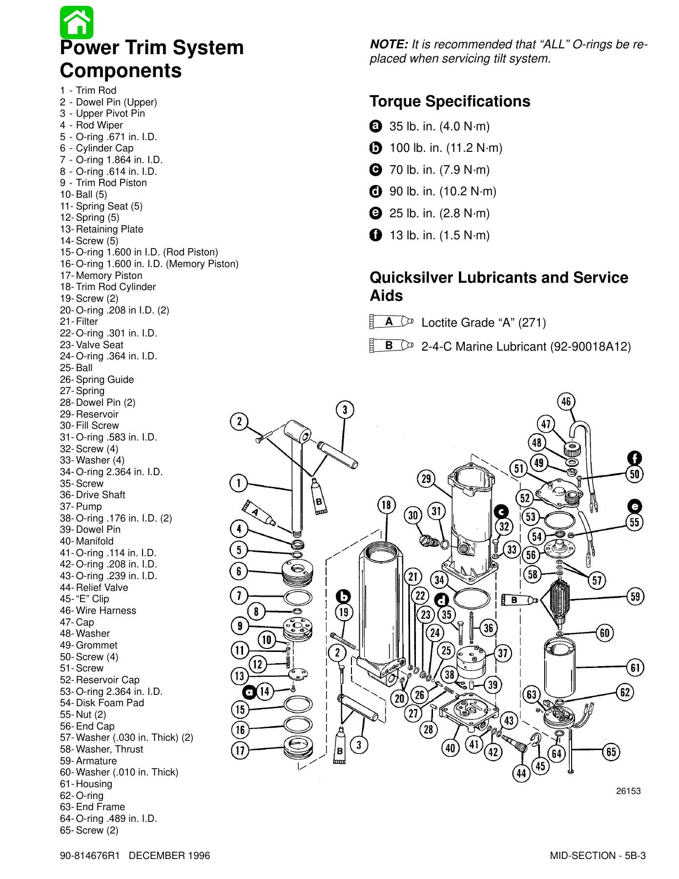
    • 5B β€” Power Trim (Design I): description, trimming characteristics, tilting manually, trim-in angle adjustment, flow diagrams for trim up, trim down, hydraulic tilt, maximum tilt blow off, shock function up, shock function return, manual tilt, troubleshooting, electrical system, removal, disassembly, cleaning, motor and electrical tests, reassembly, installation
    • 5C β€” Power Trim (Design II): same coverage as Design I with Design II specific component breakdowns and flow diagrams
    • 5D β€” Power Trim (Design III): same coverage with Design III specific components and procedures
    • 5E β€” Power Trim (Design IV): full theory of operation, trim up, tilt up, maximum tilt, down mode, shock function up and return, manual tilt, troubleshooting, removal, disassembly, cleaning, reassembly, installation
    • 5F β€” Manual Tilt System (Design I, II, III): flow diagrams, hydraulic troubleshooting, removal, disassembly, cleaning, valve block reassembly, shock rod reassembly, bleeding, installation
    • 5G β€” Manual Tilt System (Design IV): flow diagrams, tilt up, tilt down, slow tilt down under high thrust, underwater strike, shock function, troubleshooting, removal, disassembly, reassembly, bleeding, installation
  • Section 6 β€” Lower Unit:
    • 6A β€” Lower Unit: draining and inspecting gear lubricant, trim tab and propeller removal, gear housing removal, disassembly, water pump removal, bearing carrier and propeller shaft removal, drive shaft and pinion gear removal, lubrication sleeve removal, forward gear and bearing removal, shift shaft removal, drive shaft needle bearing removal, cleaning and inspection, gear housing reassembly, drive shaft needle bearing installation, shift shaft bushing installation, forward gear and bearing reassembly, bearing carrier reassembly, pinion gear depth check, propeller shaft reassembly, forward gear backlash check, water pump reassembly, gear housing installation, filling with lubricant, propeller and trim tab installation
    • 6B β€” Jet Drive: jet pump assembly, boat selection for jet power, engine horsepower selection, transom height, outboard mounting height, water testing, cavitation checks, shift cable installation, drive shaft bearing lubrication, impeller removal and installation, steering pull adjustment, impeller clearance adjustment, worn impeller service, liner replacement, jet drive removal and installation, water pump removal and installation, bearing carrier removal and installation, bearing carrier disassembly and reassembly, seal installation, drive shaft ball bearing installation, jet drive tiller handle adaptor kit installation
  • Section 7 β€” Outboard Motor Installation/Attachments:
    • 7A β€” Installation/Attachments: installing outboard on transom, recommended mounting height, centerline location, drilling mounting holes, lifting outboard, securing to transom, Ride-Guide steering kit installation for single and dual outboards, steering coupler assembly, trim tab adjustment, selecting steering and remote control cables, remote control installation, shift cable installation and adjustment, throttle cable installation and adjustment, connecting remote control wiring to engine, power trim wiring connections, battery connections, stop switch wiring
    • 7B β€” Tiller Handle and Co-Pilot: tiller handle components, throttle cable replacement, tiller handle installation, shift link rod installation, throttle cable installation, lanyard stop switch wiring, neutral start switch wiring, battery connections, Co-Pilot installation, shift interlock adjustment
    • 7C β€” Rewind Starter: components, disassembly, cleaning and inspection, reassembly, installing used and new rewind springs, rope installation, rewind spring tension adjustment
  • Section 8 β€” Oil Injection System: Operation of the oil injection system, components, flow system, pump drive assembly, pump drive system, oil pump to powerhead assembly, set up instructions, filling with oil, bleeding air from inlet and outlet hoses, operation checks, required remote control or ignition switch assembly, troubleshooting chart, installing drive gear onto crankshaft, oil pump volume (flow) test, oil warning module removal and installation, engine mounted oil reservoir removal and installation

What This Mercury Service Manual Gives You

This 1996 Mercury 30 Jet and 40 HP 4-cylinder outboard service manual is the same document Mercury Marine published for its dealers and factory service personnel. Every procedure is written for technicians who service these specific engines, and every specification β€” torque values, DVA voltage readings, float levels, jet sizes, backlash tolerances, bleed procedures β€” is stated for the exact models and serial number ranges listed on the cover. The manual opens with general information and specifications, then moves through the ignition and charging systems with DVA test tables and troubleshooting flow charts, into the fuel system with WMA7B and WMA9 carburetor service, through the powerhead with complete disassembly and reassembly instructions, then covers every mid-section configuration including four power trim designs and four manual tilt designs, and finishes with the lower unit, jet drive, outboard installation, and oil injection system.

The wiring diagram section alone covers multiple remote control configurations, making electrical diagnosis on these outboards far more practical than guessing at wire colors from a generic diagram. The power trim and manual tilt flow diagrams show exactly how hydraulic fluid moves through each circuit under trim up, trim down, tilt, shock, and manual release modes β€” essential for diagnosing the leaking check balls and O-rings that are common failure points on these systems. The lower unit section covers both the standard gear housing and the jet drive, including impeller clearance adjustment, liner replacement, and bearing carrier service.

Complete PDF Bookmark Tree

Complete Bookmarks

The complete bookmarks in the β€œ1996 Mercury 30 Jet & 40 HP 4-Cylinder Outboard OEM Service Manual” are as follows:

coverp. 1
MODELS 30 JET 40 (4 CYL)p. 1
Noticep. 2
Notice to Users of This Manualp. 2
Cleanliness and Care of Outboard Motorp. 3
Service Manual Outlinep. 4
1p. 5
GENERAL INFORMATION and SPECIFICATIONSp. 5
Table of Contentsp. 6
Propeller Informationp. 7
How to Use this Manualp. 7
General Specificationsp. 8
Propeller Selectionp. 9
Propeller Installationp. 9
Trim β€œIn” Angle Adjustmentp. 10
Power Trim System (Models with Power Trim)p. 10
General Informationp. 10
Checking Trim System Fluid Levelp. 11
Trimming (Models with Power Trim)p. 11
Trimming Outboard β€œOut” (β€œUp”) Characteristicsp. 11
Trimming Outboard β€œIn” (β€œDown”) Characteristicsp. 11
Trim Tab Adjustmentp. 12
Boat Performancep. 12
Test Instructionsp. 12
Boat Test Chart (Example)p. 13
Lubrication Pointsp. 14
Ride-Guide Steering Cable and Pivot Points Lubricationp. 15
Gear Housing Lubricationp. 16
Salt Water Corrosion – Gear Housing Bearing Carrier and Cover Nutp. 16
Periodic Inspectionp. 17
Flushing Outboard Cooling Systemp. 17
Following Complete Submersionp. 18
Salt Water Submersion (Special Instructions)p. 18
Submerged While Running (Special Instructions)p. 18
Submerged Engine (Fresh Water) (Plus Special Instructions)p. 18
Out-of-Season Outboard Storagep. 19
Out-of-Season Battery Storagep. 19
How Weather Affects Engine Performancep. 20
Conditions Affecting Operationp. 21
Detonation: Causes and Preventionp. 21
Compression Checkp. 22
Painting Proceduresp. 23
Decal Applicationp. 24
2ap. 25
IGNITION SYSTEMp. 25
Table of Contentsp. 26
Ignition Systemp. 27
Descriptionp. 27
Red Stator Modelsp. 27
Ignition Troubleshootingp. 28
Checking for Loss of Sparkp. 28
Troubleshooting Test Equipmentp. 28
Ignition Troubleshooting (Engines With Black Stator)p. 29
Ignition Troubleshooting (Engines With Red Stator)p. 32
Ignition Component Testingp. 36
Trigger Testp. 36
Ignition Coil Testp. 36
Stator Test (Red Stator)p. 37
Stator Test (Black Stator)p. 37
Test For Spark (Cranking)p. 38
Primary Voltage Test (Engine Running)p. 38
Ignition (Key) Switch Testp. 39
Mercury (Tilt) Stop Switch Testp. 39
Flywheel Removal and Installationp. 40
Flywheel Removalp. 40
Flywheel Installationp. 41
Ignition Componentsp. 41
Stator Assembly Removalp. 41
Black Stator Installationp. 43
Red Stator Installationp. 44
Trigger Plate Assembly Removalp. 47
Trigger Plate Assembly Installationp. 48
Ignition Coil Removalp. 49
Ignition Coil Installationp. 49
Switch Box Removalp. 49
Switch Box Installationp. 50
2bp. 51
BATTERY, CHARGING SYSTEM and STARTING SYSTEMp. 51
Table of Contentsp. 52
Batteryp. 53
Precautionsp. 53
Operating Outboard without Batteryp. 53
Specific Gravity Readingsp. 53
Electrolyte Levelp. 54
Charging a Discharged Batteryp. 54
Winter Storage of Batteriesp. 55
Battery Charging Systemp. 55
Descriptionp. 55
Battery Charging System Troubleshootingp. 56
Stator Test (Alternator Coils Only)p. 56
Voltage Regulator Testp. 57
Alternator System Testp. 57
Rectifier Testp. 59
Starter Systemp. 60
Starter System Componentsp. 60
Descriptionp. 60
Troubleshooting the Starter Circuitp. 60
Starter Circuit Troubleshooting Flow Chartp. 61
Starter Removal and Installationp. 62
Removalp. 62
Installationp. 62
Bosch Starterp. 63
Starter Cleaning, Inspection and Testingp. 64
Cleaning and Inspectionp. 64
Testingp. 64
Checking Positive Brushes and Terminalp. 65
Testing Negative Brushes for Ground (Bosch)p. 65
Reassemblyp. 66
Starter Solenoid Testp. 68
2cp. 69
TIMING/SYNCHRONIZING/ADJUSTINGp. 69
Table of Contentsp. 70
Timing/Synchronizing & Adjustingp. 71
Specificationsp. 71
Special Toolsp. 71
Timing Adjustmentsp. 71
Carburetor Adjustmentsp. 75
2dp. 76
WIRINGp. 76
Table of Contentsp. 77
Wiring Diagram – Model 30 Jet with 16 Amp Black Statorp. 78
Wiring Diagram – Model 30 Jet with 16 Amp Red Statorp. 79
Wiring Diagram – Model 30 Jet Tiller Handle with 16 Amp Black Statorp. 80
Wiring Diagram — Model 30 Jet Tiller Handle with 16 Amp Red Statorp. 81
Wiring Diagram – Model 40 Electric Start with 9 Amp Black Statorp. 82
Wiring Diagram – Model 40 Electric Start with 16 Amp Black Statorp. 83
Wiring Diagram – Model 40 Electric Start with 16 Amp Red Statorp. 84
Wiring Diagram — Model 40 Electric Start Tiller Handle with 16 Amp Black Statorp. 85
Wiring Diagram — Model 40 Electric Start Tiller Handle with 16 Amp Red Statorp. 86
Wiring Diagram – Model 40 Manual Start with Black Statorp. 87
Wiring Diagram – Model 40 Manual Start with Red Statorp. 88
Power Trim Wiring Diagramp. 89
Commander 2000 Side Mount Remote Control (Power Trim/Tilt Electric Start with Warning Horn) Wiring Diagramp. 90
Commander 2000 Side Mount Remote Control (Electric Start with Warning Horn) Wiring Diagramp. 91
Commander 2000 Side Mount Remote Control (Manual) Wiring Diagramp. 92
Key/Choke Switch Continuity Test (Commander 2000 Side Mount Remote Control)p. 93
Panel Mount Remote Control Wiring Diagramp. 94
Remote Key Switch and Warning Hornp. 95
3p. 96
FUEL SYSTEM AND CARBURETIONp. 96
Table of Contentsp. 97
Specificationsp. 98
Special Toolsp. 98
Fuel System (Carburetor)p. 99
Fuel System (Fuel Pump)p. 100
Fuel Pumpp. 101
General Informationp. 101
Testingp. 101
Troubleshooting Fuel Pumpp. 101
Fuel Pump Removal (Electric Start Model)p. 102
Fuel Pump Disassemblyp. 103
Fuel Pump Exploded View (Design 1)p. 104
Cleaning and Inspectionp. 105
Fuel Pump Installation (Design 1)p. 106
Fuel Pump Exploded View (Design 2)p. 107
Cleaning and Inspectionp. 108
Fuel Pump Installation (Design 2)p. 108
Carburetion Systemp. 109
Fuel System – Troubleshootingp. 109
Troubleshooting Chartsp. 109
Checking for Restricted Fuel Flow Caused by Anti-Siphon Valvesp. 110
Carburetor Adjustmentsp. 110
Initial Starting Adjustmentp. 110
Idle Speed Adjustmentp. 110
Idle Mixture Screw Adjustmentp. 111
Float Adjustmentp. 111
Main (High Speed) Jet Adjustmentp. 112
Vent Jetp. 113
High Altitude Jettingp. 113
Carburetor Jet Orifice Sizes WMA7Bp. 113
Carburetor Jet Orifice Sizes WMA9p. 113
Enrichment Systemp. 114
Enrichener Hose Routed to Carburetor Flangesp. 114
Enrichener Hose Routed to Balance Tubep. 114
Primer Systemp. 115
Enrichner Valve (Manual Operation)p. 115
Enrichment Valve Testp. 116
Enrichener Valve Replacementp. 116
Fuel Line and Primer Bulb Assemblyp. 117
Maintenancep. 117
Fuel Line Clamp Removal and Installationp. 117
Carburetor Removal (Manual Start Model)p. 118
Carburetor Disassembly (Top Carburetor)p. 118
Cleaning and Inspectionp. 122
Carburetor Reassemblyp. 123
Carburetor Installationp. 127
4p. 128
POWERHEADp. 128
Table of Contentsp. 129
Specificationsp. 130
Special Toolsp. 130
General Informationp. 130
Throttle Control Linkagep. 131
Cylinder Block and Crankcase Assemblyp. 133
End Caps and Exhaust Coverp. 135
Crankshaft, Pistons, and Connecting Rodsp. 137
Powerhead Torque Sequence and Torque Specificationsp. 139
Powerhead Removal from Driveshaft Housingp. 140
Electric Start Modelp. 140
Manual Start Modelp. 143
Powerhead Disassemblyp. 145
End Cap Disassemblyp. 150
Crankshaft Disassemblyp. 151
Cleaning and Inspectionp. 154
Cylinder Block and Crankcase Coverp. 154
Cylinder Bore (Cleaning and Inspection)p. 154
Cylinder Bore Sizep. 155
Pistonsp. 155
Measuring Piston Roundnessp. 156
Reed Blocksp. 156
Connecting Rodsp. 157
Cleaning Connecting Rodsp. 159
Crankshaftp. 159
Ball Bearingp. 160
Powerhead Reassemblyp. 160
Crankshaft Reassemblyp. 161
Piston Installationp. 164
Crankshaft Seal Installationp. 166
End Cap Reassemblyp. 167
Cylinder Block Reassemblyp. 168
Installing Powerhead on Driveshaft Housingp. 177
5ap. 179
CLAMP/SWIVEL BRACKET AND DRIVE SHAFT HOUSINGp. 179
Table of Contentsp. 180
Swivel Bracket Componentsp. 181
Transom Bracket Componentsp. 182
Drive Shaft Housing Componentsp. 183
Disassemblyp. 184
Reassemblyp. 184
Tilt Lock Lever/Transom Bracketp. 184
Drive Shaft Housingp. 186
5bp. 188
POWER TRIM (DESIGN 1)p. 188
Table of Contentsp. 189
Power Trim General Informationp. 190
Descriptionp. 190
Trimming Characteristicsp. 190
Trailering Outboardp. 191
Tilting Outboard Up and Down Manuallyp. 191
Trim "In" Angle Adjustmentp. 191
Power Trim System Componentsp. 192
Power Trim Flow Diagrams Design 1p. 193
Troubleshootingp. 200
Determine if Problem is Electrical or Hydraulicp. 200
Trouble Chartp. 200
Hydraulic System Troubleshootingp. 201
Preliminary Checksp. 201
Leak Down Check – Pump and Manifold Assemblyp. 201
Leak Down Check – Pilot Valve Assemblyp. 202
Leak Down Check – Manual Release Valvep. 202
Leakage Past Ball and Seat – Piston Assemblyp. 202
Troubleshooting Flow Diagramp. 203
Electrical System Troubleshootingp. 205
COMMANDER 2000 Side Mount Remote Control (Power Trim/Tilt Electric Start with Warning Horn) Wiring Diagramp. 205
Power Trim System Wiring Diagramp. 206
Troubleshooting the β€œDown” Circuit (When β€œUp” Circuit is OK)p. 207
Troubleshooting the β€œUp” Circuit (When β€œDown” Circuit Is OK)p. 208
Troubleshooting the β€œDown” and β€œUp” Circuits (All Circuits Inoperative)*p. 209
Power Trim System Removalp. 210
Power Trim System Disassemblyp. 211
Trim Rod Removalp. 211
Trim Rod Disassemblyp. 212
Trim β€œMotor” Removalp. 214
Trim β€œMotor” Disassemblyp. 214
Reservoir Assembly Removalp. 215
Oil Pump Removalp. 216
Manifold Removalp. 216
Cleaning and Inspection of Trim Rod Componentsp. 217
Motor and Electrical Tests/Repairp. 218
Trim Pump Motor Testp. 218
Thermal Overload Switch Testp. 218
Armature Testsp. 219
Power Trim System Reassemblyp. 219
Manifold Installationp. 219
Oil Pump Installationp. 220
Trim Motor Reassemblyp. 221
Reservoir Installationp. 222
Trim Rod Reassemblyp. 224
Trim Rod Installationp. 225
Bleeding Power Trim Unitp. 226
Power Trim Unit Installationp. 226
5cp. 228
POWER TRIM (DESIGN II)p. 228
Table of Contentsp. 229
Power Trim General Informationp. 230
Descriptionp. 230
Trimming Characteristicsp. 230
Trailering Outboardp. 231
Tilting Outboard Up and Down Manuallyp. 231
Trim "In" Angle Adjustmentp. 231
Power Trim System Componentsp. 232
Power Trim Flow Diagrams Design IIp. 233
Troubleshootingp. 240
Determining if Problem is Electrical or Hydraulicp. 240
Trouble Chartp. 240
Hydraulic System Troubleshootingp. 241
Preliminary Checksp. 241
Leak Down Check – Pump and Manifold Assemblyp. 241
Leak Down Check – Pilot Valve Assemblyp. 242
Leak Down Check – Manual Release Valvep. 242
Leakage Past Ball and Seat – Piston Assemblyp. 242
Troubleshooting Flow Diagramp. 243
Electrical System Troubleshootingp. 245
COMMANDER 2000 Side Mount Remote Control (Power Trim/Tilt Electric Start with Warning Horn) Wiring Diagramp. 245
Power Trim System Wiring Diagramp. 246
Troubleshooting the β€œDown” Circuit (When β€œUp” Circuit is OK)p. 247
Troubleshooting the β€œUp” Circuit (When β€œDown” Circuit Is OK)p. 248
Troubleshooting the β€œDown” and β€œUp” Circuits (All Circuits Inoperative)p. 249
Power Trim System Removalp. 250
Power Trim System Disassemblyp. 251
Trim Rod Removalp. 251
Trim Rod Disassemblyp. 252
Trim β€œMotor” Removalp. 254
Trim Motor Disassemblyp. 254
Reservoir Assembly Removalp. 255
Oil Pump/Manifold Removalp. 256
Cleaning and Inspection of Trim Rod Componentsp. 257
Motor and Electrical Tests/ Repairp. 258
Trim Pump Motor Testp. 258
Thermal Overload Switch Testp. 258
Armature Testsp. 259
Power Trim System Reassemblyp. 259
Manifold/Oil Pump Installationp. 259
Trim Motor Reassemblyp. 260
Reservoir Installationp. 262
Trim Rod Reassemblyp. 263
Trim Rod Installationp. 264
Bleeding Power Trim Unitp. 265
Power Trim Unit Installationp. 266
5dp. 268
POWER TRIM (DESIGN 3)p. 268
Table of Contentsp. 269
Special Toolsp. 270
Quicksilver Lubricants and Service Aidsp. 270
Power Trim – General Informationp. 270
Descriptionp. 270
Trimming Characteristicsp. 270
Trailering Outboardp. 271
Tilting Outboard Up and Down Manuallyp. 271
Trim β€œIn” Angle Adjustmentp. 271
Power Trim System Componentsp. 272
Troubleshootingp. 273
Determining if Problem is Electrical or Hydraulicp. 273
Hydraulic System Troubleshootingp. 274
Preliminary Checksp. 274
Leak Down Check – Pump and Manifold Assemblyp. 274
Leak Down Check – Pilot Valve Assemblyp. 275
Leak Down Check – Manual Release Valvep. 275
Leaks Past Ball and Seat – Piston Assemblyp. 275
Troubleshooting Flow Diagramp. 276
Electrical System Troubleshootingp. 278
COMMANDER 2000 Side Mount Remote Control (Power Trim/Tilt Electric Start with Warning Horn) Wiring Diagramp. 278
Power Trim System Wiring Diagramp. 279
Troubleshooting the β€œDown” Circuit (When β€œUp” Circuit is OK)p. 280
Troubleshooting the β€œUp” Circuit (When β€œDown” Circuit Is OK)p. 281
Troubleshooting the β€œDown” and β€œUp” Circuits (All Circuits Inoperative)p. 282
Power Trim System Removalp. 283
Power Trim System Disassemblyp. 284
Trim Rod Removalp. 284
Trim Rod Disassemblyp. 285
Trim β€œMotor” Removalp. 287
Trim "Motor" Disassemblyp. 287
Reservoir Assembly Removalp. 287
Manifold Removalp. 288
Cleaning and Inspection of Trim Rod Componentsp. 289
Motor and Electrical Tests/Repairp. 289
Trim Pump Motor Testp. 289
Armature Testsp. 289
Power Trim System Reassemblyp. 290
Manifold Installationp. 290
Trim Motor Reassemblyp. 291
Reservoir Installationp. 292
Trim Rod Reassemblyp. 293
Trim Rod Installationp. 294
Purging Power Trim Unitp. 295
Power Trim Unit Installationp. 295
5ep. 298
POWER TRIM (DESIGN 4)p. 298
Table of Contentsp. 299
Special Toolsp. 300
Theory Of Operationp. 303
Adjustmentsp. 303
Trimming Characteristicsp. 303
Trailering Outboardp. 304
Tilting Outboard Up and Down Manuallyp. 304
Trim Upp. 306
Tilt Upp. 308
Maximum Tiltp. 310
Down Modep. 312
Shock Function Upp. 314
Shock Function Returnp. 316
Manual Tiltp. 318
Troubleshootingp. 319
Preliminary Checksp. 319
Hydraulic System Troubleshooting Flow Chartp. 320
Troubleshooting the Power Trim Electrical Systemp. 324
Power Trim System Removalp. 326
Power Trim Disassemblyp. 327
Trim Motor Removalp. 328
Pump and Components Removalp. 328
Manifold Removalp. 329
Shock Rod Removalp. 329
Shock Rod Disassemblyp. 330
Memory Piston Removalp. 332
Cleaning/Inspection/Repairp. 333
Trim Motor Electrical Testsp. 333
Reassemblyp. 334
O-Ring and Seal Placementp. 334
O-ring Sizesp. 335
O-ring Description and Sizesp. 336
Power Trim Reassemblyp. 337
Shock Rod Reassemblyp. 337
Shock Rod Installationp. 338
Trim Limit Assembly Installationp. 339
Manual Release Valve Installationp. 339
Manifold Installationp. 339
Oil Pump Installationp. 340
Pressure Operated Assembly Installationp. 341
Reservoir/Motor Installationp. 341
Bleeding Power Trim Unitp. 342
Installation of Power Trim Systemp. 342
5fp. 345
MANUAL TILT SYSTEM (DESIGN I, II, III)p. 345
Table of Contentsp. 346
Manual Tilt System Components (Design One and Two)p. 347
Manual Tilt System Components (Design Three)p. 348
Manual Tilt Flow Diagrams Design 1p. 349
Manual Tilt Flow Diagrams Design 2p. 354
Manual Tilt Flow Diagrams Design 3p. 359
Hydraulic System Troubleshootingp. 364
Troubleshooting Flow Chartp. 365
Manual Tilt System Removalp. 367
Manual Tilt System Disassemblyp. 368
Accumulator Removalp. 368
Shock Rod Removalp. 369
Shock Rod Disassemblyp. 370
Valve Block Removalp. 372
Valve Block Disassemblyp. 373
Manual Tilt System Cleaning and Inspectionp. 374
Manual Tilt System Reassemblyp. 374
Valve Block Reassemblyp. 374
Valve Block Installationp. 376
Shock Rod Reassemblyp. 376
Shock Rod Installationp. 378
Instructions for Making Retaining Toolp. 379
Bleeding Manual Tilt Systemp. 380
Manual Tilt System Installationp. 381
5gp. 383
MANUAL TILT SYSTEM (DESIGN 4)p. 383
Table of Contentsp. 384
Special Toolsp. 385
Manual Tilt Componentsp. 386
Manual Trim Flow Diagramsp. 388
Up Circuitp. 388
Down Circuitp. 390
Slow Tilt Down Under High Thrustp. 392
Under Water Strike (Valves Open)p. 394
Shock Function (Valve Closed)p. 396
Shock Function Returnp. 398
Hydraulic System Troubleshootingp. 400
Manual Tilt System Removalp. 401
Manual Tilt System Disassemblyp. 402
Accumulator Removalp. 402
Shock Rod Removalp. 403
Shock Rod Disassemblyp. 404
Valve Block Removalp. 406
Memory PIston Removalp. 406
Valve Block Disassemblyp. 407
Reassembly – O-Ring and Seal Placementp. 408
Actual O-ring Sizesp. 409
O-ring Description and Sizesp. 410
Manual Tilt System Cleaning and Inspectionp. 411
Manual Tilt System Reassemblyp. 411
Valve Block Installationp. 412
Shock Rod Reassemblyp. 413
Shock Rod Installation and Fluid Filling Procedurep. 414
Filling Procedure Option Two Instructions for Making Retaining Toolp. 415
Bleeding Manual Tilt Systemp. 416
Manual Tilt System Installationp. 418
Manual Release Valve Adjustmentp. 419
6ap. 420
GEAR HOUSINGp. 420
Table of Contentsp. 421
Special Toolsp. 422
Quicksilver Lubricants and Service Aidsp. 422
Gear Housing Assembly – Drive Shaft Componentsp. 423
Torque Specificationsp. 423
Lubrication/Sealant Application Pointsp. 423
Gear Housing Assembly – Propeller Shaft Componentsp. 424
Torque Specificationsp. 424
Lubrication/Sealant Application Pointsp. 424
Draining and Inspecting Gear Housing Lubricantp. 425
Trim Tab/Propeller Removalp. 425
Gear Housing Removalp. 426
Gear Housing Disassemblyp. 426
Water Pump Removalp. 427
Bearing Carrier and Propeller Shaft Removalp. 429
Drive Shaft and Pinion Gear Removalp. 431
Lubrication Sleeve Removalp. 432
Forward Gear and Bearing Removalp. 433
Shift Shaft Removalp. 433
Drive Shaft Needle Bearing Removalp. 434
Cleaning and Inspectionp. 434
Gear Housing/Bearing Carrier Castingsp. 434
Bearingsp. 434
Propeller Shaftp. 435
Forward, Reverse an Pinion Gearsp. 435
Sliding Clutchp. 436
Cam Followerp. 436
Water Pump Componentsp. 436
Drive Shaftp. 436
Shift Shaftp. 437
Gear Housing Reassemblyp. 437
Drive Shaft Needle Bearing Installationp. 437
Shift Shaft Bushing Reassembly and Installationp. 437
Lubrication Sleeve Installationp. 438
Forward Gear and Bearing Reassemblyp. 438
Bearing Carrier Reassemblyp. 439
Forward Gear Race Installationp. 440
Drive Shaft Reassembly and Installationp. 440
Checking Pinion Gear Depthp. 441
Propeller Shaft Reassembly and Installationp. 441
Bearing Carrier Installationp. 442
Checking Forward Gear Backlashp. 444
Water Pump Reassembly and Installationp. 444
Gear Housing Installationp. 446
Filling Gear Housing with Lubricantp. 448
Propeller/Trim Tab Installationp. 448
6bp. 450
JET DRIVEp. 450
Table of Contentsp. 451
Jet Pump Assemblyp. 453
Selecting A Boat That Is Best Suited For Jet Powerp. 455
Engine Horsepower Selectionp. 455
Transom Height of the Boatp. 456
Locate Centerline Of The Outboardp. 456
Outboard Mounting Heightp. 456
Water testingp. 457
Shift Cable Installationp. 458
Lubricating The Drive Shaft Bearingp. 459
Impeller Removal and Installationp. 459
Steering Pull Adjustmentp. 461
Impeller Clearance Adjustmentp. 461
Worn (Dull) Impellerp. 461
Liner Replacementp. 462
Jet Drive Removal and Installationp. 462
Water Pump Removal and Installationp. 463
Bearing Carrier Removal and Installationp. 463
Bearing Carrier Disassemblyp. 464
Bearing Carrier Reassemblyp. 464
Installing Lower Sealsp. 464
Installing Upper Sealsp. 465
Installing Drive Shaft Ball Bearingp. 465
Installing Drive Shaftp. 465
Jet Drive Tiller Handle Adaptor Kitp. 467
Installation Instructionsp. 467
Shift Cable Adjustmentp. 470
7ap. 471
OUTBOARD MOTOR INSTALLATION/ATTACHMENTSp. 471
Table of Contentsp. 472
Locate Centerline Of The Boat Transomp. 473
Lifting Outboardp. 473
Installing Outboard On Boat Transom Models Without Transom Clamp Handlesp. 473
Installing Outboard On Boat Transom Models With Transom Clamp Handlesp. 474
Single Cable – Single Outboard Ride Guide Steering Attaching Kit (P/N 19608A3 abd P/N 19609A2) Installationp. 476
Component Removal – Tiller Handle Modelsp. 476
Steering Bracket Installation – Tiller Handle Modelsp. 476
19608A-3 Ride Guide Steering Attaching Kit Installation – Steering Cable Routed for Starboard Entry into Outboard Tilt Tubep. 476
Installing Ride Guide Cable to Outboard Tilt Tubep. 476
Installing Steering Link Rodp. 477
19609A-2 Ride Guide Steering Attaching Kit Installation – Steering Cable Routed for Port Entry into Outboard Tilt Tubep. 478
Installing Ride Guide Cable to Outboard Tilt Tubep. 478
Installing Steering Link Rodp. 479
Maintenance Instructionsp. 479
Single Cable – Dual Outboard Ride Guide Steering Kit (P/N 97933A4) Installationp. 480
Installation Requirementsp. 480
Steering Cable Installation – Cable Routed Down Starboard Side of Boat to Port Outboardp. 481
Installing Steering Link Rodp. 481
Steering Cable Installation – Cable Routed Down Port Side of Boat to Starboard Outboardp. 482
Installing Steering Cablep. 482
Installing Steering Link Rodp. 483
Maintenance Instructionsp. 483
Steering Coupler Assemblyp. 484
Steering Coupler Installationp. 485
Ride-Guide Steering Attachment Extension Couplersp. 486
Trim Tab Adjustmentp. 486
Maintenance Instructionsp. 486
Transom Mounted Ride Guide Attaching Kit Installation (73770A1)p. 487
Clevis Attaching Kit Installation (P/N 70599A4)p. 488
Installation Instructionsp. 488
Maintenance Instructionsp. 489
Steering Cable Installationp. 490
Maintenance Instructionsp. 490
Selecting Steering Cable and Remote Control Cablesp. 491
Remote Control Installationp. 491
Shift Cable Installation and Adjustment to Enginep. 491
Throttle Cable Installation and Adjustment to Enginep. 492
Connecting Remote Control Wiring Harness to Engine Wiring Harness (Electric Start Models)p. 493
Power Trim Wiring Connections (Models So Equipped)p. 494
Battery Connectionsp. 494
Connecting Remote Control Stop Switch Wiring to Engine Wiring (Manual Start Models)p. 495
7bp. 496
TILLER HANDLE AND CO-PILOTp. 496
Table of Contentsp. 497
Tiller Handle Componentsp. 498
Tiller Handle Throttle Cable Replacementp. 499
Tiller Handle Installationp. 502
Shift Link Rod Installationp. 503
Throttle Cable Installationp. 503
Lanyard Stop Switch Wiringp. 505
Neutral Start Switch Wiringp. 506
Battery Connectionsp. 507
Co-Pilot Installation Instructionsp. 508
Shift Interlock Adjustmentp. 509
7cp. 510
REWIND STARTERp. 510
Table of Contentsp. 511
Rewind Starter Componentsp. 512
Torque Specificationsp. 512
Quicksilver Lubricants and Service Aidsp. 512
Rewind Starter Disassemblyp. 513
Cleaning and Inspectionp. 514
Rewind Starter Reassemblyp. 515
Installing Used Rewind Springp. 515
Installing New Rewind Springp. 515
Rope Installationp. 516
Adjusting Rewind Spring Tensionp. 518
8p. 520
Oil Injection System
Table of Contentsp. 521
Operation of the Oil Injection Systemp. 522
Oil Injection Componentsp. 522
Oil Injection Flow Systemp. 523
Pump Drive Assemblyp. 524
Pump Drive Systemp. 524
Oil Pump to Powerhead Assemblyp. 525
Torque Specificationsp. 525
Quicksilver Lubrication/Sealant Application Pointsp. 525
Set Up Instructions for Oil Injection Systemp. 526
Filling the Oil Injection System with Oilp. 526
Bleeding Air from Oil Injectionp. 526
Operation of the Oil Injection Systemp. 527
Check Operation of the Oil Injection System (Engine Running)p. 527
Required Side Mount Remote Control or Ignition Key Switch Assembly to be Used with Engines Equipped with Oil Injectionp. 527
Oil Injection System Troubleshooting Chartp. 528
Installing Drive Gear (for Oil Injection Oil Pump Volume (Flow) Test Pump) Onto Crankshaftp. 529
Oil Warning Modulep. 530
Removalp. 530
Installationp. 531
Engine Mounted Oil Reservoirp. 531
Removalp. 531
Installationp. 532

Who This Manual Is For

This manual suits anyone maintaining, repairing, or rebuilding a Mercury 30 Jet or 40 HP 4-cylinder outboard within the covered serial number ranges. That includes boat owners who do their own maintenance, independent marine mechanics who need factory procedures and specs, and dealers servicing these engines in the field. The level of detail β€” from flywheel removal to connecting rod cleaning to shift shaft bushing installation β€” supports everything from routine 20-hour inspections and impeller changes to complete powerhead overhauls and lower unit rebuilds. Because this is an OEM service manual, the procedures follow the manufacturer’s recommended methods, and the specifications match the engine as it left the factory rather than an aftermarket approximation.

Why Correct Procedures and Specs Matter on This Engine

Two-stroke outboards like these Mercury 30 Jet and 40 HP four-cylinders are sensitive to detonation, cooling, and lubrication. The manual devotes an entire section to detonation causes and prevention, warning that incorrect propeller pitch, over-advanced timing, lean fuel mixture, and inadequate cooling all contribute to piston dome erosion, ring land damage, and roller bearing failure. Following the manual’s timing, synchronization, and carburetor adjustment procedures is the difference between an engine that runs reliably for years and one that fails prematurely. The oil injection system section explains the 50:1 constant ratio pump, the low oil warning circuit, and the bleeding procedure that prevents air from reaching the engine β€” a step that, if skipped, causes catastrophic powerhead damage. The gear housing lubrication and salt water corrosion procedures protect the lower unit from the water intrusion and bearing carrier corrosion that destroy gearcases in saltwater service.

IMAGES PREVIEW

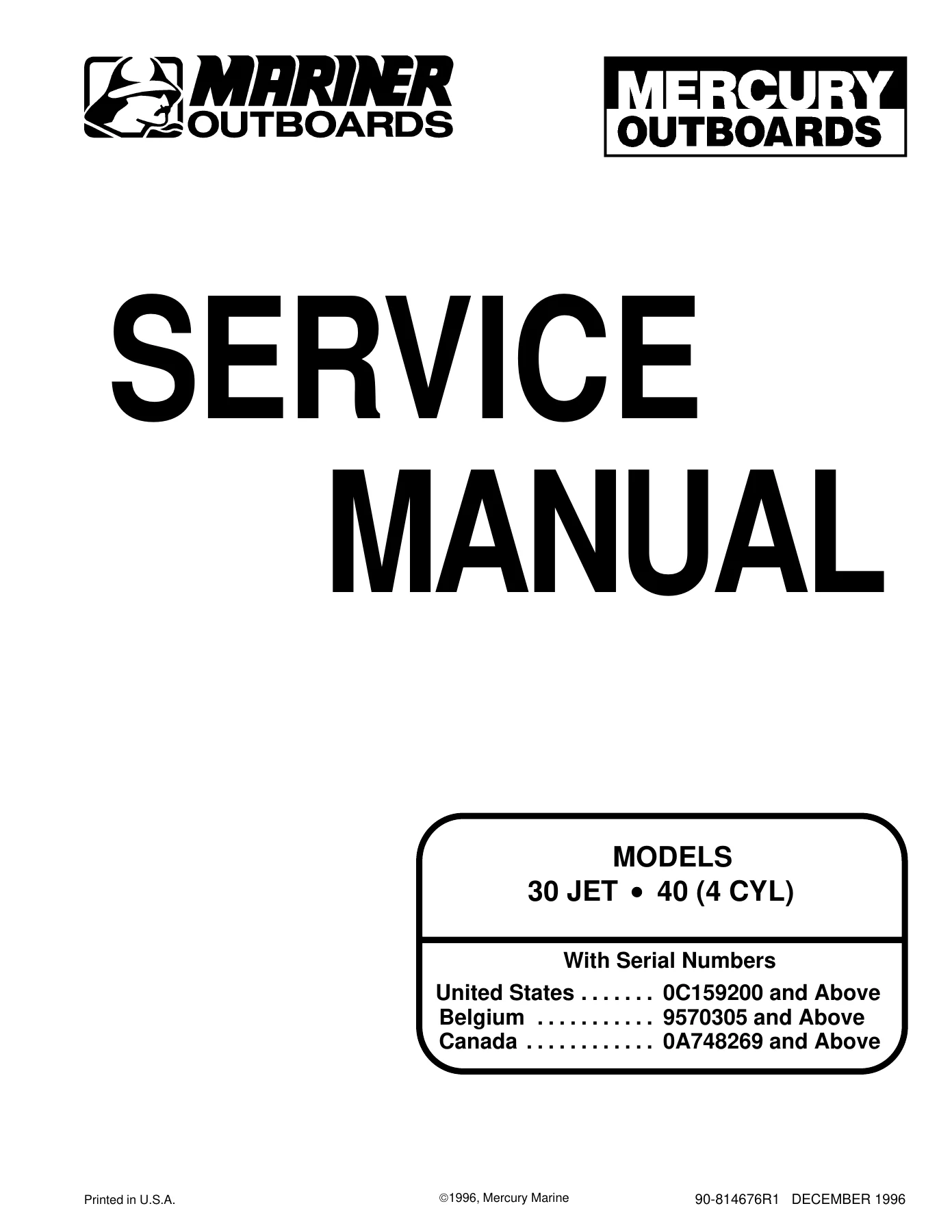
1996 Mercury 30 Jet & 40 HP 4-Cylinder Outboard OEM Service Manual β€” PDF page 1 preview
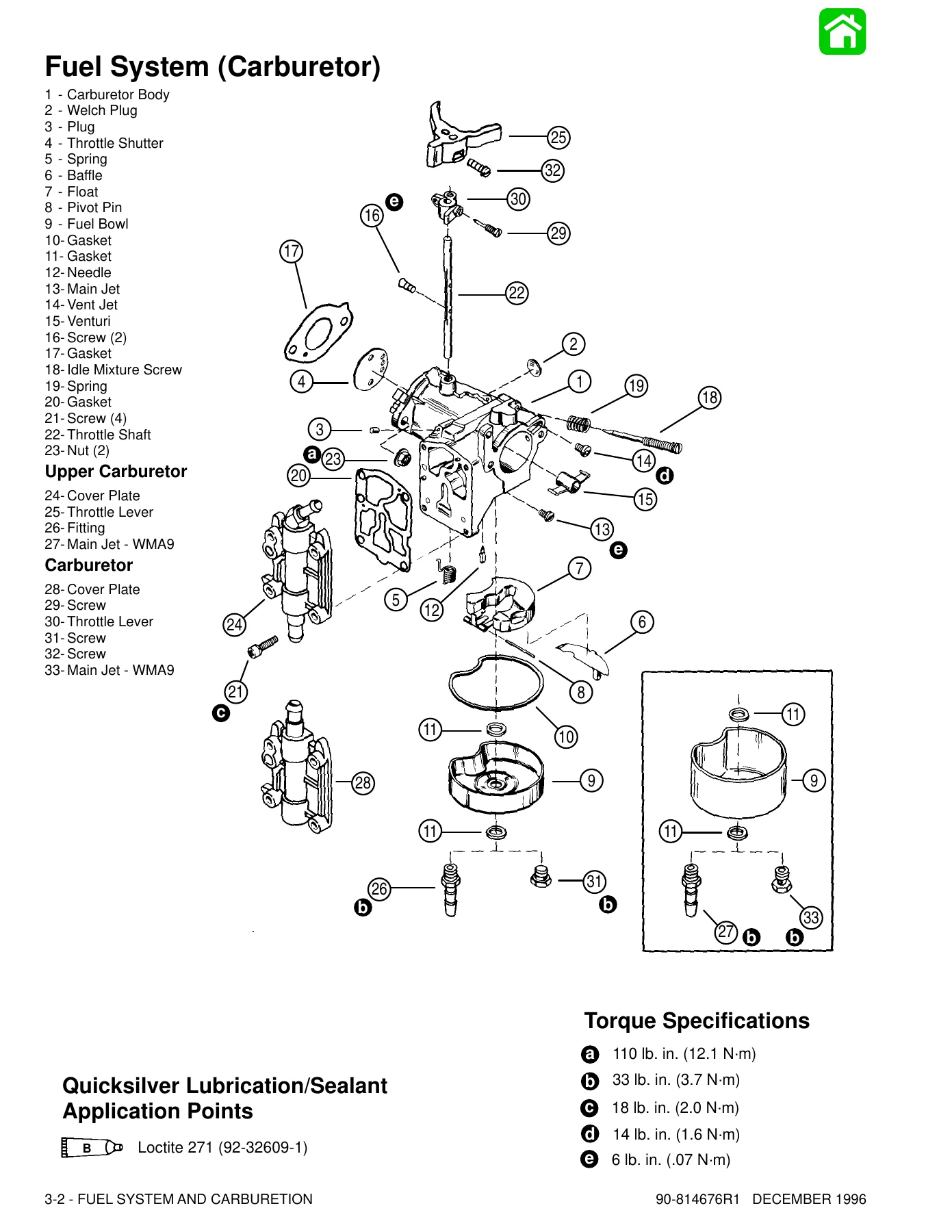
1996 Mercury 30 Jet & 40 HP 4-Cylinder Outboard OEM Service Manual β€” PDF page 99 preview
1996 Mercury 30 Jet & 40 HP 4-Cylinder Outboard OEM Service Manual β€” PDF page 192 preview

Instant PDF Delivery

This Mercury 30 Jet and 40 HP 4-cylinder outboard service manual is delivered as an instant PDF download after payment β€” no shipping, no waiting for a physical book. You can open it on a laptop, tablet, or phone in the workshop, print only the pages you need for the job, and keep the full 532-page manual on hand for every repair, adjustment, and maintenance task your outboard requires. Whether you are tuning carburetors, replacing a stator, rebuilding a power trim unit, servicing a jet drive impeller, or tearing down the powerhead for a full overhaul, the procedures and specifications are right there in the same document Mercury Marine sent to its dealers.

Reviews

There are no reviews yet.

Be the first to review “1996 Mercury 30 Jet & 40 HP 4-Cylinder Outboard OEM Service Manual”

What Our Customers Say

β˜…β˜…β˜…β˜…β˜… Live reviews from customers
Loading customer reviews...
0
    0
    Your Cart
    Your cart is emptyReturn to Shop
    πŸ›’
    Recently Purchased
    πŸ•’ verified order