Description
Yamaha 40V 50H Outboard Service Manual – 63B-28197-5M-11
This is the Yamaha 40V 50H outboard service manual issued under document number 63B-28197-5M-11, published as the 1st Edition in November 2009. It covers the 40V and 50H two-stroke, in-line three-cylinder, 698.0 cmΒ³ outboard motors across the full family of sub-variants, from the manual-starter tiller models through to the electric-start PTT remote control builds. It is written for the working technician and for the informed owner who services their own outboard – covering rigging, diagnosis, disassembly, measurement, assembly and the specified service limits throughout.
File Details
- Manual type: Outboard motor service manual
- Brand / manufacturer: Yamaha (Yamaha Motor Co., Ltd.)
- Models covered: 40V and 50H outboard series
- Document number: 63B-28197-5M-11
- Edition: 1st Edition
- Publication date: November 2009
- Language: English
- File format: PDF
- Approximate page count: ~380 pages
Chapters Covered
- General information – safety while working, how to use this manual, abbreviations, lubricants and sealants, special service tools, tightening torque
- Specification – general features, model designation, serial number, model data, dimensions and weight, performance, power unit, lower unit, bracket unit, fuel and oil requirements, battery, PTT fluid, electrical system technical data, ignition timing, engine speed control, PTT, charging, starting, fuel system, power unit, manual starter, cylinder head, crankcase, oil pump, lower unit, bracket unit, specified tightening torque
- Technical features and description – CDI unit, ignition timing control, ignition cut-off, power unit, oil injection, oil pump operation, cooling system, PTT unit, trim/tilt up and down functions, carburetor idle, medium and high speed operation
- Rigging information – outboard motor installation, dimensions, exterior views per model, clamp bracket, crate pictographs, uncrating, mounting, rigging grommet, tiller handle, wiring harness, shift and throttle cables, friction plate, remote control box, tachometer, battery, propeller selection
- Troubleshooting – troubleshooting procedure, power unit, PTT unit, lower unit fault tables
- Electrical system – wiring harness routing, checking electrical components, peak voltage measurement, ignition unit, pulser coil, charge coil, CDI unit resistance chart, thermoswitch, oil level sensor, alert indicators and buzzer, engine start and shut-off switches, starting unit, starter relay, neutral switch, starter motor, lighting coil, Rectifier Regulator, PTT electrical system, trim sensor
- Fuel system – fuel hose, oil hose, cooling water and breather hoses, fuel filter assembly, fuel pump, intake silencer, carburetor (electric and manual starter), oil tank, oil pump, throttle link and throttle cam
- Power unit – compression check, pulser coil air gap, manual starter, starter motor and CDI unit, wiring harness and ignition coil, power unit assembly, flywheel magnet and base assembly, exhaust cover and reed valve, cylinder head, crankcase, pistons, crankshaft
- Lower unit – propeller, water pump, propeller shaft housing, drive shaft and lower case, shimming workflow, pinion shim (T3), forward gear shim (T1), reverse gear shim (T2) selection tables, gear backlash measurement
- Bracket unit – steering friction, tiller handle, tiller handle electrical component, shift rod and shift bracket, bottom cowling, upper case and mount, exhaust guide, steering arm, clamp bracket, swivel bracket, hydro tilt unit and PTT unit, PTT motor, PTT gear pump, PTT cylinder, bleeding the PTT unit
- Maintenance – maintenance interval chart, predelivery check, break-in, general periodic maintenance, changing gear oil, lubrication points
- Appendix – wiring diagram (40VEO, 50HEDO / 40VMHO, 40VMHD, 50HMHO, 50HMHD / 40VETO, 40VWHTO, 50HETO, 50HWHTO, 50HET) and control unit
Collectively this Yamaha 40V 50H service manual delivers the full lifecycle picture for these two-stroke three-cylinder outboards. It opens with a safety-first general section, moves through detailed specification tables for every major assembly, explains the operating principles behind the CDI ignition, oil injection and PTT systems, then walks through rigging, systematic troubleshooting, and step-by-step disassembly and assembly of the electrical, fuel, power head, lower unit and bracket systems. Measurement limits, torque figures, shimming selection charts and service tool references are woven into the procedures rather than buried in a separate appendix, so the manual reads as a working document rather than a reference catalogue. Wiring diagrams for the three wiring families and the control unit are included at the back for tracing electrical faults.
Complete PDF Bookmark Tree
Complete Bookmarks
The complete bookmarks in the βYamaha 40V 50H Outboard Service Manual 63B-28197-5M-11 – 2009 Edition PDFβ are as follows:
+Contentsp. 3
+General informationp. 5
+Safety while workingp. 6
Rotating partp. 6
Hot partp. 6
Electric shockp. 6
Propellerp. 6
Handling of gasolinep. 6
Ventilationp. 6
Self-protectionp. 7
Working with cranep. 7
Handling of gas torchp. 7
Part, lubricant, and sealantp. 7
Handling of sealantp. 7
Special service toolp. 8
Tightening torquep. 8
Non-reusable partp. 8
Disassembly and assemblyp. 8
+How to use this manualp. 9
Manual formatp. 9
Abbreviationp. 10
+Lubricant, sealant, and thread locking agentp. 11
Special service toolp. 13
+Specificationp. 18
+Model featurep. 20
General featurep. 20
Model designationp. 21
Serial numberp. 21
+Model datap. 22
Dimension and weightp. 22
Performancep. 23
Power unitp. 24
Lower unitp. 26
Bracket unitp. 27
Fuel and oil requirementp. 28
Battery requirementp. 29
PTT fluid requirementp. 29
+Electrical system technical datap. 30
Ignition timing control systemp. 30
Engine speed control systemp. 34
PTT systemp. 34
Charging systemp. 35
Starting systemp. 36
+Fuel system technical datap. 37
+Power unit technical datap. 41
Power unitp. 41
Manual starterp. 42
Cylinder head assemblyp. 43
Crankcase assemblyp. 44
Oil pumpp. 47
+Lower unit technical datap. 47
+Bracket unit technical datap. 49
+Specified tightening torquep. 51
Rigging informationp. 51
Fuel systemp. 51
Power unitp. 51
Lower unitp. 52
Bracket unitp. 52
PTT unitp. 53
General tightening torquep. 53
+Technical features and descriptionp. 55
+Engine control systemp. 56
CDI unitp. 57
Ignition timing controlp. 58
Ignition cut-off controlp. 58
+Power unitp. 60
Oil injection systemp. 60
Oil pumpp. 61
Oil pump operationp. 62
+Cooling systemp. 63
+PTT unitp. 64
Trim up functionp. 65
Tilt up functionp. 66
Tilt and trim down functionp. 67
If the outboard motor hits an object in the waterp. 68
+Carburetorp. 69
Idle and low speed operationp. 69
Medium speed operationp. 70
High speed operationp. 71
+Rigging informationp. 73
Outboard motor installationp. 74
+Dimensionp. 75
Exterior 40VEOp. 75
Exterior 40VETO, 50HEDO, 50HET, 50HETOp. 76
Exterior 40VMHO, 50HMHOp. 77
Exterior 40VMHD, 40VWHTO, 50HMHD, 50HWHTOp. 78
Clamp bracket (PTT and hydro tilt models)p. 79
Clamp bracket (manual tilt model)p. 80
Crate top cover pictograph descriptionp. 81
Uncrating procedurep. 82
Outboard motor mountingp. 82
+Installing the rigging grommetp. 84
Rigging grommet descriptionp. 84
Installing the tiller handlep. 84
Installing the wiring harness, shift cable and throttle cablep. 85
Installing the wiring harness, shift cable and throttle cable (manual starter model)p. 87
Installing the friction platep. 87
Installing the remote control box and tachometer (remote control model)p. 88
Installing the batteryp. 88
+Rigging recommendationsp. 89
+Propeller selectionp. 89
Propeller sizep. 89
Selectionp. 90
+Troubleshootingp. 91
+Troubleshooting the outboard motorp. 92
Troubleshooting procedurep. 92
Troubleshooting the power unitp. 93
Troubleshooting the PTT unitp. 101
Troubleshooting the lower unitp. 102
+Electrical systemp. 104
+Electrical component and wiring harness routingp. 106
Portp. 106
Starboardp. 107
Rearp. 109
Topp. 110
Tiller handlep. 111
+Checking the electrical componentp. 113
Measuring the peak voltagep. 113
Using the digital testerp. 113
+Ignition unit and componentp. 113
Checking the ignition sparkp. 113
Checking the spark plug capp. 114
Checking the ignition coilp. 114
Checking the pulser coilp. 115
Checking the charge coilp. 115
Checking the CDI unitp. 116
CDI unit resistance chart (reference)p. 118
Checking the thermoswitchp. 119
Checking the oil level sensor (1 LED indicator model)p. 119
Checking the oil level sensor (3 LED indicator model)p. 120
Checking the alert indicator (1 LED indicator model)p. 120
Checking the alert indicator (3 LED indicator model)p. 120
Checking the alert buzzerp. 121
Checking the engine start switch (electric starter model)p. 121
Checking the engine shut-off switch (electric starter model)p. 122
Checking the engine shut-off switch (manual starter model)p. 123
+Starting unit and componentp. 123
Checking the fuse (electric starter model)p. 123
Checking the starter relay (electric starter model)p. 123
Checking the neutral switch (tiller handle model with electric starter)p. 124
Checking the neutral switch (remote control model)p. 125
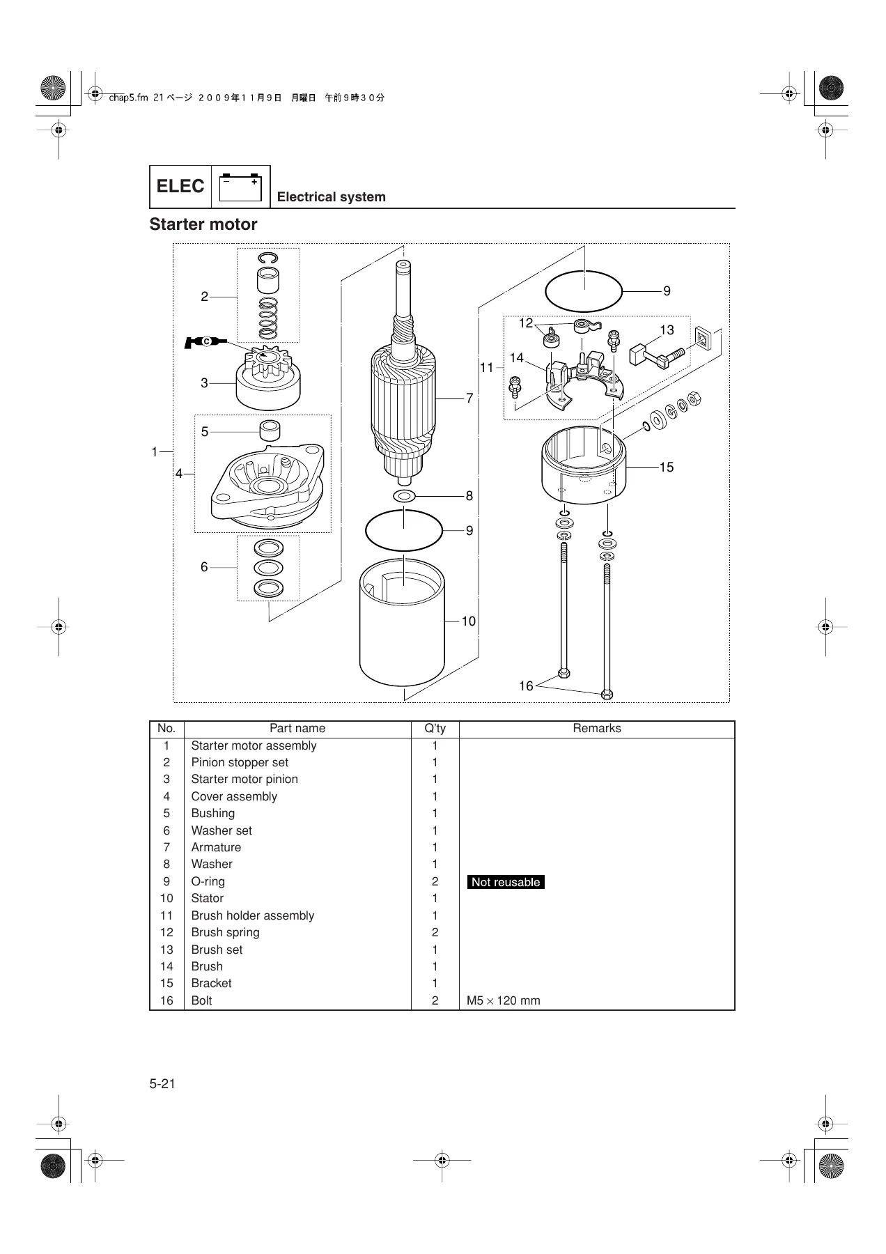
+Starter motorp. 126
Removing the starter motorp. 127
Checking the starter motor operationp. 127
Checking the starter motor pinionp. 127
Disassembling the starter motorp. 127
Checking the armature (starter motor)p. 128
Checking the brushp. 129
Assembling the starter motorp. 129
Installing the starter motorp. 130
+Charging unit and componentp. 130
Checking the lighting coilp. 130
Checking the Rectifier Regulatorp. 131
+PTT electrical systemp. 132
Checking the PTT relayp. 132
Checking the PTT switch (bottom cowling)p. 133
Checking the PTT switch (tiller handle model)p. 134
Checking the trim sensorp. 135
+Fuel systemp. 138
+Hose routingp. 140
Fuel hosep. 140
Oil hose (oil injection model)p. 142
Cooling water hose and breather hosep. 143
+Fuel filter assemblyp. 144
Checking the fuel jointp. 146
Checking the fuel filter assemblyp. 146
Checking the fuel filter elementp. 146
+Fuel pumpp. 147
Checking the fuel pumpp. 148
Disassembling the fuel pumpp. 148
Checking the diaphragm and valvep. 149
Assembling the fuel pumpp. 149
+Intake silencer and carburetorp. 150
Removing the carburetor (electric starter model)p. 152
Removing the carburetor (manual starter model)p. 153
Installing the carburetor (electric starter model)p. 153
Installing the carburetor (manual starter model)p. 154
Synchronizing the carburetorp. 154
Checking the engine idle speedp. 156
+Carburetor (electric starter)p. 157
Disassembling the carburetorp. 160
Checking the carburetorp. 160
Checking the Prime Startp. 160
Assembling the carburetorp. 161
+Carburetor (manual starter)p. 162
Disassembling the carburetorp. 164
Checking the carburetorp. 164
Assembling the carburetorp. 164
+Oil tankp. 165
Removing the oil tankp. 167
Disassembling the oil tankp. 167
Checking the check valvep. 167
Checking the oil filterp. 168
Checking the oil tankp. 168
Assembling the oil tankp. 168
Installing the oil tankp. 168
+Oil pumpp. 170
Removing the oil pumpp. 171
Checking the check valvep. 171
Checking the oil pumpp. 171
Installing the oil pumpp. 171
Adjusting the oil pump link rodp. 172
Bleeding the oil injection systemp. 172
+Throttle link and throttle camp. 173
Removing the control lever and throttle camp. 174
Installing the control lever and throttle camp. 174
Adjusting the throttle link rodp. 175
+Power unitp. 178
+Power unit (check and adjustment)p. 180
Checking the compression pressurep. 180
Checking the pulser coil air gapp. 180
Adjusting the pulser coil air gapp. 181
+Manual starterp. 182
Removing the manual starterp. 184
Disassembling the manual starterp. 184
Checking the manual starterp. 185
Checking the spiral springp. 185
Assembling the manual starterp. 185
Installing the manual starterp. 187
Adjusting the start-in-gear protection cablep. 187
Measuring the starter ropep. 188
Starter motor and CDI unitp. 189
+Wiring harness and ignition coilp. 190
Removing the electrical component (electric starter and PTT models)p. 192
Installing the electrical component (electric starter and PTT models)p. 193
Removing the electrical component (manual starter model)p. 196
Installing the electrical component (manual starter model)p. 196
+Power unit assemblyp. 197
Removing the power unit (electric starter and PTT models)p. 199
Removing the power unit (manual starter model)p. 200
Installing the power unit (electric starter and PTT models)p. 201
Installing the power unit (manual starter model)p. 203
+Flywheel magnet and base assemblyp. 205
Removing the flywheel magnetp. 207
Disassembling the base assemblyp. 207
Assembling the base assemblyp. 208
Installing the flywheel magnetp. 208
+Exhaust cover and reed valvep. 210
Removing the reed valve assemblyp. 212
Checking the reed valve assemblyp. 212
Disassembling the reed valve assemblyp. 212
Checking the reed valvep. 212
Assembling the reed valve assemblyp. 212
Installing the reed valve assemblyp. 213
Removing the thermostatp. 213
Checking the thermostatp. 213
Installing the thermostatp. 214
Removing the exhaust coverp. 214
Checking the exhaust coverp. 215
Installing the exhaust coverp. 215
+Cylinder headp. 216
Removing the cylinder headp. 217
Checking the cylinder headp. 217
Checking the spark plugp. 217
Installing the cylinder headp. 218
+Crankcasep. 219
Removing the crankcase and oil seal housingp. 222
Disassembling the oil seal housingp. 222
Checking the oil seal housingp. 223
Removing the oil pump driven gear (oil injection model)p. 223
Checking the oil pump driven gearp. 223
Removing the crankshaft assemblyp. 223
Disassembling the crankshaft assemblyp. 223
Checking the oil pump drive gearp. 224
Checking the piston pin diameterp. 224
Checking the connecting rod small end inside diameterp. 224
Checking the cylinder blockp. 224
Checking the cylinder block anodep. 224
Checking the piston diameterp. 224
Checking the piston ringp. 225
Checking the piston ring side clearancep. 225
Checking the piston pin boss inside diameterp. 225
Checking the piston ring end gapp. 225
Checking the cylinder borep. 226
Checking the crankshaftp. 226
Checking the connecting rod small end axial playp. 226
Checking the connecting rod big end side clearancep. 226
Assembling the pistonp. 226
Assembling the crankshaftp. 227
Assembling the oil seal housingp. 227
Installing the crankshaft assemblyp. 228
Installing the crankcase assembly and oil seal housingp. 228
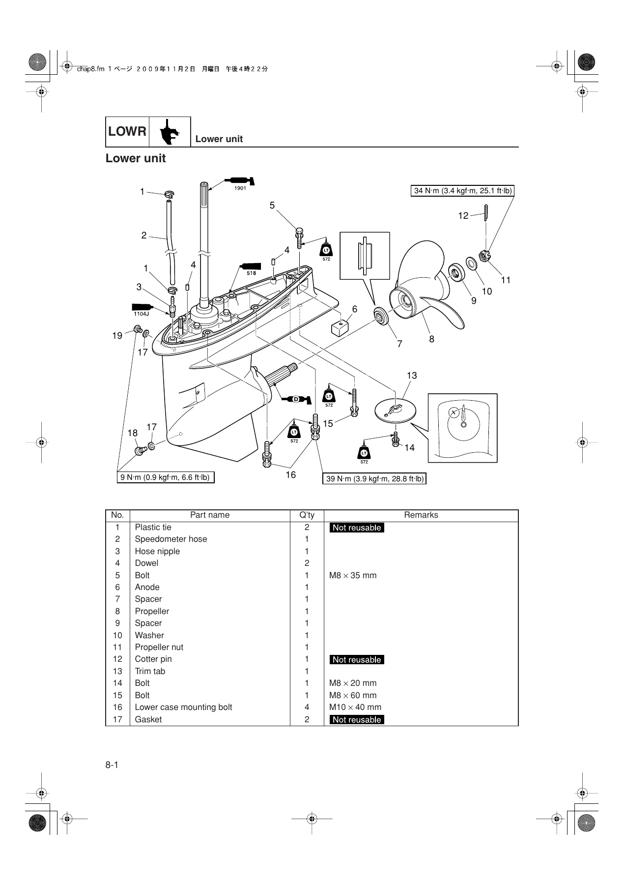
+Lower unitp. 230
+Lower unitp. 232
Removing the lower unitp. 234
Checking the propellerp. 234
Checking the lower unit anodep. 234
+Water pumpp. 235
Removing the water pumpp. 236
Checking the water pumpp. 236
+Propeller shaft housingp. 237
Removing the propeller shaft housing assemblyp. 238
Disassembling the propeller shaft assemblyp. 238
Disassembling the propeller shaft housing assemblyp. 238
Checking the propeller shaftp. 239
Checking the dog clutchp. 239
Checking the propeller shaft housingp. 239
Checking the reverse gearp. 239
Assembling the propeller shaft assemblyp. 239
Assembling the propeller shaft housing assemblyp. 239
+Drive shaft and lower casep. 241
Removing the drive shaft, oil seal housing, and shift rodp. 243
Disassembling the oil seal housingp. 243
Disassembling the drive shaftp. 244
Disassembling the forward gearp. 244
Disassembling the lower casep. 244
Checking the shift rodp. 245
Checking the pinionp. 245
Checking the forward gearp. 245
Checking the drive shaftp. 245
Checking the lower casep. 245
Assembling the lower casep. 245
Assembling the forward gearp. 247
Assembling the drive shaftp. 247
Assembling the oil seal housingp. 248
Installing the shift rod, oil seal housing, and drive shaftp. 248
Installing the propeller shaft housing assemblyp. 249
Installing the water pumpp. 250
Checking the lower unit for air leakagep. 250
Installing the lower unitp. 251
+Shimmingp. 253
Shimming workflowp. 253
Shimming check sheetp. 254
Measuring the forward and reverse gear backlash before disassemblyp. 256
Shimmingp. 259
Shim locationp. 259
Selecting the pinion shim (T3)p. 260
Pinion shim (T3) selection tablep. 263
Measuring the forward gear backlashp. 265
Adjusting the forward gear shim (T1) thicknessp. 265
Forward gear shim (T1) selection chartp. 267
Measuring the reverse gear backlashp. 268
Adjusting the reverse gear shim (T2) thicknessp. 268
Reverse gear shim (T2) selection chartp. 270
+Bracket unitp. 273
+Steering frictionp. 276
Removing the friction platep. 278
Disassembling the friction platep. 278
Assembling the friction platep. 278
Installing the friction platep. 279
+Tiller handlep. 280
Disassembling the tiller handlep. 283
Assembling the tiller handlep. 284
+Tiller handle (electrical component)p. 288
Disassembling the electrical componentp. 289
Assembling the electrical componentp. 289
+Shift rod and shift bracketp. 290
Disassembling the shift rodp. 291
Assembling the shift rodp. 291
Bottom cowlingp. 292
Upper case and mount (L-transom model)p. 295
+Upper case and mount (S-transom model)p. 297
Removing the upper casep. 299
Installing the upper casep. 299
Upper case (L-transom model)p. 301
+Upper case (S-transom model)p. 302
Disassembling the upper casep. 303
Assembling the upper casep. 303
Exhaust guide (L-transom model)p. 304
+Exhaust guide (S-transom model)p. 305
Disassembling the exhaust manifoldp. 306
Checking the exhaust manifoldp. 306
Assembling the exhaust manifoldp. 306
+Steering armp. 308
Removing the steering armp. 309
Installing the steering armp. 309
+Clamp bracket (manual tilt model)p. 311
Removing the clamp bracketp. 314
Installing the clamp bracketp. 314
+Swivel bracket (manual tilt model)p. 317
Disassembling the swivel bracketp. 318
Assembling the swivel bracketp. 318
+Clamp bracket and swivel bracket (hydro tilt and PTT models)p. 320
Removing the clamp bracket (hydro tilt and PTT models)p. 322
Installing the clamp bracketp. 322
Adjusting the trim sensor (PTT model)p. 324
+Hydro tilt unit and PTT unitp. 325
Removing the hydro tilt unitp. 327
Checking the hydro tilt unitp. 327
Checking the hydro tilt anodep. 327
Installing the hydro tilt unitp. 327
Removing the PTT unitp. 328
Checking the PTT anodep. 328
Installing the PTT unitp. 328
+PTT motorp. 330
Removing the PTT motorp. 332
Disassembling the PTT motorp. 332
Checking the armature (PTT motor)p. 332
Checking the brushp. 333
Assembling the PTT motorp. 333
Installing the PTT motorp. 334
+PTT gear pump unitp. 335
Removing the gear pumpp. 337
Checking the filterp. 337
Checking the manual valvep. 337
Installing the gear pumpp. 337
+PTT gear pumpp. 339
Disassembling the gear pumpp. 340
Checking the gear pumpp. 340
Checking the valve sealp. 340
Assembling the gear pumpp. 340
+PTT cylinderp. 342
Disassembling the tilt cylinderp. 344
Disassembling the trim cylinderp. 344
Checking the PTT cylinder and pistonp. 345
Assembling the trim cylinderp. 346
Assembling the tilt cylinderp. 347
Bleeding the PTT unitp. 348
+Maintenancep. 351
+Outlinep. 352
Maintenance interval chartp. 352
+Predelivery checkp. 354
Checking the batteryp. 354
Checking the cooling water pilot holep. 354
Checking the engine oil levelp. 355
Checking the engine start switch and engine shut-off switchp. 355
Checking the fuel systemp. 356
Checking the gear oil levelp. 356
Checking the gear shift and throttle operationp. 356
Checking the outboard motor mounting heightp. 356
Checking the PTT systemp. 357
Checking the steering systemp. 357
Checking the throttle cable and shift cablep. 357
Checking the hydro tilt systemp. 358
Checking the manual tilt systemp. 358
Test runp. 359
Break-inp. 359
After test runp. 359
+General periodic maintenancep. 359
Checking the anodep. 359
Checking the batteryp. 359
Checking the cooling water passagep. 359
Checking the engine idle speedp. 360
Checking the engine oil levelp. 360
Checking the oil filter (oil injection model)p. 360
Checking the oil tank (oil injection model)p. 360
Checking the check valve (oil injection model)p. 360
Adjusting the oil pump link rod (oil injection model)p. 360
Checking the oil level alert system (oil injection model)p. 360
Checking the engine start switch and engine shut-off switchp. 360
Checking the fuel filterp. 360
Checking the fuel joint and fuel hosep. 361
Changing the gear oilp. 361
Checking the gear oil levelp. 362
Lubricating the outboard motorp. 362
Checking the propellerp. 363
Checking the PTT fluid levelp. 363
Checking the PTT operationp. 363
Adjusting the shift cablep. 363
Checking the spark plugp. 363
Checking the thermostatp. 364
Adjusting the throttle link rod and throttle cablep. 364
Checking the top cowlingp. 364
Checking the water pumpp. 364
Indexp. 365
+Appendixp. 371
+Wiring diagramp. 372
How to use the wiring diagramp. 372
40VEO, 50HEDOp. 375
40VMHO, 40VMHD, 50HMHO, 50HMHDp. 377
40VETO, 40VWHTO, 50HETO, 50HWHTO, 50HETp. 379
Control unitp. 380
What This Manual Lets You Do
With the Yamaha 40V 50H service manual open on the bench, the tasks that usually require a dealer become realistic to carry out yourself:
- Diagnose no-start, poor idle, misfire, stalling, overheat, low oil alert and battery-discharge symptoms using the dedicated troubleshooting tables for the power unit, PTT unit and lower unit
- Test the CDI unit, pulser coil, charge coil, ignition coils, Rectifier Regulator, thermoswitches, oil level sensors, starter relay and neutral switch with the specified peak voltage and resistance values
- Overhaul the fuel system – fuel filter assembly, fuel pump diaphragm and valves, carburetors, oil tank, oil pump and check valves – using the pressure and vacuum leak-down checks
- Remove, disassemble, inspect and reinstall the power head: cylinder head, exhaust cover, reed valves, crankcase, crankshaft, pistons, rings and bearings with all warpage, bore, runout and clearance limits
- Rebuild the lower unit, including the water pump, propeller shaft housing, drive shaft, forward and reverse gears, with the pinion (T3), forward gear (T1) and reverse gear (T2) shim selection tables and gear backlash measurement procedure
- Service the PTT system – motor, gear pump, relief valves, trim and tilt cylinders, trim sensor adjustment and bleeding procedure
- Rig the outboard correctly: transom mounting height, clamp bracket torque, shift and throttle cable adjustment, friction plate, propeller selection and battery requirements
- Follow the maintenance interval chart for predelivery checks, break-in and ongoing periodic service
Getting these procedures and specifications right matters on a two-stroke outboard. Incorrect ignition timing, an incorrectly shimmed pinion, an over- or under-torqued cylinder head, or a PTT unit bled incorrectly can all turn a minor service into an expensive failure. This manual puts the manufacturer’s procedures, torque values, measurement limits and service tool references in front of you so the work is done to the correct standard.
Delivery
The manual is delivered as an instant-download PDF immediately after purchase. No shipping, no waiting for a physical book. Read it on a laptop, tablet or phone in the workshop, print the pages you need for the job in front of you, and keep the whole document on hand for every future service.
Reviews
There are no reviews yet.