
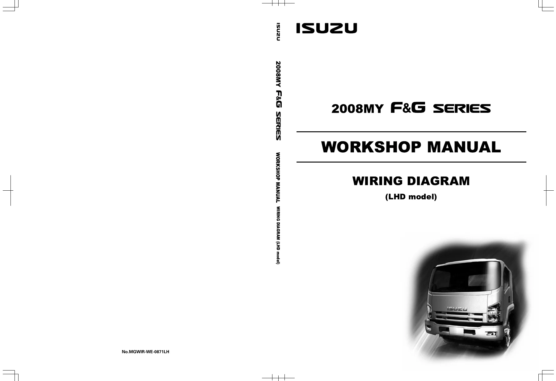
2008 Isuzu F & G Series LHD Wiring Diagram Workshop Manual – MGWIR-WE-0871LH
Original price was: $34.95.$21.95Current price is: $21.95.
Complete left-hand drive wiring diagram workshop manual for the 2008 Isuzu F & G Series trucks. Covers every circuit, relay, fuse, connector and harness on the vehicle, from engine management and ABS to lighting, HVAC and PTO. Instant PDF download.
Description
Isuzu F & G Series LHD Wiring Diagram Workshop Manual
This is the official wiring diagram workshop manual for the 2008 model year Isuzu F & G Series trucks built in left-hand drive configuration. Issued under document number MGWIR-WE-0871LH and covering the entire 9D Wiring System section, it is the single most useful reference for anyone tracing an electrical fault, adding accessories, repairing a harness, or diagnosing a body control, engine management, transmission or braking issue on these trucks. Rather than a generic guide, the 2008 Isuzu F & G Series LHD Wiring Diagram Workshop Manual is laid out exactly the way an Isuzu technician needs it: circuit by circuit, connector by connector, with grounding points, splice locations and harness routing all mapped.
File Details
- Manual type: Wiring Diagram Workshop Manual
- Brand: Isuzu
- Model range: F & G Series (LHD model)
- Model year: 2008MY
- Document number: MGWIR-WE-0871LH
- Edition: Second Edition
- Publication date: October 2008
- Language: English
- Page count: 222
- File format: PDF
- Section: 9D Body, Cab and Accessories – Wiring System
Chapters Covered
- Electric Equipment – Reading the Circuit Diagram
- Parts for Electrical Circuit, Connector and Joint Connection
- Notes for Working on Electrical Items
- Fuse, Fusible Link and Slow-Blow Fuse
- Relay, Diode – Specifications and Configurations
- Main Data and Specifications
- Fuse, Fusible Link and Slow-Blow Fuse Location
- Power Distribution (1/4 to 4/4)
- Relay Location and Relay List
- Diode Location
- Cab Junction Block, Connector Box and Junction Block Connector Locations
- Joint Connection and Weld Splice Location
- Joint Connection Circuit
- Reference Table of Weld Splice
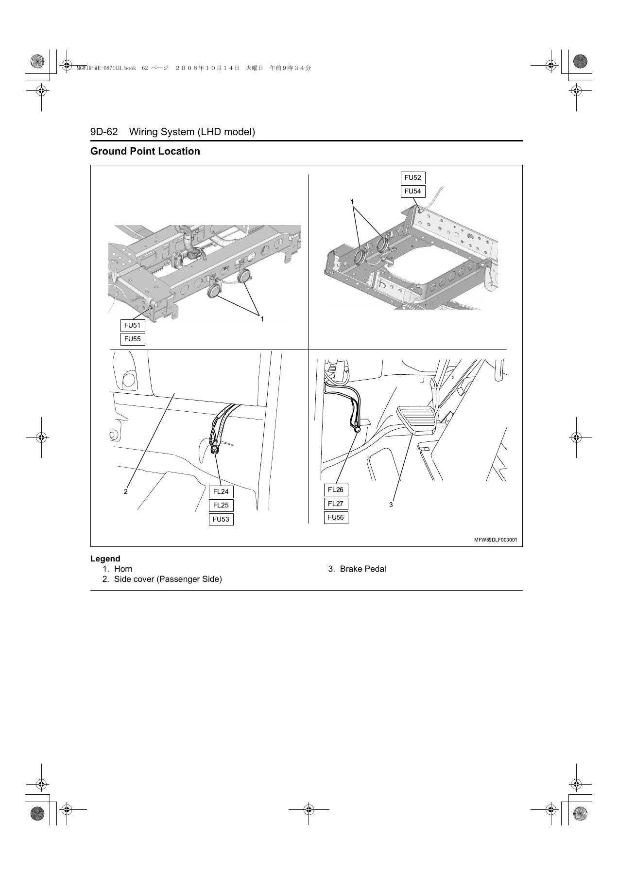
- Grounding Point Circuit and Ground Point Location
- Cable Harness Routing
- Controller Area Network (CAN)
- Starter and Charging Circuit
- Instrument Panel (IP) Cluster and Warning
- Data Link Connector (DLC)
- Engine Control Module (ECM) – 4HK1 and 6HK1
- Transmission Control Module (TCM/Smoother)
- ZF Transmission
- Air Suspension Control Unit
- Electronic Hydraulic Control Unit (EHCU)
- ABS Control Unit / ABS/ASR Control Unit
- HSA (Hill Start Aid) System
- Supplemental Restraint System (SRS) Airbag System
- Headlight (Halogen) and Headlight Manual Leveling
- Fog Light / Clearance Light and Rear Fog Light
- Taillight / Stoplight / Cornering Light
- Horn and Backup Light
- Body Control Module (BCM)
- Windshield Wiper and Washer
- Power Door Lock / Keyless Entry
- Power Window
- Remote Mirror / Mirror Heater
- Dome Light / Fluorescent Light
- Roof-Mounted Clearance Light
- Audio, Cigarette Lighter and Seat Belt
- Heater and Air Conditioning (Manual)
- Exhaust Brake and Cab Power Tilt
- Differential Lock, Front Drive
- Power Take-Off (PTO)
- Immobilizer Control Unit (ICU)
- Tachograph
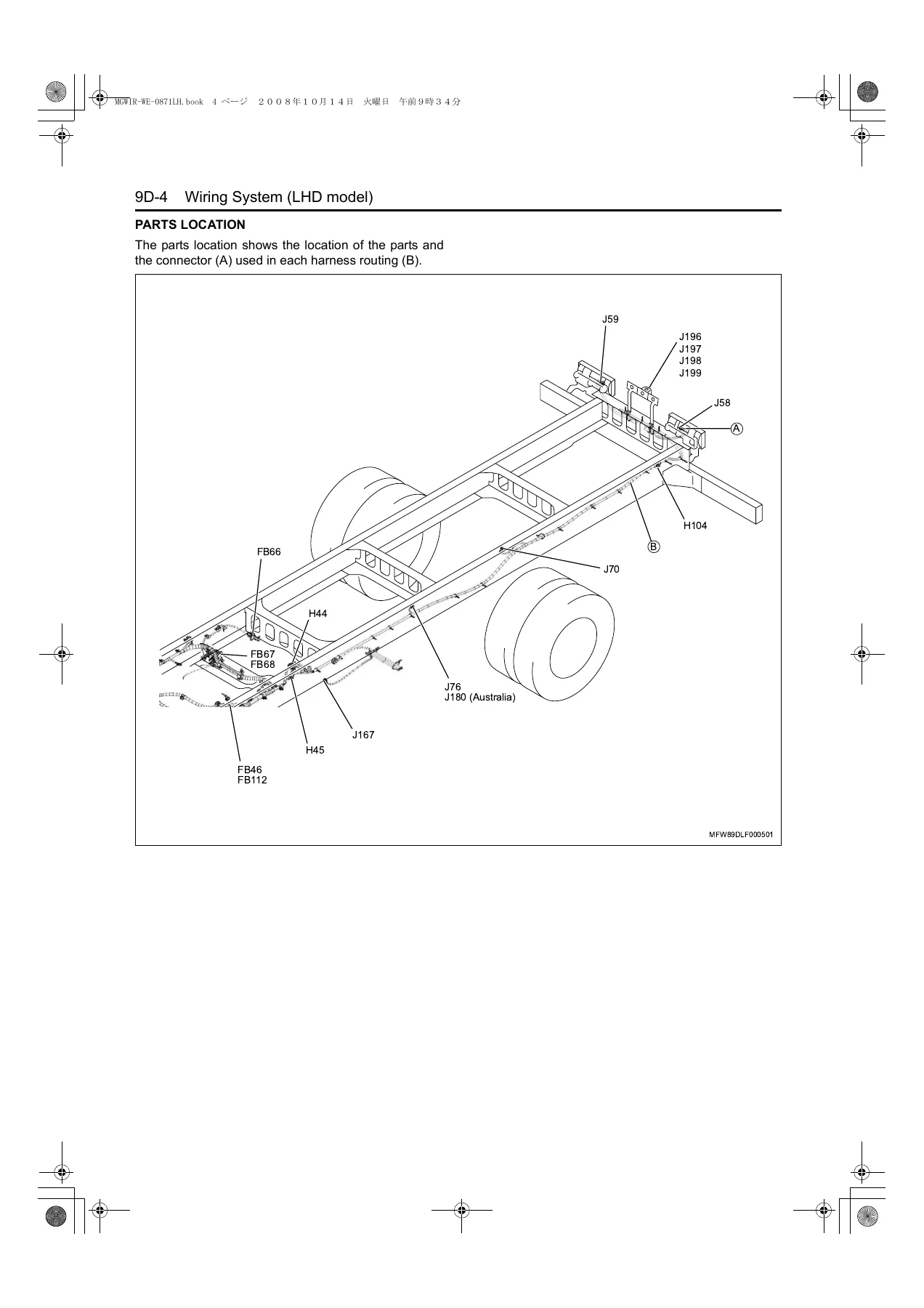
- Parts Locations
- Connector List
What separates this Isuzu wiring diagram manual from a plain schematic set is the amount of supporting structure around each circuit. Alongside the full circuit diagrams, the document gives you relay and diode internal configurations with terminal numbers, slow-blow fuse ratings with their case colours and maximum circuit currents, the specific fuse and fusible link numbers as they appear on the chassis relay box and cab junction block, and a complete weld splice and joint connection reference. Wire colour coding, wire sizing in AWG cross-reference, and the circuit numbering convention used throughout the diagram are all explained up front, so you can read any page in the manual without guesswork. The parts location illustrations then show where each connector and harness physically lives on the cab, frame and engine, which is the step most people get stuck on when a fault code points at a component they cannot find.
What You Can Diagnose and Repair With It
Coverage runs the length of the truck. On the powertrain side, the manual documents the ECM wiring for both the 4HK1 and 6HK1 engines, including sensors, injectors, EGR valve, intake throttle valve, fuel rail pressure sensor and regulator, glow circuit and starter cut relay. Transmission circuits cover the TCM/Smoother unit, its solenoids and speed sensors, plus the ZF transmission variant. Chassis electronics include the ABS/ASR control unit, EHCU, air suspension control unit with its height sensors and magnetic valves, and the HSA hill start aid system. Body and cab coverage is just as deep: body control module, keyless entry and power door lock, power windows, remote and heated mirrors, wiper and washer, roof-mounted clearance lights, dome and fluorescent lighting, audio, cigarette lighter, SRS airbag and the immobilizer control unit. There is also a full section on the tachograph wiring and the cab power tilt circuit.
Because this is the LHD wiring diagram workshop manual as issued for the 2008 F & G Series, the circuit numbering, connector IDs, splice references and junction block layouts match the truck in front of you. That matters when a wiring repair needs to be done to the correct wire size and colour, or when you are chasing an intermittent ground and need the actual grounding point rather than an approximation. Whether you are diagnosing a no-start on a 4HK1, tracking a short in the ABS harness, adding a PTO circuit, or simply replacing a blown slow-blow fuse with the correct rated part, the answer is in this manual.
IMAGES PREVIEW
Instant PDF Delivery
The 2008 Isuzu F & G Series LHD Wiring Diagram Workshop Manual – MGWIR-WE-0871LH is delivered as an instant PDF download the moment your order completes. There is no shipping, no waiting on a disc, and no region restriction. Read it on a laptop, tablet or phone in the workshop, or print the specific circuit pages you need and take them to the vehicle. Every page is laid out for standard letter and A4 printing, so a fold-out circuit diagram stays readable on paper. Keep the file on your device and you have the complete Isuzu F & G Series electrical reference on hand for every job, at any hour, without needing a dealer terminal or an online subscription.

Reviews
There are no reviews yet.