
Renault Premium DXi Euro 5 Complete Wiring Diagrams Manual 2017 – 70201/07 PDF Download
Original price was: $59.95.$39.95Current price is: $39.95.
Full 438-page Renault Premium DXi Euro 5 wiring diagrams manual (70201/07, April 2017). Covers 7-litre and 11-litre engines, EBS, air suspension, urea supply, CAN bus architecture, connectors, fuse and relay tables, and complete system schematics for 4×2, 6×2, 6×4 and 8×4 configurations.
Description
File Details
- Manual type: Wiring Diagrams
- Brand: Renault Trucks
- Model: Premium DXi Euro 5
- Document number: 70201/07
- Date: 4/2017
- Language: English
- Page count: 438
- File format: PDF
Chapters Covered
- Communication Bus Architecture
- Wiring Diagrams
- Equipment Locations
- Electrical Distribution
- Trailer Connections
- Available Power Supplies
- Connectors
- Chassis – Cab/Bulkhead Grommet Connection
Communication Bus Architecture
The manual opens with the complete communication bus architecture for the Premium DXi Euro 5 range. This section documents the CAN bus topology across the vehicle, covering J1587-1, J1939-1, J1939-2 and J1939-ENG transfer zones. Each bus segment is mapped with connector references and ECU locations, giving you the framework needed to trace communication faults between the vehicle management control unit, engine management ECU, EBS, air suspension, and body builder pre-equipment modules.
Wiring Diagrams
This is the core of the manual: a complete set of system-by-system wiring schematics covering every major electrical circuit on the vehicle. The diagrams are organised by system and variant, with each sheet referencing component codes, connector pins, wire colours, and splice locations. You will find diagrams for:
- Energy production – with and without ADR equipment, including alternator, battery, master switch, and starter circuits
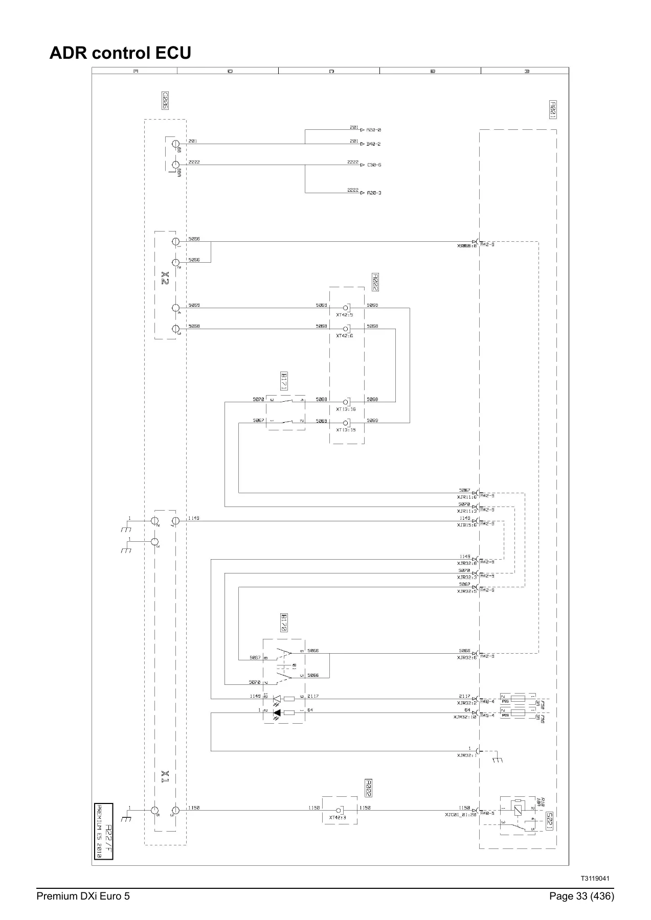
- ADR control ECU – full pinout and circuit diagram for the ADR power supply management system
- Electrical distribution – seven sheets covering the cab distribution box, after-ignition relays, accessory relays, and power supply routing
- Vehicle electronic management – VECU, throttle pedal sensors, clutch pedal sensor, cruise control, and cab tilt circuits
- Main information display and tachograph – display pinout, sensor inputs, and tachograph wiring
- FMS, DATAMAX and OPTIFLEET onboard management – telematics and fleet management interfaces
- 7-litre engine electronic management – two sheets covering sensors, injectors, engine brake, and fuel heating circuits
- 11-litre engine electronic management – two sheets covering sensors, injectors, engine brake, VTC, and cooling fan control
- Urea supply management – pump module, heating resistors, NOx sensor, and exhaust gas temperature sensors
- Differential lock – rear wheel and inter-axle differential lock circuits
- Automated manual transmission and ALLISON 3000V – gear selector, ECU, sensors, and solenoid valves
- Electrical retarder and ECOSPLIT hydraulic retarders – control units and solenoid circuits
- OptiTrack hydraulic system – sensors, solenoid valves, fan control, and diagnostic socket
- EBS braking systems – 4×2, 6×2, 6×4 and 8×4 configurations with modulator assemblies, wheel speed sensors, and trailer brake control
- Air suspension – 4×2, 6×2 and 6×4/8×4 electronic air suspension with position sensors, pressure sensors, and solenoid valve assemblies
- Steered axle – oil level sensor, steering angle sensors, and solenoid valve assembly
- Air production management – air production ECU and CAN bus wiring
- Door/immobiliser, alarm and tyre pressure monitor – central locking, engine immobiliser, alarm sensors, and tyre pressure monitoring
- Lighting and signalling – three sheets covering headlamps, direction indicators, marker lights, fog lights, work lights, and overhead lighting
- Electric windows and sunroof – window lift motors and sunroof control
- Adjustable heated door mirrors – mirror motors, heating resistors, and windscreen heating
- Comfort accessories – cigarette lighter, heated seats, refrigerator, and power sockets
- Radio – radio set, speakers, microphone, and audio connectors
- Independent heating – AT 2000 ST and THERMO 90ST systems with ECUs, sensors, and fuel pump circuits
- Air conditioning – ECU, compressor clutch, fan-coil heater motor, and pressure sensors
- Body builder pre-equipment management – PTO engagement, available power supplies, and body builder control unit
Equipment Locations
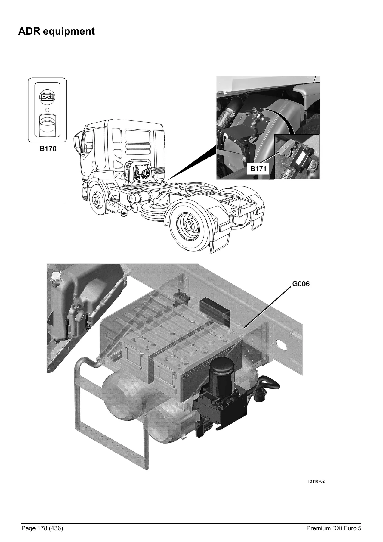
Following the wiring diagrams, the manual provides a full set of equipment location illustrations. These pages show where each component is physically mounted on the vehicle – cab, chassis, engine, gearbox, and rear axle. You get truck-level illustrations with component callouts for the ADR equipment, vehicle electronic management, urea supply system, 7-litre and 11-litre engines, OptiTrack system, air conditioning, air suspension, EBS components, steered axle, automatic gearbox, ALLISON 3000V gearbox, independent heating systems, radio, alarm, tyre pressure monitor, lighting, doors, and bodywork pre-equipment. Each location page is paired with an equipment key that lists the component code, title, and the wiring diagram page where that component appears.
Electrical Distribution
The electrical distribution section provides the fuse and relay tables for the cab distribution box. The fuse table covers every fuse from F01 through F108, listing the fuse rating in amps, the wiring diagram folio where the circuit appears, the component code, and the function title. The relay table follows the same format for relays S001 through S923, including relay item numbers, current ratings, and the circuits they control. Separate tables cover fuses and relays outside the distribution box, including the OptiTrack system relays. This section is essential for diagnosing blown fuses, identifying relay functions, and understanding power distribution across the vehicle.
Trailer Connections
The trailer connections chapter documents the X900 15-pin trailer socket and the X906 EBS 7-pin trailer socket. For each pin, the manual lists the function, the associated fuse marking, and the fuse rating. This covers trailer direction indicators, parking lamps, brake lamps, reversing lamps, fog lamps, and the 24-volt power supply after the master switch, as well as the EBS trailer socket pins for power supply, earth, ABS warning lamp, and CAN bus lines.
Available Power Supplies
This section details the available power supplies for body builders and auxiliary equipment. It covers connections inside the cab (locations PB1, PB2, PB4, PB5), on the chassis (locations 2 and 3), and the PB3 connector. Each entry lists the function title, the wire number, the fuse marking, and the rating where applicable. You get access to power take-off controls, engine speed signals, reversing information, parking brake information, gearbox neutral information, speed limitation signals, suspension level controls, alarm stop, night heater cut-off, and CAN bus J1939 high and low level connections. The manual includes a clear warning that creating take-off points on existing wiring harnesses is prohibited, and that type-approved connectors and harnesses must be used.
Connectors
The connectors chapter provides a comprehensive reference for every wiring harness on the vehicle. It is organised by harness and covers the dashboard wiring harness (14 sheets), steering column harness, battery compartment-to-cab connection harness, engine-to-cab connection harness for DXi 7 and DXi 11, cab overhead console harness, overhead console-to-anti-glare strip harness, front end harness, driver and passenger door harnesses, bumper harness, tractor chassis main harness, rigid main harness, independent heating harnesses, gearbox connection harnesses for manual, OPTIDRIVER and ALLISON gearboxes, OptiTrack harness, urea harness, and trailer connection harness. For each connector, the manual lists the component code, function title, connector marking, colour, and number of pins. The chassis-cab/bulkhead grommet connection section completes the picture with the XT02, XT12, XT13, XT14, XT22, XT32, XT33, XT42, XT53, XT54, XT55, XT56, XT62, XT63 and XT70 connectors.
Complete System Coverage for Premium DXi Euro 5
This Renault Premium DXi Euro 5 wiring diagrams manual covers the complete electrical architecture of the vehicle. Whether you are working on a 4×2 tractor unit, a 6×2 rigid, a 6×4 construction vehicle, or an 8×4 heavy hauler, the diagrams are organised by system and configuration so you can find the exact circuit you need. The manual covers both the 7-litre and 11-litre engine variants, and it includes the ADR equipment variant for hazardous goods transport. The CAN bus architecture section ties the whole vehicle network together, showing you how the ECUs communicate and where the bus transfer zones are located.
Why Technicians Choose This Wiring Diagrams Manual
Electrical faults on modern trucks are rarely simple. A single broken wire or corroded connector can trigger a cascade of fault codes across multiple systems. Without accurate wiring diagrams, you are left guessing – and guessing costs time, money and customer confidence. This manual gives you the exact wire colours, connector pin numbers, component codes, and circuit paths for every system on the Premium DXi Euro 5. You can trace a circuit from the fuse box through the harness to the component and back to earth, verifying every connection along the way. The equipment location illustrations show you where each component is physically mounted, so you spend less time searching and more time fixing. The fuse and relay tables let you quickly identify which circuit is protected by which fuse, and the connector pinout tables tell you exactly what to expect at each pin.
IMAGES PREVIEW
Instant PDF Delivery
This Renault Premium DXi Euro 5 wiring diagrams manual is delivered as an instant PDF download. No shipping, no waiting, no physical media to lose. Once payment is complete, you can download the manual and start using it immediately on your workshop computer, laptop, tablet or smartphone. The PDF format means you can zoom in on dense schematic sheets, print individual diagrams for use at the vehicle, and search for component codes or wire numbers across the entire document. Whether you are diagnosing a fault in the workshop, planning a body builder installation, or tracing a wiring issue on the roadside, this manual gives you the information you need in a format that works wherever you are.
Reviews
There are no reviews yet.