
Hino 238 258LP 268 338 358 Chassis Workshop Manual Vol. 2 of 2 – Steering, Axle, Suspension, Cab & Electrical Systems (S1-UNAE12A)
Original price was: $67.95.$44.95Current price is: $44.95.
Volume 2 of the Hino 238, 258LP, 268, 338 and 358 Chassis Workshop Manual (S1-UNAE12A) covering steering equipment and the TRW TAS65 power steering gear, MFS front axles, RS rear axles, wheel and tire, leaf and air suspension, chassis frame, cab, electrical equipment and the complete electric wire diagram set. 562-page PDF for J08E-VB and J08E-VC trucks.
Description
Volume 2 of the two-part Chassis Workshop Manual for the Hino 238, 258LP, 268, 338 and 358 series trucks – document S1-UNAE12A – picks up where Volume 1 stops and carries the chassis service story through steering, axles, suspension, cab, electrical systems and the complete electric wiring set. Written for J08E-VB and J08E-VC powered trucks in the NE8J, NF8J, NJ8J, NV8J and NH8J production codes, this is the second half of a workshop manual that Hino split at the driveline/differential boundary: Volume 1 covers clutch, transmission, propeller shaft, differential and brakes, and this volume covers everything else from the steering wheel back to the rear axle and up into the cab. At 562 pages, it is the larger of the two volumes and the one that carries the full electric wire diagram set.
File Details
- Manual type: Chassis Workshop Manual (Volume 2 of 2)
- Brand: Hino
- Models: Hino 238, 258LP, 268, 338, 358 – production codes NE8J, NF8J, NJ8J, NV8J, NH8J
- Engines: J08E-VB, J08E-VC
- Document number: S1-UNAE12A (2/2)
- Publisher: Hino Motors Sales U.S.A., Inc.
- Language: English
- Page count: 562
- File format: PDF
Chapters Covered
- Steering Equipment
- Front Axle (MFS)
- Rear Axle (RS Series)
- Wheel & Tire
- Suspension
- Chassis Frame
- Cab
- Electrical Equipment
- Electric Wire
Steering Equipment
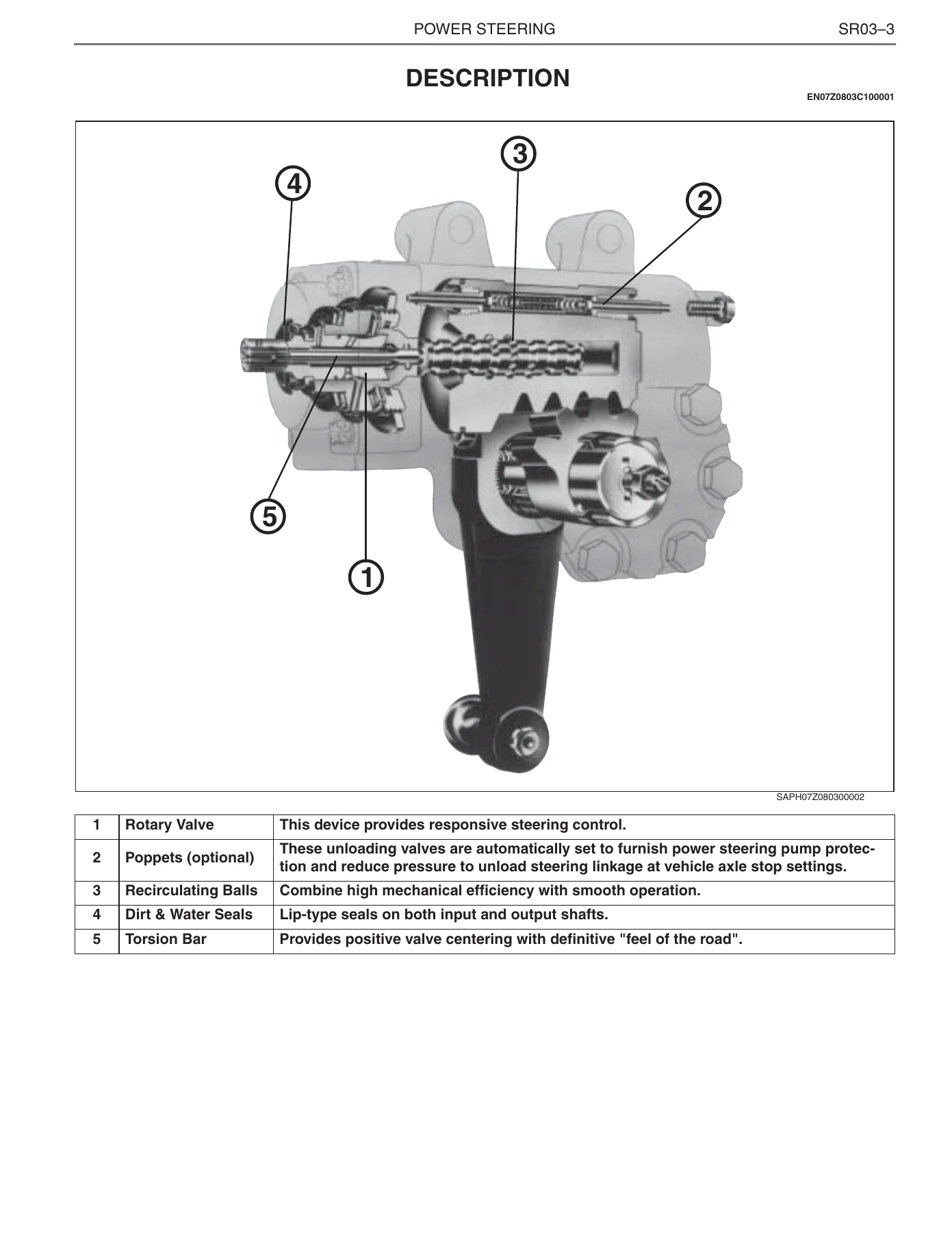
Shimmy, hard steering and poor return-to-centre diagnostics, then a full teardown of the TRW TAS65 integral hydraulic power steering gear – rotary valve, recirculating ball set, poppet valves, sector shaft adjustment, input shaft seal replacement, worm bearing preload, and the poppet re-set procedure that keeps the gear from bottoming out against the axle stops. The vane-type power steering pump gets the same treatment, with flow control valve, rotor, cam ring and vane inspection plus the approved hydraulic fluid list. Steering wheel and pitman arm removal, drag link dust seal replacement and the on-vehicle operating checks are all covered with their tightening torques, and the steering system troubleshooting chart points to the specific SR01 page for each symptom.
Front Axle (MFS)
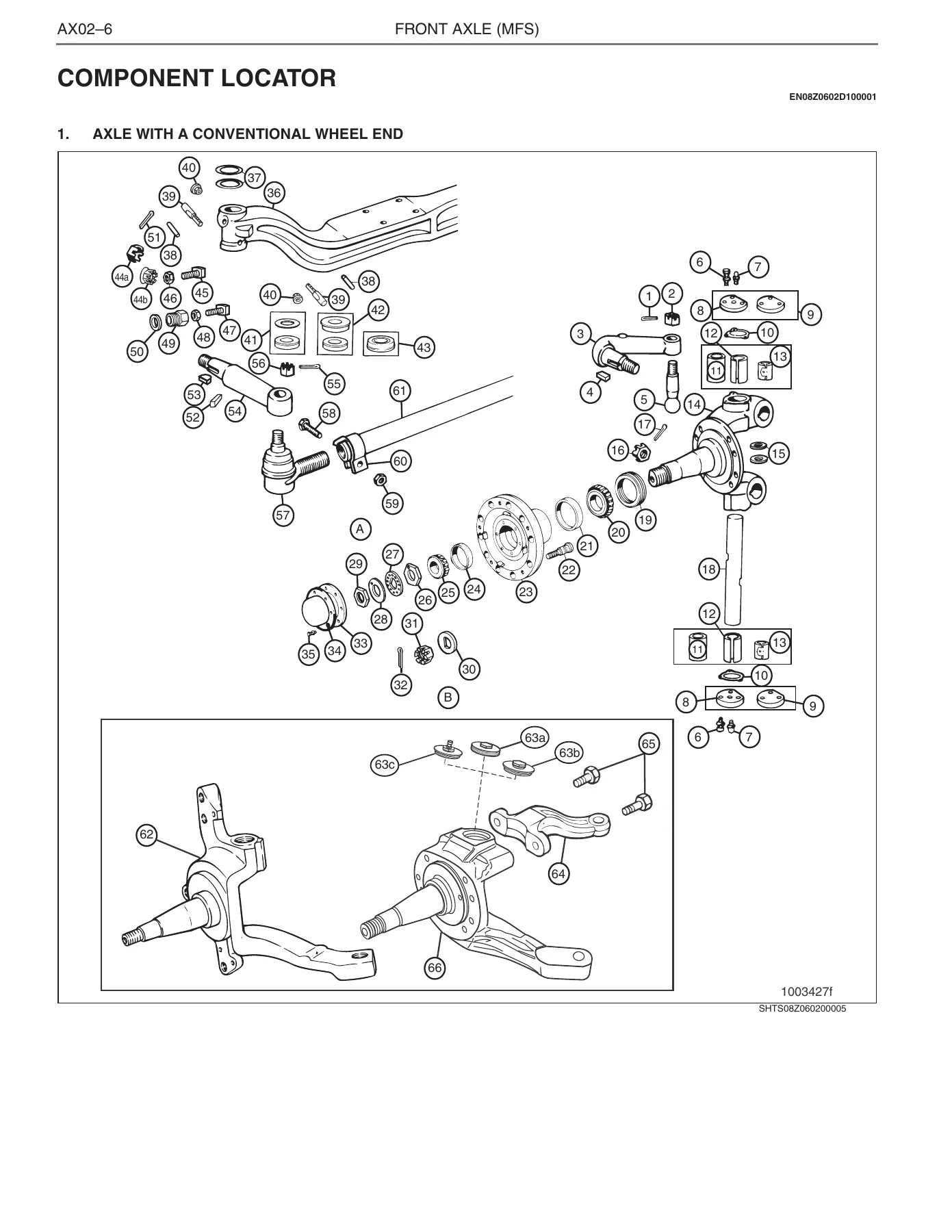
Meritor MFS-8, MFS-10, MFS-12 and MFS-14 non-drive steer axles in conventional and unitized wheel-end configurations. Steering knuckle vertical end-play measurement, king pin bushing removal and installation with and without a press, bushing reaming, king pin inclination and camber/caster checks, tie rod and cross tube inspection with the DOT 1/8-inch roadside replacement criterion, wheel bearing adjustment, and the full torque spec sheet. The axle service covers both the two-piece thrust bearing with cover-type seal and the one-piece integral thrust bearing with integrated grease seal.
Rear Axle (RS Series)
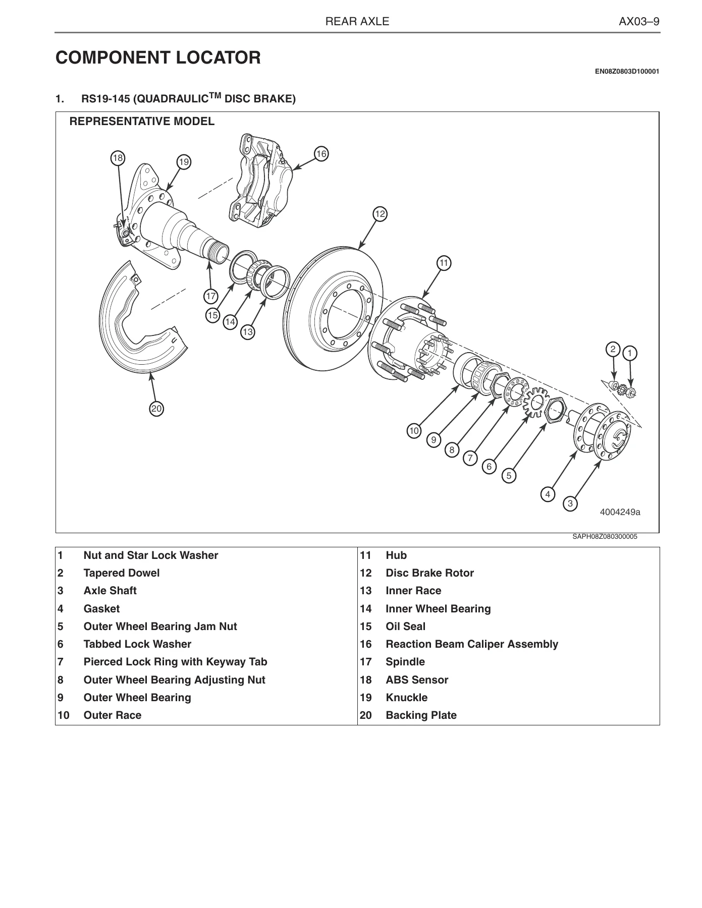
RS17-145, RS19-145, RS21-145 and RS23-160 full-floating tube axles. Wheel-end disassembly and assembly for both the Quadraulic disc brake (RS19-145) and Q Plus cam brake (RS21-145) variants – hub, rotor or drum, bearings, oil seals, bearing adjustment to 0.001-0.005 inch end play, axle shaft and tapered dowel service, stud replacement, and the oil- and grease-lubricated bearing intervals and approved lubricants. The axle identification tag, gear ratio and speed limit data tables are also included.
Wheel & Tire
Tire load and inflation tables, runout limits, static and dynamic balancing, tubeless tire disassembly and assembly with the Hino lever and rubber hammer, wheel nut torque in the diagonal sequence, and dual-tire installation notes.
Suspension
Front and rear leaf spring suspension with double-acting shock absorbers, plus the Hendrickson Comfort-Air and Comfort-Air-SD rear air suspension. Component locators, U-bolt torque, spring pin and bushing service, leaf disassembly and re-assembly, helper rubber and stabilizer bar inspection, air spring and height control valve replacement, and the vehicle-height adjustment procedure. The leaf spring centre bolt and clip bolt torques, shackle inspection and caster shim placement are all covered.
Chassis Frame
Frame inspection on a level floor with plumb-line measurement, rivet and bolt tightness checks, crack repair with V-groove preparation and welding current tables, and the reinforcement patch rules covering plug-weld hole spacing and plate thickness.
Cab
Cab dismounting and mounting, hood tilt mechanism and torsion bar service, radiator grille, door adjustment with body clearances, seat and seat belt, instrument panel removal, the HFC134a air conditioning system (refrigerant precautions, leak detection, recovery and recharge, compressor oil), windshield replacement, weatherstrip bonding, front bumper settings, and the FRP repair procedure for the hood.
Electrical Equipment
Component locator by system, relay and fuse inspection with type-1 through type-6 test procedures, gauge and warning circuits (fuel, coolant temperature, air pressure, tachometer, speedometer), lighting, turn/hazard, wiper, power door lock, power window, heater/cooler, ABS, common rail, DPR and DEF/SCR circuits, plus the speedometer pulse conversion rate table. The relay panel layout, ECU rack, instrument panel lower centre and spare power source terminal positions are shown with connector details, so you can find a relay or a spare power feed without guessing.
Electric Wire
The largest section – the full wiring diagram set for cab, chassis and engine harnesses, with specification symbol lists, connector position pages, connector pin lists for the bulkhead box and out-of-box connectors, a signal check connector pin list, and a connector list keyed by diagram symbol. This is the section you open when a chassis electrical fault needs to be traced down to a specific pin, connector and wire colour.
How the Manual is Organised
Each chapter opens with a troubleshooting table that ties symptom to possible cause and remedy, then moves through component locator, overhaul, inspection and repair in the order a technician actually works. Torque values, wear limits, clearances and adjustment values are written into the relevant steps and repeated in the chapter tables, so the book stays on the bench instead of flipping back to a central spec section. Special tools are called out where they are needed – the steering wheel puller S0965-01341 and pitman arm puller S0965-01260 in the steering chapter, for example – and the safety warnings that Hino and TRW put around high-pressure hydraulic work, spring-loaded poppets and air suspension are reproduced with the procedures.
What This Hino Chassis Workshop Manual Enables
This is the volume that covers the systems most likely to take a working truck out of service: steering that won’t centre or has play at the pitman arm, a front axle that won’t hold king pin end play, a rear wheel end leaking oil or running hot, an air suspension that won’t hold ride height, a cab that won’t align, or a chassis electrical fault that needs to be traced through the harness. The TRW TAS65 steering gear section alone – disassembly, inspection, assembly, poppet re-set and final adjustment – is the kind of content that lets a shop rebuild the gear instead of replacing it. The Meritor axle sections cover the wheel-end rebuild end to end, including bearing adjustment to 0.001-0.005 inch and the Quadraulic disc brake caliper torque figures.
Correct procedure and correct specification are what separate a repair that comes back from one that doesn’t. A poppet set wrong limits steering travel; bearing end play outside the range burns a spindle; a chassis wiring fault traced to the wrong pin wastes a day. The manual gives the actual values – 367-423 N.m on the pitman arm pinch bolt, 0.001-0.005 inch wheel bearing end play, 48 lbf.ft on the poppet fixed stop screw, 43 lbf.ft on the sector shaft jam nut – with the warnings and cautions that Hino and TRW put around them.
IMAGES PREVIEW
Delivered as an instant PDF download, no shipping and no waiting. Open it on a laptop in the shop, a tablet under the truck, or print the pages you need for the job. Every diagram, table and torque value is in the file exactly as Hino published it in S1-UNAE12A Volume 2 of 2.
Reviews
There are no reviews yet.