
Renault Trucks C Wiring Diagrams 2019 PDF – 337016/14 Electrical Schematics & Harness Manual
Original price was: $67.95.$44.95Current price is: $44.95.
Complete 722-page Renault Trucks C wiring diagrams manual (doc 337016/14, 2019) covering LIN & CAN bus architecture, shared functions, EBS, engine management, urea supply, trailer connections and full harness routing.
Description
File Details
- Manual Type: Wiring Diagrams / Electrical Schematics
- Brand: Renault Trucks
- Model: C Series
- Document Number: 337016/14
- Date: 2019
- Language: English
- Page Count: 722
- File Format: PDF
Chapters Covered
- Communication Bus Architecture
- Shared Functions
- Wiring Diagrams
- Summary of Diagrams
- Equipment Locations
- Layout of Controls
- Electrical Distribution
- Chassis-Cab/Bulkhead Grommet Connection
- Trailer Connections
- Available Power Supplies
- Wiring Harnesses
- Cab Inter-Connectors
- Chassis Inter-Connectors
Communication Bus Architecture
The opening section maps every data network used across the Renault Trucks C range. You get the LIN BUS architecture with a complete device key listing every ECU, sensor and control unit by code, function and location. The CAN BUS architecture is split into two dedicated sub-sections: Euro III and Euro V with ACM 1.0, and Euro V and Euro VI with ACM 2.0. Each includes its own device key, so you can trace which module sits on which bus, at which location, and under which emissions variant. This is the starting point for any electrical diagnosis on these vehicles – without it, you are guessing which network carries the fault.
Shared Functions
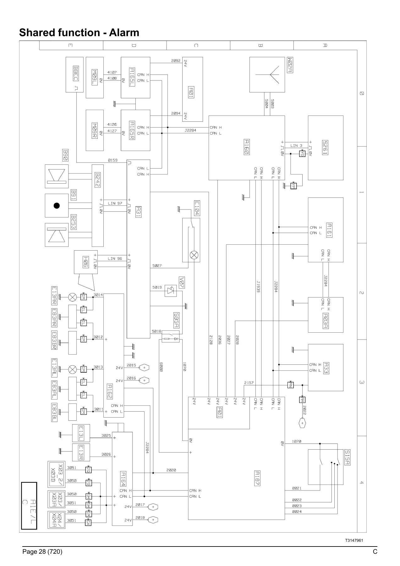
This is the largest and most practical portion of the manual. It breaks the vehicle down into 30+ shared function sheets, each showing the main equipotentials, communication buses and equipment affecting that function. Covered functions include distribution and management of electrical power (both without ADR and with ADR), display, locking/unlocking of doors, alarm, interior lighting, external lighting, immobiliser, Euro III and V anti-pollution, Euro VI emissions, air production management, air conditioning, mechanical and air suspension, windscreen wiper and washer, electric rear-view mirrors, safety and driving assistance, braking management, trailer-specific braking management, engine management (split by ACM 1.0 and ACM 2.0), transmission, automated manual transmission management, retarder, tachograph, windows and sunroof, front braking management, and rear braking management. Each sheet tells you which diagram page to turn to for the detailed electrical operation – making this section a genuine index and overview at the same time.
Wiring Diagrams
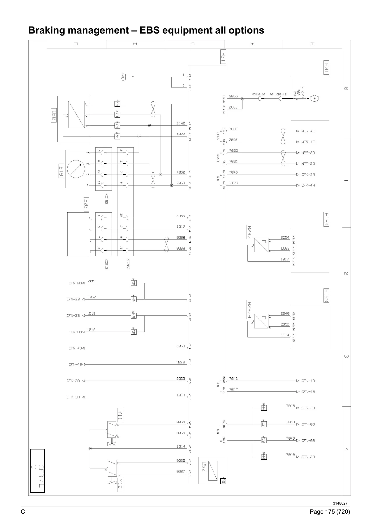
The core of the manual: hundreds of individual wiring diagrams that show the conventional electrical operation of every circuit on the vehicle. Diagrams cover the 11-litre and 13-litre engine platforms across Euro III, Euro V and Euro VI standards. You get engine management schematics (EECU pinouts, sensor and actuator circuits), injection control diagrams for both engine sizes, urea supply diagrams for Euro V (ACM 1.0 and ACM 2.0) and Euro VI (phase 1 OBDEP-A, phase 2 OBDEP-C, phase 3 OBDEP-D), retarder circuits (hydraulic retarder on mechanical gearbox and on automated manual transmission), EBS equipment diagrams for all axle configurations (4×2, 6×2, 6×4, 8×4, TAG axle), suspension management, lift axle management, controlled axle management, tyre pressure monitoring, differential lock, OptiTrack hydraulic system, power take-off, and trailer EBS modules. Each sheet shows wire colours, connector references, component codes and signal paths – exactly what you need to trace a fault from one end of the vehicle to the other.
Equipment Locations
Before you can repair a circuit, you need to know where components physically sit on the vehicle. This section provides location overviews for the distribution box, main information display, tachograph, engine-mounted components (11-litre and 13-litre across all emissions standards), fuel management, urea supply, telematics, steering, energy production, air production, gearbox management, braking management, suspension management, tyre management, differential lock, OptiTrack, power take-off, door management, safety systems, bodywork pre-equipment, air conditioning, night-time air conditioning, radio, sunroof, heated seats, windscreen de-icing, driving assist, video surveillance, and interior/exterior lighting. Each item is referenced to a diagram page number so you can move straight from location to circuit.
Layout of Controls
Two dedicated layout sheets show the physical arrangement of switches on the dashboard and on the overhead ledge. Every switch is identified by its device code (S95A, S227, S243, S244, S245, S264, S266, S268, S277, S278, S279, S280, S901, S38, S77, S210, S238, S261), with a function description and the diagram page where its circuit is drawn. This is useful when a switch panel has been removed or when you need to confirm which control operates which function.
Electrical Distribution
Full fuse and relay tables are provided for the cab electrical distribution box, plus tables for fuses outside the distribution box, fuses for the OptiTrack system, and relays outside the box. Each entry gives the fuse or relay code, current rating in amps, the folio reference, and the component code with function description. The section also includes Face A and Face B connector pinouts for the electrical distribution box, listing pin number, designation, polarity number and diagram page. If you are chasing a blown fuse or a faulty relay, this section saves you from pulling every fuse in the box.
Chassis-Cab/Bulkhead Grommet Connection
This section documents the connectors that pass through the bulkhead between the cab and chassis. Connectors XC201 through XC213 are listed with pin number, designation, polarity number and diagram page. This includes the 1939 CAN bus, 2284 CAN bus for chassis, wheel steer angle sensor signals, brake pedal signals, LIN bus for electric parking brake and independent heating, and the main power supplies that cross between cab and chassis. This is the section you need when a circuit works inside the cab but not on the chassis side.
Trailer Connections
Pinout tables for every trailer socket variant: X02, X02A, X02_2, X02B (7-pin ABS/EBS), X03, X03A, X03_2, X03B (15-pin), X04, X04A (7-pin type 24 N), and X05, X05A (7-pin type 24 S). Each pin is identified with its designation, polarity number and diagram page. Trailer lighting circuits, EBS CAN bus signals, bodybuilder pre-equipment signals and power supplies are all covered.
Available Power Supplies
Location-by-location documentation of the power take-off points Renault Trucks provides for bodybuilders and accessory installation. Covers available supplies inside the cab (locations 1 through 9), at bodybuilder pre-equipment locations BBEC1A, BBEC2A and BBEC3A, and on the chassis (locations 1 and 2, plus BB1, BB2 and BB3). Each entry gives the function description, polarity number, connector marking and current rating. This section also includes the warning that all electrical connections must be made on the supplies provided by Renault Trucks, and that creating a take-off point on the wiring harnesses is prohibited.
Wiring Harnesses
Harness routing diagrams with connector code, function description, connector colour and pin count for every major harness on the vehicle: electrical distribution, main CAN bus J1939, information display, tachograph, 11-litre engine (Euro III, Euro V, Euro VI), 13-litre engine (Euro III, Euro V, Euro VI phase 1, and phase 2/3), urea supply (Euro V, Euro VI phase 1/2, Euro VI phase 3), telematics, mechanical gearbox, automated manual transmission (Euro V and Euro VI), S4000 and S4500 automatic gearbox, EBS equipment, suspension, door harness (before and after 2017/06/05), alarm, air conditioning, audio system (before and after 2017/06/05), accessories, windscreen de-icing, driving assist (before 2018/06/04 and after 2018/06/03), cab tilt, cab interior lighting, cab external lighting, chassis exterior lighting (main beam and on-site headlights), windscreen wiper/washer, and controls. This lets you identify the correct harness before ordering or repairing.
Cab and Chassis Inter-Connectors
The final reference sections list every inter-connector in the cab and on the chassis. Cab inter-connectors include BBEC1A, BBEC2A, BBEC3A, XC110, XC136 through XC140, XC146, XC148, XC156, XC158, XC160 through XC178, XC180, XC181, XC183 through XC191, XC193 through XC198, XC214, XC215, XC216 and XC900. Chassis inter-connectors include XC301, XC302, XC303, XC312 through XC323, XC325, XC327, XC328, XC330 through XC332, XC342, XC351, XC355, XC357, XC359 and XT65. Each table gives pin number, designation, polarity number and diagram page. When a connector is damaged or you need to confirm a pinout, this is where you find it.
Why This Manual Matters
The Renault Trucks C wiring diagrams manual 337016/14 is not a generic schematic collection – it is the complete electrical reference for the C range as produced in 2019. Every diagram, pinout, fuse rating and harness route is specific to these vehicles. Whether you are diagnosing an EBS fault on a 6×2 tractor, tracing a LIN bus failure on a Euro VI engine, repairing a door harness, fitting bodybuilder equipment to the pre-equipped power supplies, or confirming trailer socket wiring before a test, the correct procedure and the correct reference are here. The manual covers the full spread of emissions variants – Euro III, Euro V with ACM 1.0 and ACM 2.0, and Euro VI phases 1, 2 and 3 – so you are not forced to guess whether a circuit differs between standards. The fuse and relay tables alone can cut diagnostic time dramatically, and the connector pinouts remove the guesswork from continuity testing. For any workshop maintaining Renault Trucks C vehicles, this wiring diagram PDF is the single most useful electrical document you can have open on the screen.
IMAGES PREVIEW
Instant PDF Delivery
The manual is delivered as a PDF download immediately after payment. No shipping, no waiting, no physical media. You can open it on any device – laptop, tablet or phone – and print the specific diagram pages you need for the job. Keep it on the workshop computer, load it onto a diagnostic tablet, or print a harness routing page and take it under the vehicle. When you are mid-diagnosis and need the EBS pinout or the urea supply circuit, the file is already there.
Reviews
There are no reviews yet.