
Renault Trucks K Wiring Diagrams Manual 2019 PDF – Complete Electrical Service Guide
Original price was: $65.95.$40.95Current price is: $40.95.
Complete 666-page Renault Trucks K wiring diagrams manual (doc 337017/17, 2019). Covers Euro III, Euro V and Euro VI electrical systems, communication buses, shared functions, fuse and relay tables, connector pinouts, harness routing and component locations.
Description
Renault Trucks K Wiring Diagrams Manual — 337017/17 (2019)
This is the complete Renault Trucks K wiring diagrams manual, document number 337017/17, published in 2019. It covers the full electrical architecture of the K range, including communication bus systems, shared functions, and detailed circuit diagrams for every major vehicle system. At 666 pages, it is the definitive electrical reference for these trucks.
File Details
- Manual type: Wiring Diagrams / Electrical Service Manual
- Brand: Renault Trucks
- Model: K series
- Document number: 337017/17
- Year: 2019
- Language: English (with multilingual information notes)
- Page count: 666 pages
- File format: PDF
Chapters Covered
- Communication Bus Architecture
- Shared Functions
- Wiring Diagrams
- Equipment Locations
- Layout of Controls
- Electrical Distribution
- Trailer Connections
- Available Power Supplies
- Wiring Harnesses
- Cab Inter-Connectors
- Chassis Inter-Connectors
Communication Bus Architecture
The manual opens with a full breakdown of the vehicle’s communication networks. It covers the LIN BUS architecture and the CAN BUS architecture across three generations of emissions standards: Euro III and Euro V with ACM 1.0, Euro V and Euro VI with ACM 2.0, and the Euro VI variants. Each bus section includes a device key with function codes, locations, and diagram page references, so you can trace any ECU or sensor back to its place in the network. The J1939 and J2284 CAN bus transfer zones are also documented, giving you the full data communication map for the vehicle.
Shared Functions
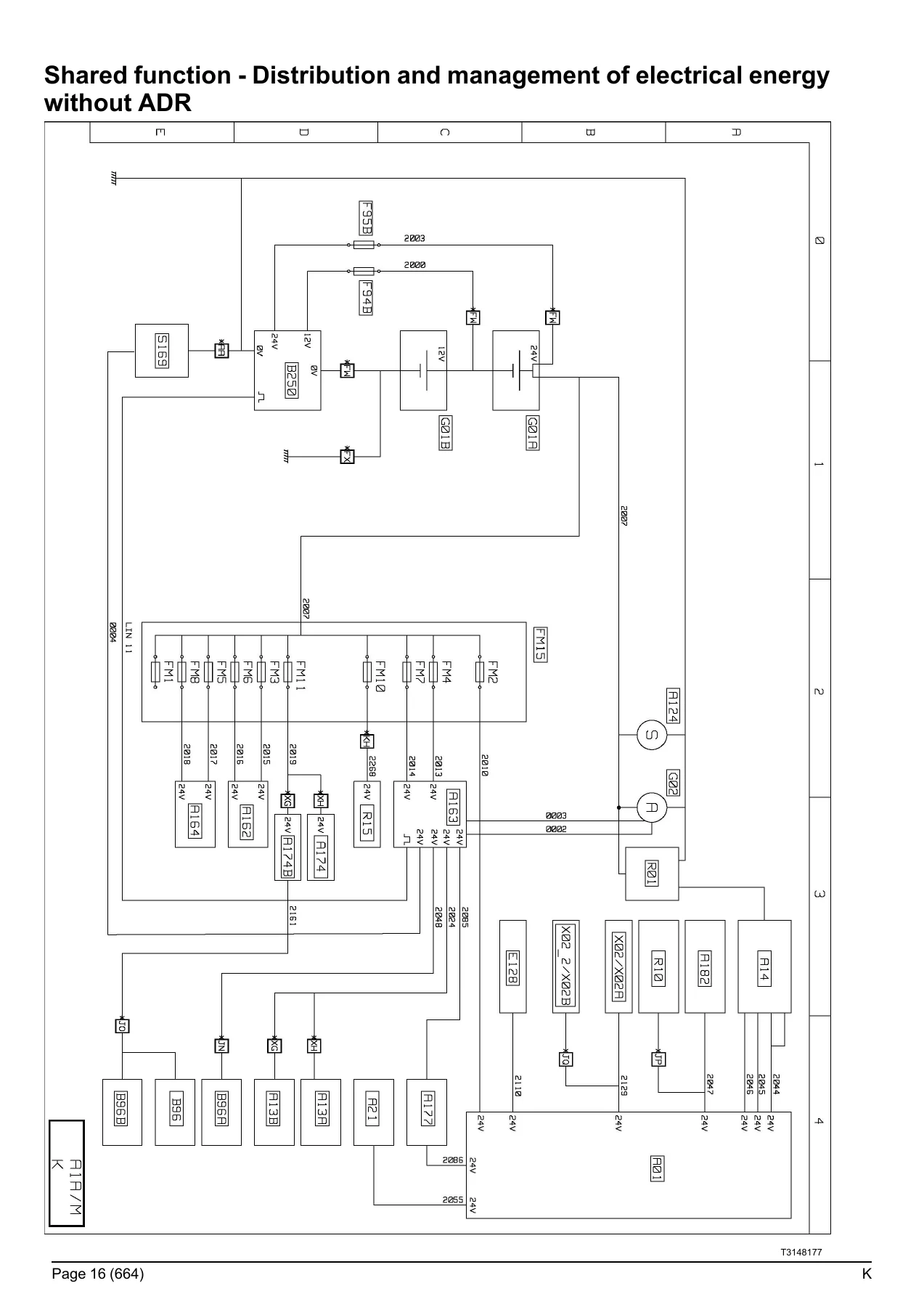
This section presents the top-level equipotential diagrams for every major vehicle function. Rather than diving straight into individual circuits, these diagrams show the overall system architecture — power distribution, communication buses, and the equipment involved in each function. You get shared function diagrams for electrical power distribution (with and without ADR equipment), display systems, door locking and unlocking, alarm, interior and exterior lighting, immobiliser, anti-pollution systems for Euro III, Euro V, and Euro VI, air production management, air conditioning, windscreen wiper and washer, electric rear-view mirrors, safety and driving assistance, braking management (including trailer-specific braking), engine management, transmission, automated manual transmission management, retarder, tachograph, and windows and sunroof. Each shared function is accompanied by a detailed device key with codes, titles, locations, and diagram page references.
Wiring Diagrams
The core of the manual is the wiring diagram section, which covers the entire vehicle system by system. You’ll find complete circuit diagrams for:
- Energy production and electrical distribution — standard production, ADR equipment, and chassis distribution
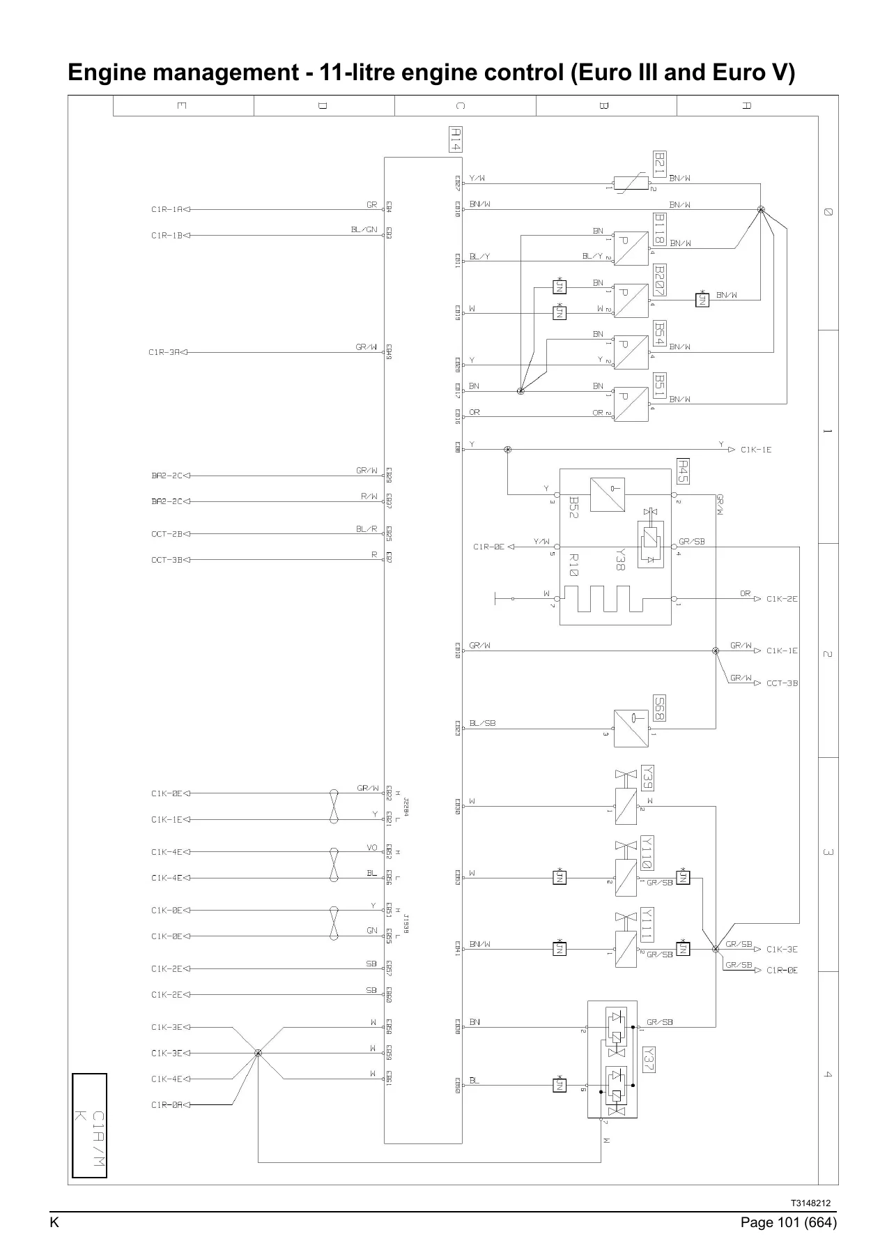
- Starting and engine management — 11-litre and 13-litre engine control for Euro III, Euro V, and Euro VI (including Phase 1 OBDEP-A, Phase 2 OBDEP-C, and Phase 3 OBDEP-D), injection control, fuel heating, and engine preheating
- Urea solution supply — Euro V with ACM 1.0 and ACM 2.0, Euro VI Phase 1, 2, and 3
- Vehicle management — main ECU, main information display, tachograph, fleet management pre-equipment and telematics
- Gearbox management — ALLISON S4000 and S4500 automatic gearbox, automated manual transmission (AMT), and manual gearbox
- Driveline and retarder — differential lock, transfer box, and hydraulic retarder
- Braking management — EBS equipment for all options, front EBS module, rear EBS module, brake pad wear sensors, and trailer EBS module
- Tyre pressure monitoring
- Suspension management — mechanical suspension and power-assisted steering
- Safety and security — immobiliser, door management (left and right), alarm, video surveillance, and alcotest
- Lighting and signalling — headlights, rear lights, side parking lights, roof-mounted parking lights, and horn
- Washing and wiping — windscreen wiper and washer
- Driving assist — driving radar
- Life on board — cab compartment lighting, independent heating (air/air and air/water), air conditioning, heated seats, windscreen de-icing, sunroof and sun visor, audio system, entertainment and service module, TV/DVD, 12V sockets and accessories, and control/command systems
- Vehicle maintenance — cab tilt and hour meter
- Trailer connections — rigid, tractor, and dual-type trailer sockets
- Body builder system management — pre-equipment ECU, main ECU, central chassis ECU, electrical distribution box, supplementary lighting, and Crew CAB
Every diagram is supported by a comprehensive device key that lists component codes, descriptions, locations, and cross-references to other diagram pages, making it straightforward to trace any circuit from source to load.
Equipment Locations
Knowing where components physically sit on the vehicle is essential for efficient diagnosis and repair. This section provides detailed location layouts for the distribution box, main information display, tachograph, and the electronic management systems for both the 11-litre and 13-litre engines across all emissions standards. You’ll also find the layout of equipment on the engine itself — sensors, actuators, and control units — plus fuel management, urea supply management, and body builder pre-equipment layouts. The location diagrams are referenced by the same component codes used throughout the wiring diagrams, so you can move seamlessly between circuit tracing and physical location.
Layout of Controls
This section shows the physical layout of switches on the dashboard and overhead ledge, with each control identified by its code and linked to the relevant diagram page. It covers the cab air conditioning control panel, alarm panic button, fuel heating control, body builder pre-equipment controls, repositionable control units (groups 1, 2, 3, and 5), external lighting control unit, cruise control assembly, differential lock selector, cab lighting control, vehicle emergency stop controls, emergency call control, roof identification light control, and passenger side front curtain control.
Electrical Distribution
The electrical distribution section is a complete reference for the vehicle’s power supply infrastructure. It includes:
- Fuse tables — full listing of fuses on the electrical distribution box, with fuse number, amperage rating, circuit code, and the components each fuse protects
- Relay tables — complete relay listing with relay number, amperage rating, and the circuits and components each relay controls
- Fuses and relays outside the distribution box — additional protection devices located elsewhere on the vehicle
- Connector pinouts — detailed pin-by-pin breakdown of Face A and Face B connectors on the electrical distribution box, with designation, polarity number, and diagram page reference for every pin
This section is invaluable for troubleshooting electrical faults, identifying which fuse or relay protects a specific circuit, and understanding the power distribution architecture of the K series.
Trailer Connections
Complete pinout documentation for all trailer socket types used on the K range: 7-pin ABS/EBS trailer sockets (standard, dual-use variants), 15-pin trailer sockets (standard, dual-use variants), 7-pin type 24 N trailer connections, and 7-pin type 24 S trailer connections. Each pinout lists the pin number, designation, polarity number, and diagram page reference, so you can correctly wire or diagnose any trailer connection configuration.
Available Power Supplies
This section documents all available power supply points on the vehicle, both inside the cab and on the chassis, for connecting additional equipment or body builder systems. It lists the location, function, polarity number, connector marking, and amperage rating for each supply point, including available power supplies at the cab inter-connectors (XC209, XC184, XC178, XC181, XC191, XC189), body builder pre-equipment connectors (BBEC1A, BBEC2A, BBEC3A), and chassis connectors (XC351, XC198, BB1, BB2, BB3). This is essential for anyone adding auxiliary equipment, telematics systems, or body builder installations.
Wiring Harnesses
Understanding how the wiring harnesses are routed through the vehicle is critical for effective troubleshooting and repair. This section provides comprehensive harness routing information, including the electrical distribution harness, main CAN bus harness (J1939), information display harness, tachograph harness, engine harnesses (11-litre and 13-litre, Euro III, Euro V, and Euro VI), urea supply system harnesses, telematics management harness, gearbox harnesses (manual, automated manual transmission, and ALLISON automatic), EBS equipment harness, door harnesses, alarm harness, air conditioning harness, audio system harness, accessories harness, windscreen de-icing harness, driving assist harness, cab tilt harness, interior and exterior lighting harnesses, windscreen wiper and washer harness, and controls harness. Each harness entry lists the connector code, connector colour, and pin count, giving you a clear picture of the harness architecture.
Cab and Chassis Inter-Connectors
The final sections provide complete pinout data for all cab inter-connectors and chassis inter-connectors. This includes the BBEC1A, BBEC2A, BBEC3A body builder connectors, XC110 through XC900 cab connectors, and XC301 through XT65 chassis connectors. Each pinout lists the pin number, designation, polarity number, and diagram page reference. These inter-connector pinouts are essential when tracing circuits between the cab and chassis, or when diagnosing faults at harness junctions.
Why This Wiring Diagrams Manual Matters
Electrical faults are among the most time-consuming and frustrating problems to diagnose on any modern commercial vehicle. The Renault Trucks K series is a complex machine with multiple communication networks, dozens of electronic control units, and hundreds of circuits. Without accurate wiring diagrams, even a simple fault can turn into hours of guesswork. This manual eliminates that guesswork. It gives you the exact circuit paths, connector pinouts, fuse and relay assignments, and component locations you need to diagnose electrical faults correctly and efficiently.
Whether you’re troubleshooting a non-starting engine, a lighting fault, a communication bus error, a braking system issue, or a body builder installation problem, this manual provides the diagrams and data to get the job done right. It covers every emissions standard — Euro III, Euro V, and Euro VI — so you can use it on a wide range of K series vehicles. The device keys and cross-references make it easy to navigate from a symptom to the relevant circuit, and from the circuit to the physical location of the component.
IMAGES PREVIEW
Instant PDF Delivery
This Renault Trucks K wiring diagrams manual is delivered as an instant PDF download. No shipping, no waiting, no physical media. After checkout, you can access the file immediately and view it on any device — laptop, tablet, or smartphone. Need a paper copy for the workshop? Print the pages you need, whenever you need them. The PDF format keeps all 666 pages organised and accessible, so you can search for a specific diagram or component code and get straight to the information you need.
This is the same wiring diagram manual used by professional technicians and workshops, now available to you as a convenient PDF. Don’t waste time with incomplete diagrams or guesswork — get the complete Renault Trucks K electrical reference and diagnose with confidence.
Reviews
There are no reviews yet.