★ TRUSTED BY 321,897+ PROFESSIONALS WORLDWIDE
🏢
Trusted Business
Verified & Licensed
🛡️
Virus Free Files
100% Safe Downloads
🔒
Secure Payment
SSL Protected
Instant Delivery
Available Immediately
Sale!

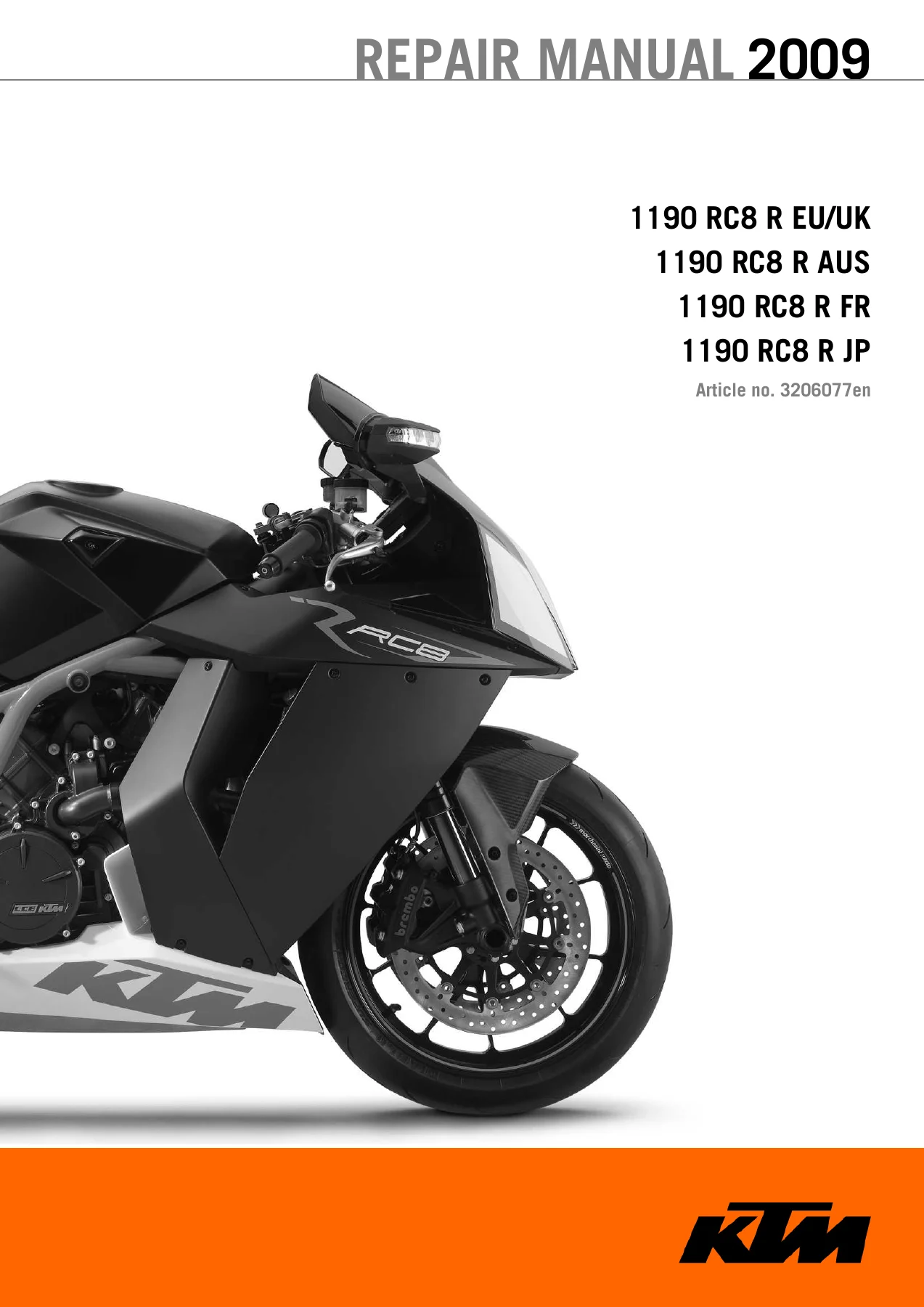
2009 KTM 1190 RC8 R Repair Manual

Original price was: $39.95.Current price is: $24.95.

Official factory 2009 KTM 1190 RC8 R repair manual covering EU/UK, AUS, FR, and JP models. Features 460 pages of detailed workshop procedures, full LC8 engine rebuild instructions, WP suspension service, Keihin EFI diagnostics, and electrical schematics.

Instant PDF Download
Available immediately
💾
Save to Your Device
Download & keep forever
🛡️
Antivirus Scanned
100% virus-free
🌍
Trusted Worldwide
175,000+ customers

Description

Comprehensive Workshop Reference: 2009 KTM 1190 RC8 R Repair Manual

The 2009 KTM 1190 RC8 R Repair Manual is the official, comprehensive workshop service resource engineered specifically for professional motorcycle technicians, race teams, and dedicated track enthusiasts servicing KTM’s flagship V-twin superbike. Covering all global production specifications including the 1190 RC8 R EU/UK, 1190 RC8 R AUS, 1190 RC8 R FR, and 1190 RC8 R JP models, this 460-page master technical publication provides exhaustive, factory-authorized service guidelines. From complete powertrain overhauls and electronic fuel injection diagnostics to competition-grade suspension tuning and chassis geometry setup, this repair manual delivers step-by-step instructions substantiated by exact workshop tolerances, tightening torques, and proprietary KTM service procedures.

Whether you are performing routine trackside maintenance, synchronizing throttle bodies, calibrating the electronic immobilizer, or completely rebuilding the high-compression 1195cc LC8 powertrain from the bare crankcases up, the 2009 KTM 1190 RC8 R Repair Manual supplies the authoritative technical data required to maintain peak racing performance and mechanical integrity. Every system is broken down with crystal-clear assembly schematics, numbered procedural steps, diagnostic flow charts, and specific specialty tool requirements.

Technical Document Details & Specifications

  • Document Title: KTM 1190 RC8 R Repair Manual 2009
  • Article / Publication Number: 3206077en
  • Manufacturer: KTM-Sportmotorcycle AG (Mattighofen, Austria)
  • Manual Type: Factory Workshop Service & Repair Manual
  • Applicable Model Year: 2009
  • Covered Model Variants: 1190 RC8 R EU/UK, 1190 RC8 R AUS, 1190 RC8 R FR, 1190 RC8 R JP
  • Engine Platform: KTM LC8 75-degree V-twin 4-stroke liquid-cooled engine
  • Document Language: English
  • Page Extent: 453 numbered pages
  • Format: Digital PDF document

In-Depth System Coverage & Workshop Procedures

The technical depth of the 2009 KTM 1190 RC8 R Repair Manual spans every mechanical, hydraulic, and electrical assembly of the motorcycle. The manual details specialized workshop disciplines that go far beyond standard owner handbooks:

Engine Teardown, Component Inspection & Overhaul

Detailed step-by-step procedures guide the technician through full removal, disassembly, precision measurement, and blueprint reassembly of the LC8 powerplant. Critical procedures include locking the crankshaft at Top Dead Center (TDC) for rear and front cylinders using special tool 61229015000, camshaft removal and valve timing verification using factory timing gauges (69129130000 and 69129030000), cylinder head servicing, and valve spring compression. The manual provides precise tolerances for valve guides (6.004 to 6.016 mm, wear limit 6.050 mm), valve stem run-out (0.05 mm), valve face run-out (0.016 mm new, 0.030 mm limit), and valve clearances at 20 degrees Celsius (intake: 0.10 to 0.15 mm; exhaust: 0.25 to 0.30 mm) adjusted via precision under-bucket shims.

The bottom-end section provides complete instructions for splitting the engine crankcase, removing the balancer shaft, and servicing the crankshaft. Plain main bearing shells and connecting rod bearings are matched using factory color classifications (yellow, blue, and red) according to crank journal micrometer measurements. Connecting rod radial bearing clearance is verified using Plastigauge strips (specifying 0.030 to 0.060 mm new, 0.080 mm wear limit) with multi-stage torque-angle tightening (Step 1: 25 Nm, Step 2: 30 Nm, Step 3: 90 degrees). Cylinder barrels and forged pistons are categorized into Size I and Size II tolerances with a tight mounting clearance of 0.015 to 0.057 mm and ring end gap inspection (limit 0.50 mm). Furthermore, the triple-rotor lubrication system—comprising the main pressure force pump, middle suction pump, and left suction pump—is thoroughly detailed with rotor-to-case and axial clearance specifications.

Slipper Clutch & 6-Speed Transmission Service

The transmission and driveline chapters provide comprehensive exploded views and service steps for the anti-hopping slipper clutch assembly, clutch pressure booster mechanism, primary drive gear (M33LHx1.5 left-hand thread tightened to 130 Nm), and hydraulic master/slave actuation cylinder. Complete benchtop teardown and assembly instructions are provided for both the mainshaft and countershaft gear clusters, detailing needle bearing replacements, shift dog inspection, stop disk orientations, and shift fork blade thickness limits (4.85 to 4.95 mm).

WP Competition Suspension & Geometry Adjustment

The suspension sections detail complete overhaul, oil replacement, and multi-stage clicker baseline settings for the 43 mm WP upside-down front forks and WP rear monoshock. Fork procedures cover cartridge extraction, DU bushing replacement (utilizing outer tube preheating to 50 degrees Celsius), seal installation, and refilling with 520 ml of SAE 5 fork oil per leg. The rear WP damper instructions include full disassembly, shim stack reorganization, bleeding via professional vacuum pump station to 4 mbar, floating piston depth positioning, and nitrogen reservoir pressurization to exactly 10 bar (145 psi). Baseline damping setups are itemized across Comfort, Standard, Sport, and Full Payload configurations.

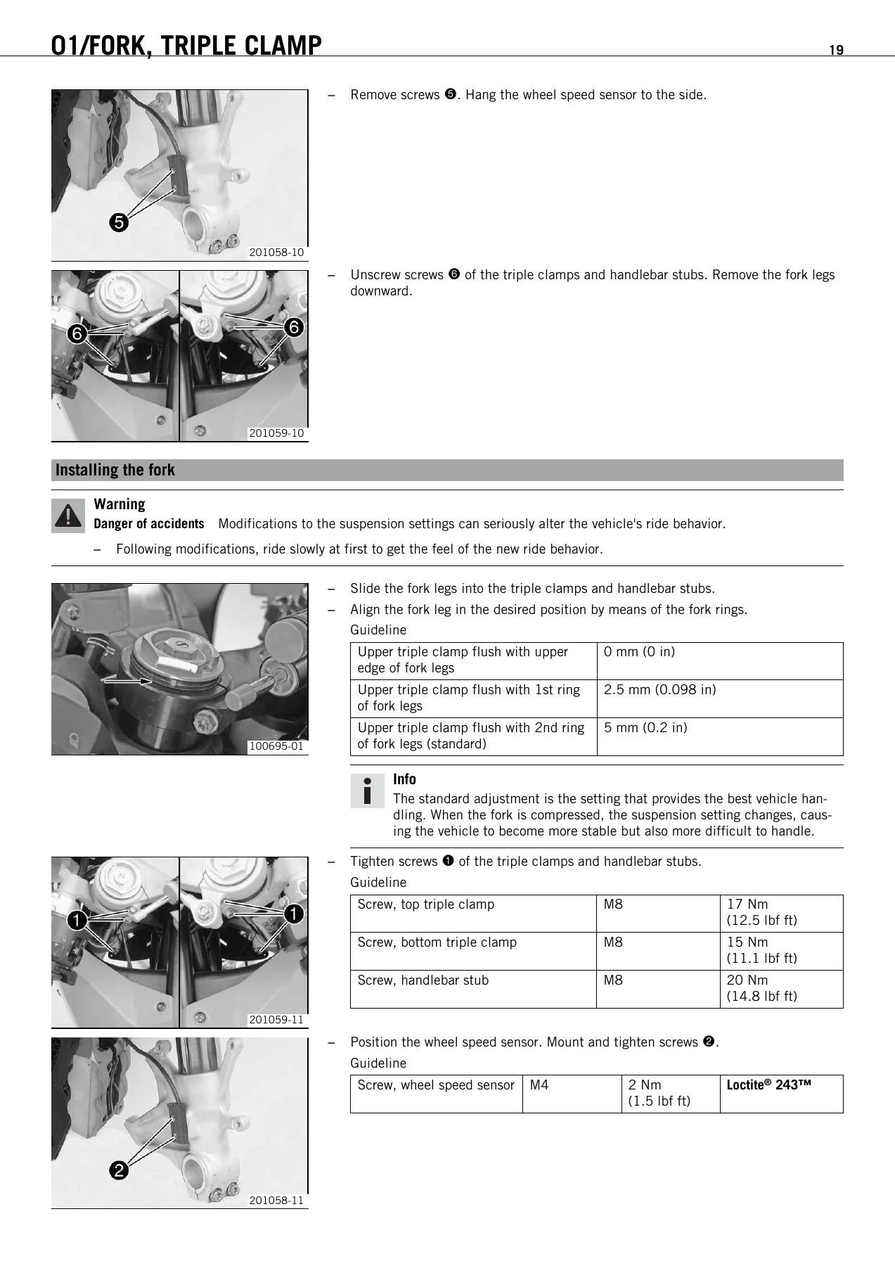
Uniquely detailed in this 2009 KTM 1190 RC8 R Repair Manual are the advanced chassis adjustability systems: three-position front fork clamping (0 mm flush, 2.5 mm 1st ring, 5 mm 2nd ring standard), 180-degree eccentric ride height adjuster offering 12 mm of rear frame height variation, two-position bolt-on rear subframe yielding seat heights of 805 mm or 825 mm, multi-position footrest brackets, and adjustable handlebar clamp heights utilizing 15 mm distance sleeves. Technicians can also interchange the throttle cam between the linear progressive profile (marking 3081) and the soft-response cam (marking 5209) with corresponding cable slack adjustment.

Complete PDF Bookmark Tree

Complete Bookmarks

The complete bookmarks in the “2009 KTM 1190 RC8 R Repair Manual” are as follows:

HOME
MEANS OF REPRESENTATIONp. 8
IMPORTANT NOTESp. 9
LOCATION OF SERIAL NUMBERSp. 10
Vehicle identification number/type labelp. 10
Key numberp. 10
Engine numberp. 10
Fork part numberp. 10
Shock absorber part numberp. 10
Steering damper part numberp. 11
MOTORCYCLEp. 12
Jacking up motorcycle frontp. 12
Taking front of motorcycle off work standp. 12
Jacking up the motorcycle in the middle (screw-in type)p. 12
Removing the motorcycle from the work stand (screw-in type)p. 13
Jacking up the motorcycle in the middle (insertable type)p. 14
Removing the motorcycle from the work stand (insertable type)p. 14
Jacking up motorcycle at the rearp. 15
Taking the rear from the workstandp. 15
Startingp. 15
01/FORK, TRIPLE CLAMPp. 17
Adjusting the compression damping of the forkp. 17
Adjusting the rebound damping of the forkp. 17
Adjusting the spring preload of the forkp. 18
Bleeding fork legsp. 18
Vehicle levelp. 19
Adjusting front vehicle levelp. 19
Removing the forkp. 20
Installing the forkp. 21
performing a fork servicep. 23
Disassembling the fork legsp. 23
Disassembling the outer tubesp. 26
Checking the fork legsp. 27
changing the lower DU bushp. 28
Assembling the outer tubesp. 29
Assembling the fork legsp. 29
02/HANDLEBAR, CONTROLS AND INSTRUMENTSp. 34
Adjusting basic position of clutch leverp. 34
Adjusting the steering damperp. 34
Adjusting the handlebar heightp. 34
Adjusting the play in the throttle cablep. 35
Throttle gripp. 36
Changing the throttle gripp. 36
Adjusting the throttle cable at the throttle valvep. 39
03/FRAMEp. 42
Side stand switchp. 42
Footrest positionp. 42
Adjusting footrest positionp. 42
Rear frame positionp. 43
Adjusting the rear frame positionp. 43
04/SHOCK ABSORBER, SWINGARMp. 46
Adjusting the low-speed compression damping of the shock absorberp. 46
Adjusting the high-speed compression damping of the shock absorberp. 46
Adjusting the rebound damping of the shock absorberp. 47
Adjusting the spring preload of the shock absorberp. 47
Adjusting the vehicle level at the rearp. 48
Removing the shock absorberp. 48
Installing the shock absorberp. 49
Servicing the shock absorberp. 50
Removing the springp. 50
Disassembling the damperp. 51
Disassembling the piston rodp. 52
Checking the damperp. 53
Assembling the piston rodp. 54
Assembling the damperp. 55
Bleeding and filling the damperp. 57
Filling the damper with nitrogenp. 60
Installing the springp. 61
Removing the heim jointp. 61
Installing the heim jointp. 62
05/EXHAUSTp. 64
Lambda sensorp. 64
Lambda sensor heaterp. 64
Removing the exhaust cover completelyp. 65
Installing the exhaust cover completelyp. 65
Removing the exhaust systemp. 65
Installing the exhaust systemp. 67
06/AIR FILTERp. 69
Removing the air filterp. 69
Installing the air filterp. 69
Removing the filter box bottomp. 69
Installing the filter box bottomp. 70
07/FUEL TANK, SEAT, TRIMp. 72
Removing the seatp. 72
Fitting the seatp. 72
Removing the passenger seatp. 72
Mounting the passenger seatp. 72
Dismounting the fuel tankp. 72
Installing the fuel tankp. 73
Removing the fuel tank guardp. 74
Installing the fuel tank guardp. 75
Checking the fuel pressurep. 75
Checking the fuel pressure during the actuator testp. 76
08/MASK, FENDER, DECALp. 77
Removing the side coversp. 77
Installing the side coversp. 77
Removing the inside coverp. 77
Installing the inside coverp. 78
09/FRONT WHEELp. 79
Removing the front wheelp. 79
Installing the front wheelp. 79
Checking the tire conditionp. 80
Checking the tire pressurep. 81
Checking the front brake discsp. 82
10/REAR WHEELp. 83
Removing the rear wheelp. 83
Installing the rear wheelp. 83
Installing the rear wheel – when installing the enginep. 84
Checking the rear brake discp. 85
Checking for chain dirtp. 85
Cleaning the chainp. 86
Checking the chain tensionp. 86
Adjusting the chain tensionp. 87
Checking rear sprocket / engine sprocket for wearp. 87
Checking chain wearp. 88
Checking chain sliding guardp. 88
Checking rear hub cush drivep. 88
11/WIRING HARNESS, BATTERYp. 90
Electric starter lock control unitp. 90
Fuel pump relayp. 90
Removing the batteryp. 90
Installing the batteryp. 91
Recharging the batteryp. 92
Changing the main fusep. 93
Changing the fuses of individual power consumersp. 93
13/BRAKE SYSTEMp. 95
Brake liningsp. 95
Checking the front brake liningsp. 95
Changing the front brake liningsp. 95
Checking the front brake fluid levelp. 97
Adding front brake fluidp. 97
Adjusting the basic position of the hand brake leverp. 98
Checking the rear brake liningsp. 98
Changing the rear brake liningsp. 99
Checking the rear brake fluid levelp. 101
Adding rear brake fluidp. 101
Adjusting the foot brake pedal stubp. 102
Adjusting the foot brake pedalp. 102
Removing the rear brake systemp. 103
Installing the rear brake systemp. 103
14/LIGHT SYSTEM, INSTRUMENTSp. 104
Immobilizer control unitp. 104
Activating/deactivating ignition keyp. 104
Activating the ICUp. 106
Combination instrument – Activation of the BOOTLOADER modep. 107
Updating the combination instrument softwarep. 107
Setting ROAD or RACE modep. 108
Setting the clock with SET CLOCKp. 108
Adjusting shift speed RPM1/2p. 108
Setting the blank time of the LAP button LAP BLANK Tp. 109
Setting the number of laps SET NUM LAPSp. 109
Setting the fuel reserve display TRIPF RESETp. 110
Setting the kilometers/miles SET KM/MILESp. 110
Setting the temperature unit SET °C/°Fp. 111
Switching the external temperature display on/offp. 111
Resetting service displayp. 112
Checking the headlight settingp. 112
Adjust the headlight rangep. 113
Changing the parking light bulbp. 113
Changing the low beam bulbp. 114
Changing the high beam bulbp. 115
30/ENGINEp. 117
Removing the enginep. 117
Preparing the engine for installationp. 119
Installing the enginep. 119
Setting the engine to ignition top dead center of the rear cylinderp. 122
Setting the engine to ignition top dead center of the front cylinderp. 123
30/DISASSEMBLING THE ENGINEp. 124
Clamping the engine into the engine work standp. 124
Removing the engine bracketp. 124
Draining the engine oilp. 124
Removing the front valve coverp. 125
Removing the rear valve coverp. 125
Setting the engine to ignition top dead center of the rear cylinderp. 125
Removing the starter motorp. 126
Removing the oil filler tubep. 126
Removing the heat exchangerp. 126
Removing the rear timing chain tensionerp. 126
Removing the rear camshaftp. 127
Removing the rear cylinder headp. 127
Removing the rear pistonp. 127
Setting the engine to ignition top dead center of the front cylinderp. 128
Removing the front timing chain tensionerp. 128
Removing the front camshaftsp. 128
Removing the front cylinder headp. 128
Removing the front pistonp. 129
Removing the generator coverp. 129
Removing the ignition pulse generatorp. 129
Removing the torque limiter and idlerp. 130
Removing the rotorp. 130
Removing the idler and timing chain on the leftp. 130
Removing the oil filterp. 131
Removing the balancer shaftp. 131
Removing the drive wheel of the balancer shaftp. 131
Removing the gear position sensorp. 132
Removing the left suction pumpp. 132
Removing the water pump wheelp. 133
Removing the clutch coverp. 133
Removing the idler and timing chain on the rightp. 134
Removing the clutch facingp. 134
Removing the outer clutch hubp. 134
Removing the primary gearp. 135
Removing the force pumpp. 135
Removing the shift shaftp. 136
Removing the shift drum locatingp. 136
Removing the locking leverp. 137
Removing the left engine casep. 137
Removing the crankshaftp. 137
Removing the middle suction pumpp. 138
Removing the transmission shaftp. 138
Removing the oil spray tubep. 139
Removing the timing chain rails of the right engine case sectionp. 139
Removing the timing chain rails of the left engine case sectionp. 139
30/ENGINE – WORK ON INDIVIDUAL PARTSp. 140
Work on the right section of the engine casep. 140
Removing the main bearing of the right engine case sectionp. 141
Selecting the main bearing shellsp. 142
Installing the right main bearingp. 142
Work on the left section of the engine casep. 143
Removing the left main bearingp. 145
Installing the left main bearingp. 145
Changing the conrod bearingp. 146
Work on the clutch coverp. 147
Changing the step bearing of the crankshaftp. 148
Checking the radial clearance of the bottom connecting rod bearingp. 149
Checking/measuring the cylinderp. 149
Checking/measuring the pistonp. 150
Checking the piston ringp. 151
Checking the piston/cylinder mounting clearancep. 151
Work on the cylinder headp. 151
Checking the cylinder headp. 154
Work on the right idlerp. 155
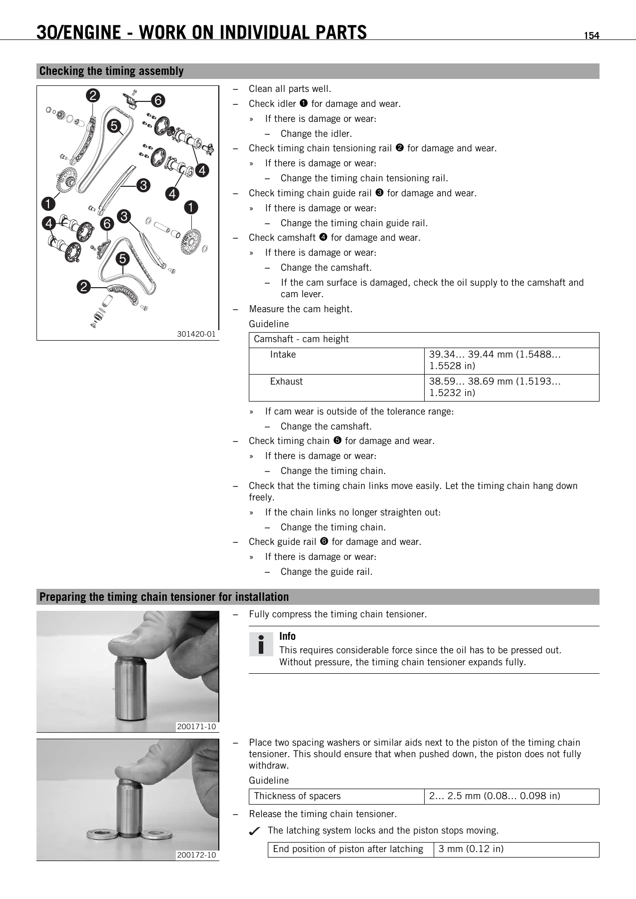
Checking the timing assemblyp. 156
Preparing the timing chain tensioner for installationp. 156
Checking the oil pressure regulator valvep. 157
Checking the oil pumpsp. 157
Checking the clutchp. 158
Checking the shift mechanismp. 159
Preassembling the shift shaftp. 160
Dismantling the main shaftp. 160
Dismantling the countershaftp. 161
Checking the transmissionp. 162
Assembling the main shaftp. 163
Assembling the countershaftp. 163
30/ASSEMBLING THE ENGINEp. 165
Installing the timing chain rails of the left engine case sectionp. 165
Installing the timing chain rails of the right engine case sectionp. 165
Installing the oil spray tubep. 166
Installing the transmission shaftp. 166
Installing the middle suction pumpp. 167
Installing the crankshaftp. 167
Installing the left engine casep. 168
Installing the locking leverp. 169
Installing the shift drum locatingp. 169
Installing the shift shaftp. 169
Installing the force pumpp. 170
Installing the left suction pumpp. 171
Setting the engine to ignition top dead center of the rear cylinderp. 171
Installing the primary gearp. 172
Installing the outer clutch hubp. 172
Installing the clutch facingp. 173
Installing the idler and timing chain on the rightp. 174
Installing the clutch coverp. 174
Installing the water pump wheelp. 175
Installing the gear position sensorp. 175
Installing the drive wheel of the balancer shaftp. 175
Installing the balancer shaftp. 176
Installing the idler and timing chain on the leftp. 176
Installing the oil filterp. 177
Installing the rotorp. 177
Installing the torque limiter and idlerp. 178
Installing the ignition pulse generatorp. 178
Installing the generator coverp. 178
Installing the oil drain plugp. 178
Installing the rear pistonp. 179
Installing the rear cylinder headp. 180
Installing the rear camshaftp. 181
Installing the rear timing chain tensionerp. 181
Setting the engine to ignition top dead center of the front cylinderp. 182
Installing the front pistonp. 182
Installing the front cylinder headp. 184
Installing the front camshaftsp. 184
Installing the front timing chain tensionerp. 185
Installing the heat exchangerp. 185
Installing the oil filler tubep. 186
Installing the starter motorp. 186
Checking the rear cylinder control timep. 186
Adjusting the rear cylinder control timep. 186
Checking the rear valve clearancep. 187
Adjusting the rear valve clearancep. 188
Checking the front cylinder control timep. 188
Adjusting the front cylinder control timep. 188
Checking the front valve clearancep. 189
Adjusting the front valve clearancep. 190
Installing the front valve coverp. 190
Installing the rear valve coverp. 190
Mounting the engine bracketp. 191
Dismounting the engine from the work standp. 191
31/SECONDARY AIR SYSTEMp. 192
Exhaust air injectionp. 192
32/CLUTCHp. 193
Checking fluid level of hydraulic clutchp. 193
Correcting fluid level of hydraulic clutchp. 193
34/SHIFT MECHANISMp. 194
Adjusting shift lever stubp. 194
Adjusting shift leverp. 194
35/WATER PUMP, COOLING SYSTEMp. 196
Checking the coolant levelp. 196
Checking the antifreezep. 196
Removing the radiatorp. 197
Installing the radiatorp. 197
Adding coolant/bleeding the cooling systemp. 198
Filling the cooling system compensating tankp. 199
36/CYLINDER HEADp. 200
Engine coolant temperature sensor cylinder 1p. 200
Engine coolant temperature sensor for cylinder 2p. 201
Checking the valve clearancep. 202
Adjusting the rear valve clearancep. 203
Adjusting the front valve clearancep. 204
Checking the rear cylinder control timep. 204
Checking the front cylinder control timep. 204
Adjusting the rear cylinder control timep. 205
Adjusting the front cylinder control timep. 206
Removing the rear camshaftp. 207
Installing the rear camshaftp. 207
Removing the front camshaftsp. 208
Installing the front camshaftsp. 208
Installing the rear timing chain tensionerp. 209
Installing the front timing chain tensionerp. 209
38/LUBRICATION SYSTEMp. 210
Oil circuitp. 210
Checking the engine oil levelp. 211
Changing the engine oil and filter, cleaning the oil screensp. 211
Draining engine oil, cleaning oil screensp. 211
Removing the oil filterp. 213
Installing the oil filterp. 214
Filling up with engine oilp. 214
Adding engine oilp. 215
Checking the engine oil pressurep. 215
Removing the oil jet for the clutch lubricationp. 217
Checking / cleaning the oil jet for clutch lubricationp. 218
Installing the oil jet for the clutch lubricationp. 218
39/IGNITION SYSTEMp. 220
Crankshaft position sensorp. 220
Ignition coilp. 220
41/THROTTLE VALVE BODYp. 221
Throttle position sensor circuit Ap. 221
Throttle position sensor circuit A – checking in the zero positionp. 221
Adjusting the position of the throttle position sensor in circuit Ap. 222
Removing the throttle valve body to adjustp. 223
Reinstalling the throttle valve body when the adjustments have been madep. 224
Throttle position sensor circuit Bp. 225
Manifold absolute pressure sensorp. 225
Connecting the vacuum hand pump to the manifold absolute pressure sensorp. 226
Ambient air pressure sensorp. 227
Injectorp. 227
Rollover sensorp. 228
EFI control unitp. 229
Requesting the EFI control unit activation codep. 229
Coding the EFI control unitp. 229
Flashing the EFI control unitp. 230
IMMOBILIZER BLINK CODEp. 231
ENGINE CONTROL TROUBLE CODEp. 240
CONNECTOR OVERVIEWp. 393
Motor drive circuit A connector AEp. 393
Connector AIp. 393
Crankshaft position sensor connector ALp. 393
Clutch switch, connector ALp. 393
Throttle position sensor circuit A, connector AMp. 393
Throttle position sensor circuit B, connector AMp. 394
Gear position sensor, connector AMp. 394
Fuel pump connector AMp. 394
Wheel speed sensor, connector AMp. 394
Connector AOp. 394
Diagnostic connection plug APp. 395
Rollover sensor connector APp. 395
Throttle position sensor circuit A, connector ARp. 395
Throttle position sensor circuit B, connector ARp. 396
Fuel pump connector ARp. 396
Side stand switch, connector ARp. 396
Ignition coil cylinder 1 connector ASp. 396
Ignition coil cylinder 2 connector ASp. 396
CAN bus terminating resistor connector ATp. 397
Crankshaft position sensor, connector ATp. 397
Clutch switch connector ATp. 397
Engine coolant temperature sensor cylinder 1 connector AXp. 397
Throttle stepper motor circuit B, connector CAp. 397
Lambda sensor cylinder 1, connector CAp. 398
Lambda sensor cylinder 2, connector CAp. 398
Lambda sensor cylinder 1, connector CEp. 398
Lambda sensor cylinder 2, connector CEp. 398
Secondary air valve connector CKp. 398
Connector CMp. 399
Connector COp. 399
Connector CPp. 400
Connector CQp. 400
Connector CUp. 400
Fuel evaporation valve connector DFp. 401
Secondary air valve connector DFp. 401
Electric starter lock control unit, connector DNp. 401
Immobilizer control unit, connector DNp. 401
Electric starter lock control unit, connector DOp. 401
Immobilizer control unit, connector DOp. 402
Ambient air pressure sensor connector DPp. 402
Manifold absolute pressure sensor cylinder 1, connector DPp. 402
Manifold absolute pressure sensor cylinder 2 connector DPp. 402
Injector cylinder 1 connector DQp. 402
Injector cylinder 2 connector DQp. 403
ICU antenna connector DVp. 403
Fuel pump relay connector EBp. 403
ICU antenna connector ELp. 403
Connector EQp. 403
Connector ERp. 404
Connector ESp. 404
Connector ETp. 404
Combination instrument connector EVp. 405
Exhaust air injection valve, connector FEp. 405
Fuel pump relayp. 406
CAN bus terminating resistorp. 406
TECHNICAL DATA – ENGINEp. 407
Capacity – engine oilp. 407
Capacity – coolantp. 408
TECHNICAL DATA – TOLERANCE, WEAR LIMITS OF ENGINEp. 409
TECHNICAL DATA – ENGINE TIGHTENING TORQUESp. 411
TECHNICAL DATA – CHASSISp. 413
Lighting equipmentp. 413
Capacity – fuelp. 414
TECHNICAL DATA – FORKp. 415
TECHNICAL DATA – SHOCK ABSORBERp. 416
TECHNICAL DATA – CHASSIS TIGHTENING TORQUESp. 417
CLEANING/CONSERVATIONp. 419
Cleaning motorcyclep. 419
Conservation for winter operationp. 419
STORAGEp. 421
Storagep. 421
Putting into operation after storagep. 421
SERVICE SCHEDULEp. 422
Important service tasks to be carried out by an authorized KTM-RC8 workshop.p. 422
Important service tasks to be carried out by an authorized KTM-RC8 workshop. (as additional job)p. 423
WIRING DIAGRAMp. 424
1 of 3p. 424
2 of 3p. 428
3 of 3p. 434
OPERATING SUBSTANCESp. 438
AUXILIARY SUBSTANCESp. 440
SPECIAL TOOLSp. 442
STANDARDSp. 454
INDEXp. 455
Ap. 455
Bp. 455
Cp. 455
Dp. 456
Ep. 456
Fp. 457
Hp. 457
Ip. 457
Kp. 457
Lp. 457
Mp. 457
Np. 457
Op. 457
Pp. 458
Rp. 458
Sp. 458
Tp. 458
Vp. 459
Wp. 459

Keihin EFI Fuel Injection, Ignition & Immobilizer Diagnostics

The electronic management section covers the Keihin fuel injection architecture, twin throttle valve bodies, manifold absolute pressure (MAP) sensors, ambient barometric sensors, and fuel pressure testing under operating loads (3.3 to 3.7 bar). Detailed diagnostics walk the user through throttle position sensor (TPS) circuit A and circuit B zero-position calibration using the KTM diagnostics tool. Exhaust emission monitoring covers the front and rear lambda sensors (HEGO1 and HEGO2 operating within 0.2 to 0.8 V closed-loop voltage) and internal ceramic heating element resistance (11.7 to 14.3 ohms at 20 degrees Celsius). Immobilizer control unit (ICU) programming is comprehensively instructed, detailing black ignition key activation, key deactivation, and ICU replacement pairing via the orange master programming key.

Cockpit Instrumentation, Firmware & Electrical Systems

Step-by-step documentation explains digital combination instrument operations, including BOOTLOADER mode activation, instrument software flashing (.kfw files), ROAD versus RACE display mode selection, shift light RPM1 and RPM2 configuration, lap timer blanking duration (LAP BLANK T), fuel reserve countdown calibration (TRIPF RESET), and service interval resets. The electrical section is anchored by full-system multi-page colored wiring diagrams, complete connector pin assignment directories, starter lock control unit testing, and fuse box protection schematics.

Document Table of Contents & Structure

Extracted directly from the publication’s official table of contents, the 2009 KTM 1190 RC8 R Repair Manual is organized into clearly indexed functional sections:

  • Means of Representation & Safety Information
  • Important Notes, Workshop Rules & Warranty Guidelines
  • Location of Serial Numbers (VIN, Engine, Fork, Shock, Steering Damper, Key Code)
  • Motorcycle Workstand Operations (Front, Middle Screw-In/Insertable, Rear Jacking & Starting Safety System)
  • 01 / Fork, Triple Clamp (Damping adjustments, spring preload, fork bleeding, height setup, complete fork servicing & DU bushing renewal)
  • 02 / Handlebar, Controls and Instruments (Clutch lever setup, steering damper tuning, handlebar height, throttle cable play, throttle grip cam replacement)
  • 03 / Frame (Side stand safety switch testing, multi-position footrest adjustments, rear subframe height positioning)
  • 04 / Shock Absorber, Swingarm (High/low-speed compression, rebound, preload, eccentric height adjuster, monoshock rebuild, nitrogen charging, vacuum bleeding, heim joints)
  • 05 / Exhaust (Lambda sensor voltage tests, sensor heater resistance, exhaust cover & silencer removal, manifold replacement)
  • 06 / Air Filter (Filter element replacement, airbox removal, lower airbox disassembly, intake air temperature sensor)
  • 07 / Fuel Tank, Seat, Trim (Bodywork dismounting, fuel tank removal, fuel pressure testing under load and actuator test)
  • 08 / Mask, Fender, Decal (Fairing side covers, inner covers, ECU bracket mounting)
  • 09 / Front Wheel (Front wheel removal/installation, spindle alignment, Brembo brake disc inspection, tire pressure specifications)
  • 10 / Rear Wheel (Rear wheel removal/installation, chain tensioning, chain wear measurement, sprocket & cush drive inspection)
  • 11 / Wiring Harness, Battery (Battery maintenance, charging procedures, starter lock control unit, fuel pump relay, fuse box assignments)
  • 13 / Brake System (Brembo radial caliper service, brake pad replacement, DOT 4/5.1 fluid bleeding, lever adjustment, pedal adjustment)
  • 14 / Light System, Instruments (Immobilizer ICU teaching, key coding, digital instrument BOOTLOADER mode, firmware updates, ROAD/RACE modes, shift warning RPM, headlight aiming)
  • 30 / Engine (Engine removal and installation, TDC locking bolt procedures, cylinder heads, camshafts, cylinders, pistons, generator cover, starter clutch, balancer shaft, oil pumps, slipper clutch, crankcase splitting, crankshaft, transmission cluster, bearing selection, reassembly & valve control timing)
  • 31 / Secondary Air System (SLS exhaust air injection valve testing & operation)
  • 32 / Hydraulic Clutch (Clutch fluid level inspection & hydraulic fluid top-up)
  • 34 / Shift Mechanism (Shift lever stub adjustment, shift rod length, reverse shift pattern options)
  • 35 / Water Pump, Cooling System (Coolant draining, radiator removal, 50 cm elevated bleeding procedure, thermostat switch)
  • 36 / Cylinder Head (Engine coolant temperature sensors, valve clearance inspection, shim calculations, camshaft control time adjustment)
  • 38 / Lubrication System (Triple oil pump diagnostics, pressure regulator valve testing, oil & filter change, clutch lubrication jet cleaning)
  • 39 / Ignition System (Crankshaft pulse generator air gap adjustment, stick ignition coils)
  • 41 / Throttle Valve Body (TPS circuit A/B zero-position adjustment, MAP sensors, injectors, rollover sensor, EFI control unit coding & flashing)
  • Immobilizer Blink Codes & Diagnostic Flash Sequences
  • Engine Control Trouble Codes (DTC fault tables & troubleshooting)
  • Harness Connector Overview & Pin Assignment Reference
  • Technical Data – Engine (Capacities, dimensions, oil circuit)
  • Technical Data – Tolerances and Wear Limits of Engine
  • Technical Data – Engine Tightening Torques & Threadlocker Specifications
  • Technical Data – Chassis, Lighting Equipment & Capacities
  • Technical Data – WP Front Fork Specifications
  • Technical Data – WP Rear Shock Absorber Specifications
  • Technical Data – Chassis Tightening Torques
  • Cleaning, Conservation & Winter Storage Instructions
  • Scheduled Maintenance Table & Periodic Service Tasks
  • Complete Electrical Wiring Diagrams (Part 1, Part 2, Part 3)
  • Operating Substances, Lubricants & Auxiliary Chemical Agents
  • Special Workshop Tools & Testing Equipment Directory
  • Standards & Alphabetic Subject Index

IMAGES PREVIEW

2009 KTM 1190 RC8 R Repair Manual — PDF page 1 preview
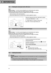
2009 KTM 1190 RC8 R Repair Manual — PDF page 21 preview
2009 KTM 1190 RC8 R Repair Manual — PDF page 156 preview

Together, these comprehensive chapters equip technicians with the precise data, sequence of operations, and diagnostic charts required to maintain the RC8 R at factory racing standard, eliminating guesswork across all mechanical and electrical operations.

Master-Level Workshop Standards & Factory Precision

Working on a high-output superbike demands exact adherence to factory tolerances and tightening specifications. The 2009 KTM 1190 RC8 R Repair Manual details critical technical parameters, such as the multi-angle cylinder head bolt torquing sequence (M11x1.5 bolts tightened in crisscross pattern: Step 1 at 15 Nm, Step 2 at 30 Nm, followed by two successive 90-degree angle rotations lubricated with engine oil). It outlines the primary drive gear locking specification (M33LHx1.5 left-hand thread at 130 Nm with Loctite 243), clutch center hub nut (M22x1.5 at 130 Nm with Loctite 243), and swingarm pivot spindle (M19x1.5 greased thread at 130 Nm). Specialized procedures such as raising the front wheel 50 cm during coolant filling to purge trapped air bubbles from the cylinder heads ensure long-term cooling system reliability under aggressive racetrack use.

Professional Capability, Technical Integrity, and Instant PDF Delivery

Investing in the authentic 2009 KTM 1190 RC8 R Repair Manual provides motorcycle owners, independent repair shops, and race mechanics with complete professional capability. Having access to genuine factory procedures, factory clearance limits, and dedicated KTM troubleshooting tables ensures that every repair, suspension modification, or engine rebuild is completed with absolute precision. Utilizing official torque values and threadlocking compounds preserves critical alloy threads, prevents expensive mechanical failures, and maintains the track-proven performance and safety engineered into the 1190 RC8 R platform. This manual is provided as an immediate digital PDF download upon checkout—eliminating shipping delays and physical book wear. The digital file is fully accessible across all devices including laptops, tablets, and mobile smartphones, and can be printed in full or by specific chapter for immediate use at the workbench or in the paddock.
Reviews

There are no reviews yet.

Be the first to review “2009 KTM 1190 RC8 R Repair Manual”

What Our Customers Say

★★★★★ Live reviews from customers
Loading customer reviews...
0
    0
    Your Cart
    Your cart is emptyReturn to Shop
    🛒
    Recently Purchased
    🕒 verified order