
2009 Volvo C30 S40 V50 C70 Wiring Diagram Manual TP39129202
Original price was: $32.95.$19.95Current price is: $19.95.
351-page 2009 Volvo wiring diagram publication TP 39129202 covering C30, S40 (04-), V50 and C70 (06-) electrical distribution, CAN/LIN/MOST networks, fuses, grounds, harness routing and system circuits.
Description
2009 Volvo C30 S40 V50 C70 Wiring Diagram Manual TP39129202
The 2009 Volvo C30 S40 V50 C70 Wiring Diagram Manual TP39129202 is the Volvo Car Corporation electrical wiring publication for the C30, S40 built from 2004 onward, V50, and C70 built from 2006 onward, compiled for the 2009 model year. Order number TP 39129202 replaces the earlier TP 39129201 issue and records vehicle changes introduced up to and including January 2008. It is an English-language circuit book: power distribution, fuse and relay maps, ground points, control-module networks, and system-by-system schematics rather than a mechanical workshop manual.
File Details
- Manual type: Wiring diagram
- Brand / models: Volvo C30, S40 (04-), V50, C70 (06-)
- Publication: TP 39129202 (replaces TP 39129201)
- Coverage date: 2009 wiring diagram; changes through January 2008
- Language: English
- Page count: 351
- File format: PDF
Which cars and engines appear in the diagrams
Body styles are split throughout so a technician can follow the correct branch. Separate sheets exist for C30 hatchback circuits, S40 sedan and V50 wagon circuits, and C70 convertible circuits, including the Convertible Roof Module (CRM), power roof, storage-compartment locking, and C70-specific door and side-panel harnesses. Left-hand drive and right-hand drive dashboard, floor, and door harness drawings are both present.
Engine-management wiring is drawn by powerplant, not as a single generic engine page. Gasoline coverage includes 4-cylinder 1.6 litre, 4-cylinder 1.8 litre and 2.0 litre, 5-cylinder, and 5-cylinder turbo circuits. Diesel coverage includes 4-cylinder 1.6 litre, 4-cylinder 2.0 litre, 4-cylinder 2.0 litre with MPS6, and 5-cylinder 2.4 litre. Matching emission-control, power-supply, starting, and climate pages follow the same engine families. Transmission pages cover automatic AW55-51, manual M66, automatic MPS6, and the Differential Electronic Module (DEM) used on S40/V50 all-wheel-drive layouts.
Volvo markets are abbreviated in the legend (EU/OS, USA, CDN, J, GB and others). The publication itself notes that models are sold in country-adapted versions and that some drawings or notes may not apply to every market. Anything introduced after January 2008 is outside this book and would have to be checked in later service bulletins.
How to read the 2009 Volvo C30 S40 V50 C70 Wiring Diagram Manual TP39129202
A dedicated how-to section explains component designations. Every device uses a type number plus a serial number (for example 3/x for a switch, 4/x for a control module, 6/x for a motor, 7/x for a sensor, 10/x for a lamp, 11/x for a fuse, 31/x for a ground, 63/x for a branching point, 64/x for a connector). The same codes reappear on the schematics, in the branching-point list, and in the seven-page component list at the back.
Symbol keys cover system voltage, chassis and component grounds, screened and twisted pairs, variant dashed lines, CAN-H and CAN-L, LIN, MOST, DIN/coaxial runs, distribution-box feed points, and the two connector styles (harness-to-harness versus connector on a component). Ignition-switch positions are defined as X (audio/accessories), S (key inserted), 15 (remains live during start), 15l (opens while cranking), 30 (battery constant), and 50 (start). Wire colours use the printed codes BK/SB, BN, BU/BL, GN, GY/GR, LGN, OG/OR, PK/P, RD/R, VT/VO, WH/W and YE/Y, including gold- and silver-plated contact notes where they appear on the sheets.
Power distribution, fuses, relays and grounds
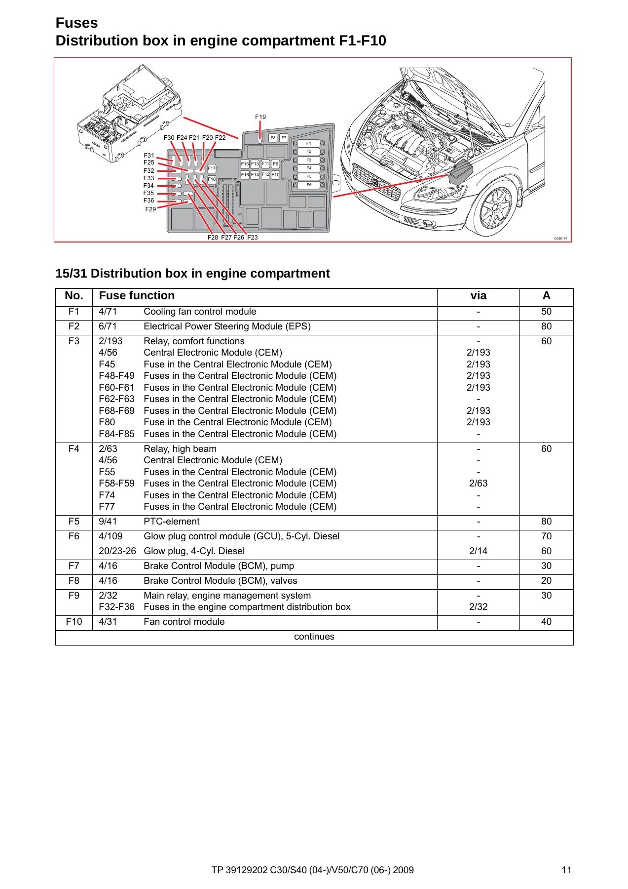
Electrical-distribution overviews show battery 1/1 feeding main fuses PF1 and PF2 (each listed at 150 A) into engine-compartment distribution box 15/31 and onward into Central Electronic Module 4/56. Engine-box fuse tables F1–F10, F11–F18, F20–F31, F32–F34 and F35–FH1 name the protected load, the intervening relay where used, and the ampere rating. Typical assignments include the cooling-fan control module, Electrical Power Steering Module, comfort-function relay feeds into the CEM, high-beam relay, PTC element, glow-plug control on 5-cylinder diesel, brake-control pump and valves, engine-management main relay, starter, trailer module, convertible-roof module, infotainment relay, wiper motor, horns, combustion preheater, subwoofer, TCM/ECM feeds, climate clutch, front fog lamps and auxiliary lights.
CEM fuse tables F43–F48, F49–F61, F62–F69, F73–F85 and F86 cover audio/USB/phone/multimedia, SRS, 12 V outlets, lighting switch and DIM, interior lamps, washer and rear-wiper relays, keyless module, data-link connector, gas-discharge lamp modules, seat heaters, sunroof, door modules, power seats, fuel-pump control and additive dosing, accessory module and tow-hitch 13-pin feed. Holder 11K carries the two 5 A Alcolock fuses. Relay maps locate horn, fog, fuel-filter preheater, headlamp washer, heated rear window, climate, glow-plug, starter and engine-management relays in box 15/31; fuel-pump and comfort relays plus the soldered interior-lamp, reversing-lamp, washer, high-beam, rear-wiper and infotainment relays inside the CEM; and accessory locations for auxiliary lights, handsfree, subwoofer and electric engine heater.
Ground pages start with a vehicle-plan overview and then list connection groups 31/3 through 31/119 with chassis locations such as MacPherson strut towers, A-posts, seat risers, engine points and trunk/tailgate grounds. Those lists are what you use when a circuit shows a 31/xx flag and you need the physical bolt rather than another schematic page.
Control modules and data networks
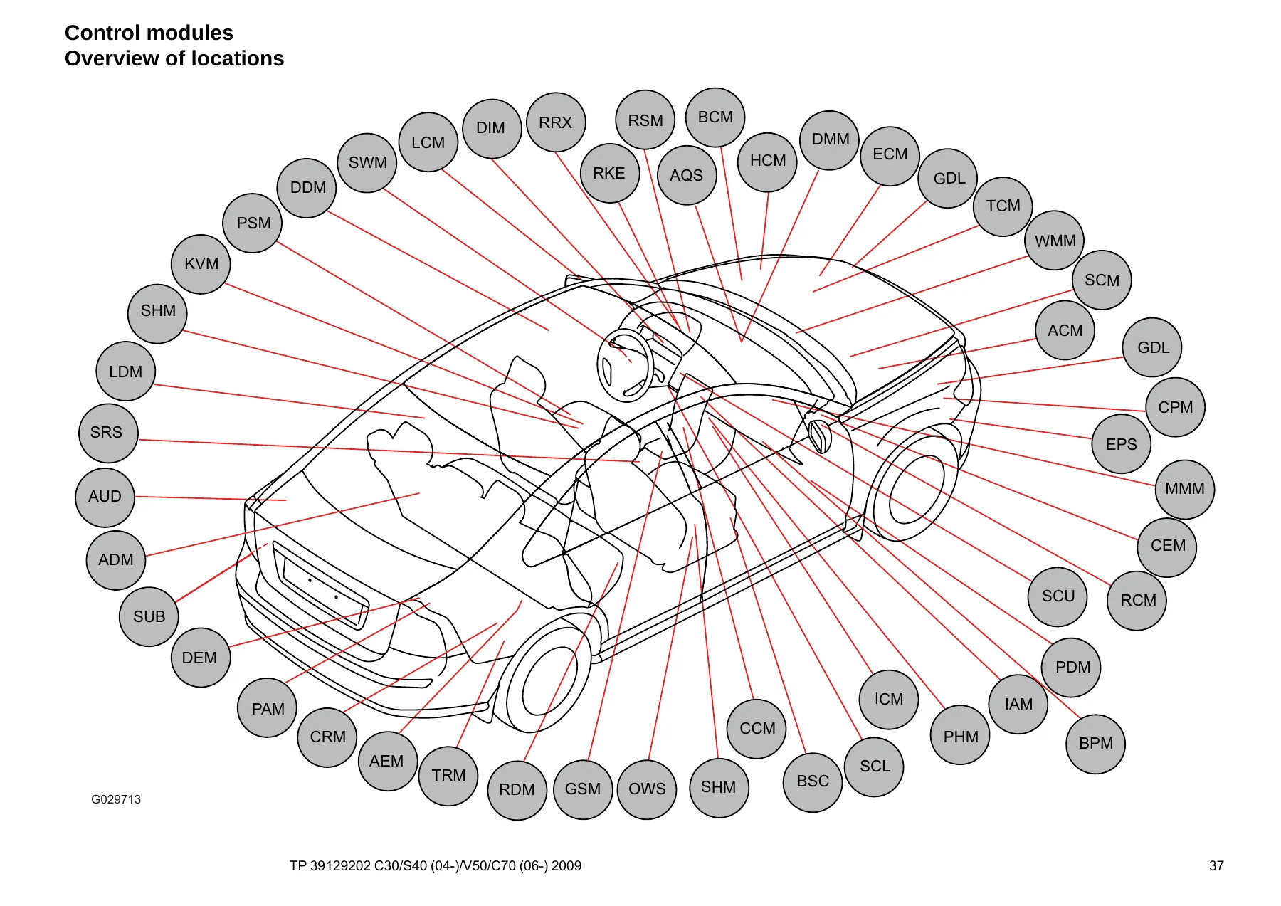
A location drawing and a designation table identify the modules that appear on the networks: CEM, ECM family 4/46.1–4/46.8, TCM, BCM, SRS, EPS, DEM, SCU, SCL, KVM, PAM, TRM, AEM, CRM, CCM, ICM, DIM, DDM/PDM/LDM/RDM, PSM, SHM, AUD, IAM, MMM, PHM, BPM, SUB, HCM, GDL master/slave, RSM, AQS, ADM, CPM, WMM, SCM, OWS, BSC, LCM and RCM among others.
Low-speed CAN, high-speed CAN, MOST and LIN are drawn as complete buses rather than as a single line on every system sheet. High-speed CAN ties ECM variants (including 5-cylinder 2.4 litre, 5-cylinder 2.5 litre turbo, 4-cylinder 1.6/1.8 litre gasoline and the 1.6/2.0 litre diesels plus MPS6) to BCM, CEM, EPS, HCM, TCM AW55-51 or MPS6, ADM, DEM, SWM and the diagnostic connector. MOST links IAM, ICM, AUD, PHM, MMM, BPM, RDAR and SUB. LIN ties CEM to SCU, SCL, GSM, RKE/RRX, WMM, RSM, GDL, seat heaters, climate dampers, door modules and selected ECM/ACM nodes. Start Control Module wiring shows PATS/immobilizer supply, key-in and inhibit, and the SCL LIN link. The Accessory Electronic Module pin table documents CAN, remote start, electric engine heater and alarm/handsfree pins.
System circuits in the 2009 Volvo C30 S40 V50 C70 Wiring Diagram Manual TP39129202
Group 23 fuel-system sheets give injector, sensor, pump and ECM pin-out paths for each engine family, with separate emission-control pages. Group 26 covers the cooling fan. Group 27 splits cruise control between 4-cylinder and 5-cylinder cars. Groups 32 and 33 cover alternator/voltage-regulator power supply and starting for 4- and 5-cylinder layouts.
Group 35 lighting is the largest exterior-lamp block: halogen high/low beam; Bi-Xenon active headlights on S40/V50 and Bi-Xenon high/low beam on C30/C70; running, parking and tail lamps with and without Bi-Xenon for each body; brake, reversing and fog lamps (including LHD Japan fog variants); follow-me-home lighting; interior lighting for C30/S40/V50 and for C70; instrument and control illumination; and auxiliary lamps. Group 36 continues with direction indicators and hazard flashers (halogen and Bi-Xenon), windshield and headlamp washers, C30/V50 rear wiper, rain sensor, keyless vehicle (separate C30/S40/V50 and C70 books), parking assistance, immobilizer and steering-column lock, horn, anti-theft alarm by body style, Alcolock and AEM accessory feeds.
Group 37 covers 12 V outlets, the diagnostics connector, 4-pin / 7-pin / 13-pin tow-hitch harnesses by body, and the USB control module. Group 38 is the driver information module and seat-belt reminder. Group 39 is the infotainment stack: base audio, high-performance/premium sound, cellular phone, multimedia and traffic information, satellite radio, subwoofer, portable navigation, Bluetooth, and the many handsfree combinations with internal or external amplifiers, AUU and AEM on LHD or RHD cars.
Further groups document transmission and DEM wiring; brake control with STC and with DSTC; electronic power steering; central locking, child safety lock, fuel-flap lock, power windows, sunroof and C70 power roof; power and heated mirrors, heated rear window and Blind Spot Information System; power seats with and without memory on LHD/RHD C30/C70 and S40/V50 plus heated seats; climate control for 4-cylinder gasoline, 1.6/2.0 diesel and 5-cylinder cars, PTC element, parking/auxiliary heater, electric engine heater and Flexifuel heater relay; and SRS for C30/S40/V50 and for C70 together with remote garage opening and the auto-dimming mirror.
After the schematics come connector drawings (from page 208), the branching-point index (from page 250), harness-routing drawings for engine, engine-compartment, dashboard, floor, roof, tunnel, door, rear side-panel and trunk/tailgate looms by model and drive side (from page 262), component illustrations (from page 287), the two-page index and the seven-page list of components.
IMAGES PREVIEW
Chapters Covered
- Vehicles with SRS (Airbag)/SIPS bag/IC — warnings and work notes
- Abbreviations — groups, ignition symbols, markets, colours
- How to use the wiring diagrams
- Electrical distribution overview
- Fuses — engine-compartment box F1–FH1, CEM F43–F86, battery PF1–PF2, holder 11K
- Relays — ignition switch, engine box R2–R14, CEM R15–R18 and soldered R1–R11B, accessory relays
- Ground connections — overview and 31/3–31/119 plus chassis grounds
- Control modules — locations, designations, CEM, low-speed CAN, high-speed CAN, MOST, LIN, SCU, AEM
- Group 23 Fuel system — engine management and emission control by gasoline and diesel family
- Group 26 Cooling system — cooling fan
- Group 27 Engine controls — cruise control 4-cyl. and 5-cyl.
- Group 32 Alternator and voltage regulator — power supply 4-cyl. and 5-cyl.
- Group 33 Starting system — 4-cyl. and 5-cyl.
- Group 35 Lighting — beams, Bi-Xenon, lamps, interior and auxiliary lighting
- Group 36 Additional electrical equipment — indicators, wipers, keyless, alarm, parking aid, immobilizer
- Group 37 Wiring and fuses — outlets, diagnostics, tow hitch, USB
- Group 38 Instruments — DIM and seat-belt reminder
- Group 39 Other — audio, phone, multimedia, Bluetooth, navigation, satellite radio
- Group 43 Transmission — AW55-51, M66, MPS6, DEM
- Group 59 Brake system — BCM with STC and DSTC
- Group 64 Steering — electronic power steering
- Group 83 Doors and openings — locking, windows, sunroof/power roof
- Group 84 Exterior decorative elements — mirrors, heated glass, BLIS
- Group 85 Interior equipment — power and heated seats
- Group 87 Climate control system — ECC, PTC, heaters
- Group 88 Internal equipment — SRS, garage opener, auto-dimming mirror
- Connectors
- Branching points
- Routing of harnesses in the car
- Component illustrations
- Index and list of components
Taken together, the book lets a technician trace a circuit from battery or CEM fuse through the correct relay and network node to the lamp, motor, sensor or module, then find the connector, splice and ground on the car. It does not replace mechanical repair procedures; it is the electrical map those procedures assume you already have.
Using the diagrams on the car
Open the relevant system sheet, note wire colour and destination codes, then jump to the connector or branching-point chapter when a 64/xx or 63/xx number appears. Confirm the physical module with the location overview and the illustrated parts pages. Fuse ampere values printed next to F-numbers are the ratings used in the 2009 distribution boxes, which is the information needed when a circuit is dead and you are deciding whether the fuse, the relay coil feed, or the downstream load is at fault. SRS, SIPS and inflatable-curtain pages carry explicit warnings that work affecting those systems must follow the methods in the SRS service information; the wiring book shows the circuits, not the disable/enable procedure itself.
Get the wiring diagrams and start tracing circuits
With the 2009 Volvo C30 S40 V50 C70 Wiring Diagram Manual TP39129202 you can diagnose lighting, starting, charging, engine-management, climate, locking, roof, audio and network faults on the C30, S40 (04-), V50 and C70 (06-) using the same fuse lists, ground map and CAN/LIN/MOST drawings a shop uses for those cars. Correct wire colours, pin numbers and module codes prevent swapped grounds, back-probed connectors and guesswork on Bi-Xenon, keyless and convertible-roof circuits. The file is delivered as an instant PDF after payment — no shipping, readable on any device, and printable when you need a sheet on the fender.
Reviews
There are no reviews yet.