
2011 Volvo V70 XC70 S80 Complete Wiring Diagram Manual TP 39180202 PDF
Original price was: $29.95.$17.95Current price is: $17.95.
Complete factory-format electrical wiring diagram manual (TP 39180202) covering the 2011 Volvo V70 (08-), XC70 (08-) and S80 (07-) — every circuit, fuse, relay, connector and ground point in full color diagrams.
Description
2011 Volvo V70, XC70 & S80 Wiring Diagram Manual (TP 39180202)
This is the complete 2011 Volvo V70 XC70 S80 wiring diagram manual, document number TP 39180202, covering the V70 (2008-), XC70 (2008-) and S80 (2007-) model range. Every circuit in the vehicle is mapped in full-color schematic form, making this the reference document for anyone tracing an electrical fault, retrofitting an accessory, or simply trying to understand how a specific Volvo system is wired.
- Manual type: Wiring Diagram (Electronic Wiring Diagram format)
- Brand/Model: Volvo V70 (08-), XC70 (08-), S80 (07-)
- Language: English
- Page count: 380 pages
- File format: PDF (instant digital download)
- Document number: TP 39180202
- Edition/Date: Changes introduced up to May 2010
IMAGES PREVIEW
Chapters Covered
- Vehicles with SRS (Airbag)/SIPS bag/IC (Inflatable curtain)
- Explanations & Abbreviations
- How to use the wiring diagrams
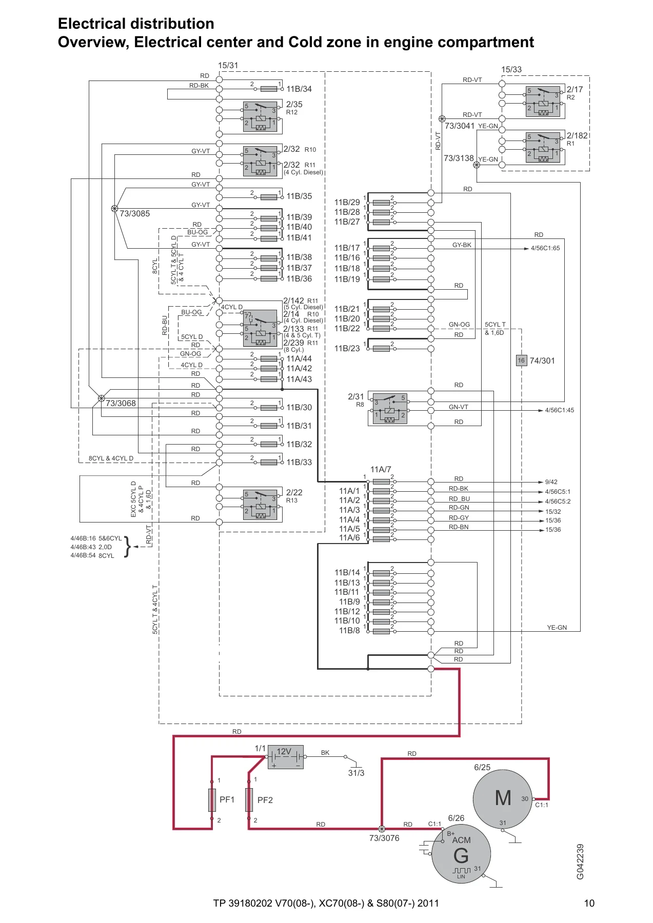
- Electrical distribution — electrical center, cold zone, distribution boxes in engine compartment, cargo compartment and passenger compartment
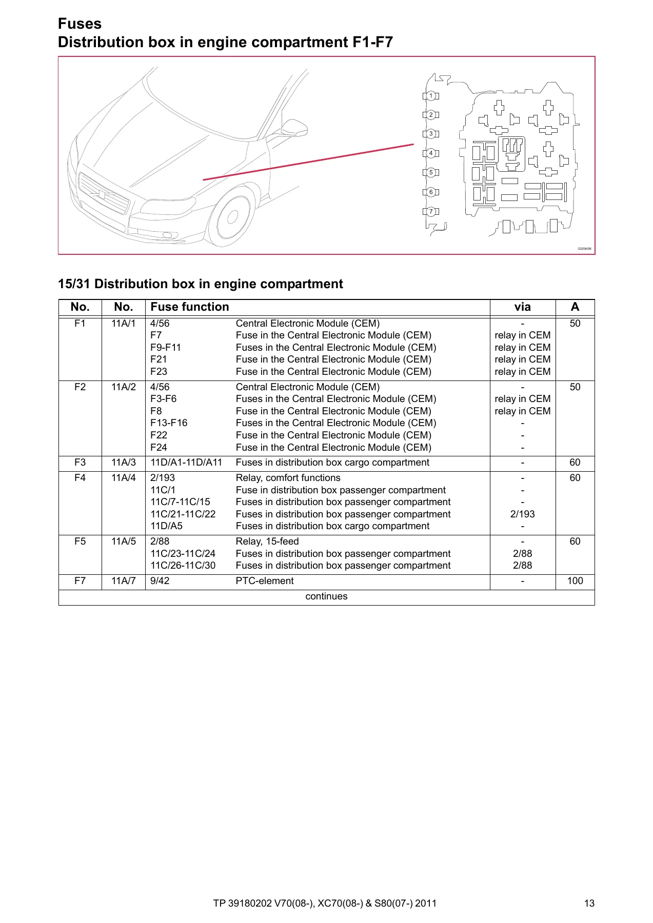
- Fuses — every distribution box and Central Electronic Module (CEM) fuse group
- Relays — engine compartment, passenger compartment, cargo compartment, CEM
- Ground connections — full 31/1 through 31/AL ground point listing
- Control modules — overview, designations, Central Electronic Module (CEM), data communication high/intermediate speed CAN, LIN, MOST, Steering Wheel Module (SWM)
- Group 23 Fuel system — engine management for 4-, 5-, 6- and 8-cylinder, turbo and diesel variants, emission control
- Group 26 Cooling system — cooling fan circuits, 4-, 5-, 6- and 8-cylinder, diesel and turbo
- Group 27 Engine controls — cruise control, all engine variants
- Group 32 Alternator and voltage regulator — power supply circuits
- Group 33 Starting system — 4-, 5-, 6- and 8-cylinder, diesel variants
- Group 35 Lighting — high/low beam, Dual Xenon, running/parking/tail/brake/fog/reversing lights, interior lighting, active headlight
- Group 36 Additional electrical equipment — rain sensor, indicators/hazard, wiper/washer, keyless vehicle, horn, anti-theft alarm, parking assistance, TPMS, alcolock
- Group 37 Wiring and fuses — diagnostics system, 12V outlet, towbar/tow hitch cable harnesses, AUU
- Group 38 Instruments — seat belt reminder, driver information module, analog clock
- Group 39 Other — cellular phone, audio, DAB radio, Bluetooth, multimedia, rear seat entertainment, satellite radio, parking camera, navigation
- Group 43 Transmission — M66, TF-80SC AWD automatic, MPS6 automatic, Differential Electronic Module (DEM)
- Group 55 Parking brake — electric parking brake
- Group 59 Brake system — brake control system & DSTC
- Group 64 Steering — speed dependent power steering
- Group 76 Shock absorbers — Four-C system
- Group 83 Doors and openings — central locking, power windows, power sunroof
- Group 84 Exterior decorative elements — power/heated door mirrors, blind spot information system, heated rear window
- Group 85 Interior equipment — memory seats, heated seats, massage seats
- Group 87 Climate control system — PTC-elements, 4-, 5-, 6- and 8-cylinder, diesel, parking heater, auxiliary heater
- Group 88 Internal equipment — auto-dimming mirror, supplemental restraint system
- Connectors, Branching points, Cable harness routing in vehicle
- Component illustrations, Index, List of components
Taken together, this document gives a technician a complete electrical map of the vehicle — from the Central Electronic Module (CEM) down to individual connector pins — with color-coded wire tracing, component designations, and cross-references to every fuse, relay and ground point in the car.
Why Technicians Rely on the 2011 Volvo V70 XC70 S80 Wiring Diagram Manual
This 2011 Volvo V70 XC70 S80 wiring diagram manual (TP 39180202) enables accurate diagnosis of no-start conditions, short circuits, blown fuses, module communication faults on CAN/LIN/MOST networks, and lighting or accessory wiring issues across the V70, XC70 and S80 lineup. Because the diagrams follow Volvo’s own component designation and branching-point system, faults can be traced circuit by circuit rather than guessed at, and correct wire colors, connector pinouts and fuse ratings can be confirmed before any repair is attempted.
Whether you’re chasing an intermittent short in the cargo compartment distribution box, wiring in an accessory USB unit, or verifying ground connections after bodywork, this wiring diagram manual gives you the exact routing and specification Volvo engineers documented for the V70, XC70 and S80. The file downloads instantly as a PDF after purchase — no shipping, no waiting — and can be viewed on a laptop, tablet or phone in the shop, or printed one section at a time for bench reference.
Reviews
There are no reviews yet.