Description
File Details
- Manual type: Wiring diagram
- Brand / models: Volvo V70 (08-), XC70 (08-) and S80 (07-)
- Publication: Wiring Diagram 2014, TP 39264202
- Coverage cutoff: Changes introduced up to and including structure week 13w20
- Language: English
- Page count: 372
- File format: PDF
- Copyright line: Volvo Car Corporation 2013
The 2014 Volvo V70 XC70 S80 Wiring Diagram TP39264202 Electrical Schematic Manual is the electrical map for three related Volvo platforms sold in left-hand drive and right-hand drive form. Circuits are drawn in the non-active state (key removed, doors, hatches and hood closed) so a technician can follow power, ground and data paths without guessing which contacts should be live.
Vehicles and Variants in This Publication
Cover artwork and running headers identify V70 (08-), XC70 (08-) and S80 (07-). Separate sheets exist wherever body style or steering position changes the harness: tail lamps, brake lamps and reversing lamps are split V70 versus S80; interior lighting, follow-me-home lighting, direction indicators and power windows are split LHD versus RHD; floor, dashboard and infotainment harness drawings are likewise split by model and drive side. Tow-hitch harnesses appear in 4-pin, 7-pin and 13-pin versions for both V70 and S80.
The book also flags market adaptations. Abbreviations list countries and regions (USA, CDN, EU/OS, GB, WEU and others) because Volvo sold legally different lighting and equipment packages. Illustrations that do not apply to every market are still printed; the technician matches the sheet to the car on the hoist rather than assuming every option is fitted.
Powertrains Shown on the Schematics
Engine management, starting, charging, cooling-fan and emission sheets are broken out by cylinder count and fuel:
- 4-cylinder 1.6l Turbo and 4-cylinder 2.0l Turbo
- 4-cylinder Diesel, including Start/Stop 1.6l Diesel DV6C
- 5-cylinder Turbo and 5-cylinder Diesel, with and without Start/Stop
- 6-cylinder, 6-cylinder Turbo and 6-cylinder PZEV
Related power-supply pages cover 4-cylinder Turbo charging, 4- and 5-cylinder cars with Start/Stop (secondary battery 1/2, battery relay 2/166, BMS 7/240) and 5- and 6-cylinder charging without that system. Transmission circuits include manual M66, automatic MPS6 and automatic AWF21, plus the Differential Electronic Module on all-wheel-drive cars. Glow-plug control, fuel-flow valves, EVAP solenoids, variable valve timing solenoids, MAF sensors and heated oxygen sensors appear on the fuse and engine-management pages that match each engine family.
How the Diagrams Are Read
A dedicated “How to use the wiring diagrams” section explains the two-part component code used everywhere in the 2014 Volvo V70 XC70 S80 Wiring Diagram TP39264202 Electrical Schematic Manual. Type number plus serial number produces designations such as 3/2 for a switch or 4/56 for the Central Electronic Module. Type groups printed in the book include battery (1), relay (2), switch (3), control module (4), driver information module (5), electric motor (6), sensor (7), actuator (8), heating element (9), lamp (10), fuse (11), distribution box (15), audio (16), diagnostics (17), contact reel (18), meter (19), ignition component (20), optics (27), ground (31), branching point (73) and connector (74).
The symbol key shows system voltage (drawn in red on the sample sheet), chassis grounds, screened and twisted pairs, CAN H / CAN L, LIN, MOST, DIN/coaxial data, distribution-box taps, inter-harness connectors and in-component connectors. Wire colors use the printed codes BK/SB, BN, BU/BL, GN, GY/GR, LGN, NL, OG/OR, PK/P, RD/R, VT/VO, WH/W and YE/Y. Ignition-switch positions are marked X, S, 15, 15l, 30 and 50. Numbered branching points such as 73/5035 are indexed later so every device hanging on a splice can be listed in one place.
Electrical Distribution, Fuses and Relays
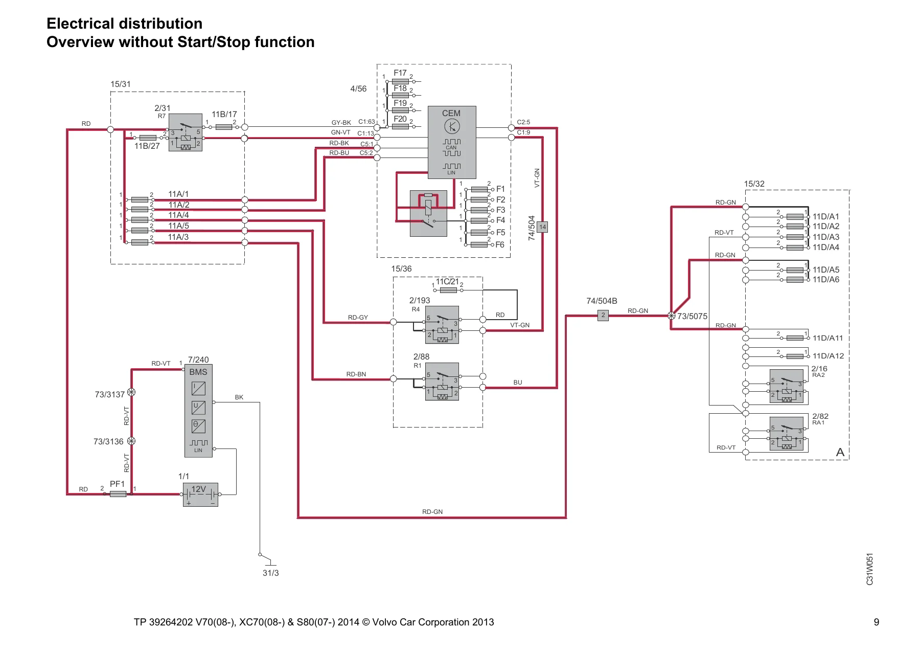
Overview sheets map power from the battery through the engine-compartment box 15/31, passenger-compartment box 15/36, cargo box 15/32 and, on Start/Stop cars, the cold-zone box 15/37. Fuse tables then name every circuit:
- Engine box F1–F44, including 50 A CEM feeds, 60 A cargo and comfort feeds, 100 A PTC element, heated windshield, wiper motor, BCM pump and valves, cooling-fan modules (60 A or 80 A by engine) and 100 A electric power steering
- CEM internal fuses F1–F24 for rear wiper, courtesy lamps, DIM, rain sensor, washers, fuel pump, SRS, ICM/IAM audio, sunroof and ignition switch
- Passenger box F1–F30 for door modules DDM/PDM/LDM/RDM, keyless module, power seats, infotainment, climate damper motors, seat heaters, parking assistance, DEM and Four-C suspension
- Cargo box FA1–FA11 for park-brake module, heated rear window, tow-hitch 13-pin outlet, power tailgate and trailer module
- Battery main fuses PF1–PF2 and cold-zone F1–MF2
Relay pages locate horn, starter, glow-plug, climate clutch, 15-feed, comfort, headlight-washer, heated-rear-window and auxiliary-light relays in the three distribution boxes. Ground overviews then walk 31/2 through 31/AL so a no-ground complaint can be traced to a specific wheel-house, bottom-rail, bumper abutment or roof point instead of a generic “body earth.”
Chapters Covered
- Explanations and abbreviations; how to use the wiring diagrams (component codes, symbols, branching points, connectors)
- Electrical distribution — overviews without and with Start/Stop; engine, passenger and cargo distribution boxes
- Fuses — engine F1–F44, CEM F1–F24, passenger extra holder, passenger F1–F30, cargo FA1–FA11, cold zone, battery PF1–PF2
- Relays — engine, passenger and cargo compartments
- Ground connections — overview and point-by-point sheets 31/2–31/AL
- Control modules — locations, designations, CEM 1:3, high-speed CAN, high-speed CAN 4-cyl., intermediate-speed CAN LHD/RHD, MOST, LIN, Steering Wheel Module
- Group 26 Cooling system — cooling fan 4-cyl. Turbo, 5-cyl. Turbo, 6-cyl., 4-cyl. Diesel, 5-cyl. Diesel
- Group 27 Engine controls — cruise control by engine; Start/Stop 4-cyl. 1.6l Turbo, 4-cyl. 1.6l Diesel, 5-cyl. Diesel, 5-cyl. Turbo
- Group 28 Ignition and control — engine management 4-cyl. Diesel, 4-cyl. Turbo 1.6l and 2.0l, 5-cyl. Turbo, 5-cyl. Diesel, 6-cyl. PZEV, 6-cyl., 6-cyl. Turbo; emission control sheets by engine
- Group 32 Alternator and voltage regulator — power supply 4-cyl. Turbo, 4- and 5-cyl. with Start/Stop, 5- and 6-cyl.
- Group 33 Starting system — 4-cyl. Turbo, 5- and 6-cyl., 4-cyl. Diesel, 5-cyl. Diesel
- Group 35 Lighting — high/low beam and Dual Xenon, manual beam-length, running/parking and tail lamps V70/S80, DRL, brake and reversing lamps, follow-me-home LHD/RHD, interior lighting, active headlight, sill, auxiliary, mug-holder and floor lamps
- Group 36 Additional electrical equipment — rain sensor, indicators and hazards LHD/RHD V70/S80, washers, keyless vehicle, horn, alarm, parking assistance, collision warning, TPMS, alcohol lock
- Group 37 Wiring and fuses — diagnostics, 12 V outlets, tow-hitch 4/7/13-pin V70 and S80, Accessory USB unit
- Group 38 Instruments — seat-belt reminder, Driver Information Module, analog clock
- Group 39 Other / accessories — TV, cellular phone, audio and Audio Premium, DAB, Bluetooth, rear-seat entertainment V70, satellite radio, parking cameras, portable navigation, Sensus Connected Touch
- Group 43 Transmission — M66, MPS6, AWF21, DEM
- Group 55 Electric parking brake; Group 59 brake control and DSTC; Group 64 speed-dependent power steering; Group 76 Four-C dampers
- Group 83 Doors — central locking front/rear/tailgate/fuel flap, power windows, sunroof
- Group 84 Exterior — power and heated mirrors, BLIS, heated windshield LHD/RHD, heated rear window
- Group 85 Interior — power seats with memory, heated steering wheel, heated front/rear seats, massage seats
- Group 87 Climate — 4-cyl. Turbo, 4-cyl. Diesel, 5- and 6-cyl., PTC elements, parking/auxiliary heater, remote start, rear refrigeration box
- Group 88 Internal equipment — SRS 1:2, folding headrests, garage opener, auto-dimming mirror
- Connectors (from page 221) and branching points (from page 261)
- Cable harness routing — engine harnesses by 4-/5-/6-cyl. and diesel, engine-compartment, dashboard, floor, infotainment, roof, console, tunnel, doors, tailgate, rear axle and executive harnesses
- Component illustrations, index and list of components 1:7 through 7:7
Complete PDF Bookmark Tree
Complete Bookmarks
The complete bookmarks in the “2014 Volvo V70 XC70 S80 Wiring Diagram TP39264202 Electrical Schematic Manual” are as follows:
VOLVO V70 (08-), XC70 (08-) & S80 (07-)p. 1
TP 39264202 Structure week 13w20p. 1
Vehicles with SRS (Airbag)/SIPS bag/IC (Inflatable curtain)p. 2
+Table of Contents 1:3p. 3
Table of Contents 2:3p. 4
Table of Contents 3:3p. 5
+Explanationsp. 6
+How to use the wiring diagrams 1:2p. 7
How to use the wiring diagrams 2:2p. 8
+Electrical distributionp. 9
Overview without Start/Stop functionp. 9
Overview with Start/Stop functionp. 10
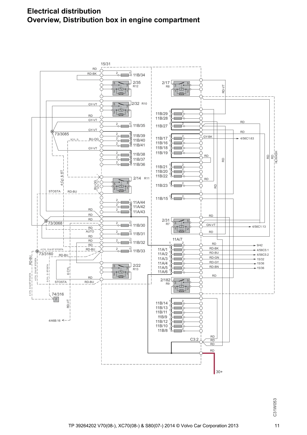
Overview, Distribution box in engine compartmentp. 11
Overview, Distribution box in passenger compartmentp. 12
Overview, Distribution box in cargo compartmentp. 13
+Fusesp. 14
Distribution box in engine compartment F1-F7p. 14
Distribution box in engine compartment F8-F21p. 15
Distribution box in engine compartment F22-F31p. 16
Distribution box in engine compartment F32-F37p. 17
Distribution box in engine compartment F38p. 18
Distribution box in engine compartment F38-F39p. 19
Distribution box in engine compartment F39-F44p. 20
Central electronic module (CEM) F1-F3p. 21
Central electronic module (CEM) F4-F14p. 22
Central electronic module (CEM) F15-F24p. 23
Passenger compartmentp. 24
Distribution box in passenger compartment F1-F17p. 25
Distribution box in passenger compartment F18-F24p. 26
Distribution box in passenger compartment F25-F30p. 27
Distribution box in cargo compartment FA1-FA11p. 28
Distribution box in engine compartment, cold zone F1-MF2p. 29
Battery PF1-PF2p. 30
+Relaysp. 31
Relays in the engine compartmentp. 31
Relays in the engine compartmentp. 32
Relays in passenger compartmentp. 33
Relays in cargo compartmentp. 34
+Ground connectionsp. 35
Overviewp. 35
31/2 – 31/6p. 36
31/7 – 31/10p. 37
31/10 – 31/15p. 38
31/47 – 31/65p. 39
31/66 – 31/83p. 40
31/84 – 31/90p. 41
31/93 – 31/XX4p. 42
31/XX10 – 31/ALp. 43
+Control modulesp. 44
Overview locationsp. 44
Overview designationsp. 45
+Central Electronic Module (CEM) 1:3p. 46
Central Electronic Module (CEM) 2:3p. 47
Central Electronic Module (CEM) 3:3p. 48
Data communication high speed CANp. 49
Data communication high speed CAN, 4-Cyl.p. 50
Data communication intermediate speed CAN, LHDp. 51
Data communication intermediate speed CAN, RHDp. 52
Data communication MOSTp. 53
+Data communication, LIN 1:2p. 54
Data communication, LIN 2:2p. 55
Steering Wheel Module (SWM)p. 56
+Group 26 Cooling systemp. 57
Cooling fan, 4-Cyl. Turbop. 57
Cooling fan, 5-Cyl. Turbop. 58
Cooling fan, 6-Cyl.p. 59
Cooling fan, 4-Cyl. Dieselp. 60
Cooling fan, 5-Cyl. Dieselp. 61
+Group 27 Engine controlsp. 62
Cruise control 4-Cyl. 1,6l Turbop. 62
Cruise control 4-Cyl. 2,0l Turbop. 63
Cruise control 4-Cyl. Dieselp. 64
Cruise control 5-Cyl. & 6-Cyl.p. 65
Cruise control 5-Cyl. Dieselp. 66
Start-/Stop function 4-Cyl. 1.6l Turbop. 67
Start-/Stop function 4-Cyl. 1.6l Dieselp. 68
Start-/Stop function 5-Cyl. Dieselp. 69
Start-/Stop function 5-Cyl. Turbop. 70
+Group 28 Ignition and control systemp. 71
+Engine management system, 4-Cyl. Diesel 1:3p. 71
Engine management system, 4-Cyl. Diesel 2:3p. 72
Engine management system, 4-Cyl. Diesel 3:3p. 73
+Engine management system, 4-Cyl. Turbo 1.6l 1:2p. 74
Engine management system, 4-Cyl. Turbo 1.6l 2:2p. 75
+Engine management system, 4-Cyl. Turbo 2.0l 1:2p. 76
Engine management system, 4-Cyl. Turbo 2.0l 2:2p. 77
+Engine management system, 5-Cyl. Turbo 1:2p. 78
Engine management system, 5-Cyl. Turbo 2:2p. 79
+Engine management system, 5-Cyl. Diesel 1:3p. 80
Engine management system, 5-Cyl. Diesel 2:3p. 81
Engine management system, 5-Cyl. Diesel 3:3p. 82
+Engine management system 6-Cyl. PZEV 1:2p. 83
Engine management system 6-Cyl. PZEV 2:2p. 84
+Engine management system, 6-Cyl. 1:2p. 85
Engine management system, 6-Cyl. 2:2p. 86
+Engine management system, 6-Cyl. Turbo 1:2p. 87
Engine management system, 6-Cyl. Turbo 2:2p. 88
Emission control 4-Cyl. 1.6l Turbop. 89
Emission control 4-Cyl. 2.0l Turbop. 90
Emission control 5-Cyl. Turbop. 91
Emission control 6-Cyl.p. 92
Emission control 6-Cyl. Turbop. 93
+Group 32 Alternator and voltage regulatorp. 94
Power supply 4-Cyl. Turbop. 94
Power supply 4-Cyl. & 5-Cyl. with start/stopp. 95
Power supply 5-Cyl. & 6-Cyl.p. 96
+Group 33 Starting systemp. 97
Starting system 4-Cyl. Turbop. 97
Starting system 5- & 6-Cyl.p. 98
Starting system 4-Cyl. Dieselp. 99
Starting system 5-Cyl. Dieselp. 100
+Group 35 Lightingp. 101
High and low beamp. 101
High and low beam (Dual Xenon)p. 102
Beam length adjustment, manualp. 103
Running/Parking light, Tail lights V70p. 104
Running/Parking light, Tail lights S80p. 105
Daytime running lights V70 & XC70p. 106
Daytime running lights S80p. 107
Brake lights V70p. 108
Brake lights S80p. 109
Reversing lights V70p. 110
Reversing lights S80p. 111
Follow-me-home lighting LHDp. 112
Follow-me-home lighting RHDp. 113
+Interior lighting, LHD 1:2p. 114
Interior lighting, LHD 2:2p. 115
+Interior lighting, RHD 1:2p. 116
Interior lighting, RHD 2:2p. 117
Active headlightp. 118
Lighting in door sill trimsp. 119
Auxiliary lightsp. 120
Lighting mug holder and floorp. 121
+Group 36 Additional electrical equipmentp. 122
Rain sensorp. 122
Direction indicator and hazard warning flashers LHD V70p. 123
Direction indicator and hazard warning flashers LHD S80p. 124
Direction indicator and hazard warning flashers RHD V70p. 125
Direction indicator and hazard warning flashers RHD S80p. 126
Wiper/washer windshieldp. 127
High pressure headlight washerp. 128
Wiper/Washer rear windowp. 129
+Keyless vehicle 1:2p. 130
Keyless vehicle 2:2p. 131
Hornp. 132
Anti-theft alarmp. 133
Parking assistancep. 134
Collision warning with power brake boosterp. 135
Tire pressure monitoring system (TPMS)p. 136
Alcohol lockp. 137
+Group 37 Wiring and fusesp. 138
Diagnostics systemp. 138
Outlet 12 Vp. 139
Outlet 12 V, S80p. 140
Cable harness towbar/tow hitch 4-pin V70p. 141
Cable harness towbar/tow hitch 4-pin S80p. 142
Cable harness towbar/tow hitch 7-pin V70p. 143
Cable harness towbar/tow hitch 7-pin S80p. 144
Cable harness towbar/tow hitch 13-pin V70p. 145
Cable harness towbar/tow hitch 13-pin S80p. 146
Accessory USB unit (AUU)p. 147
+Group 38 Instrumentsp. 148
Seat belt reminderp. 148
Driver information modulep. 149
Analog clockp. 150
+Group 39 Other, Accessoriesp. 151
TVp. 151
+Cellular phone 1:2p. 152
+Audio 1:2p. 154
+Audio Premium 1:3p. 156
Audio Premium 2:3p. 157
Audio Premium 3:3p. 158
DAB Radiop. 159
Bluetooth Handsfreep. 160
Rear seat entertainment, V70p. 161
Satellite radiop. 163
Parking camerap. 164
Parking camera wide-angle, frontp. 165
Navigation system, portablep. 166
Sensus Connected Touchp. 167
+Group 43 Transmissionp. 168
Transmission M66p. 168
Automatic transmission MPS6p. 169
Automatic transmission AWF21p. 170
Differential Electronic Module (DEM)p. 171
+Group 55 Parking brakep. 172
Electric parking brakep. 172
+Group 59 Brake systemp. 173
Brake control system & DSTCp. 173
+Group 64 Steeringp. 174
Speed dependent power steeringp. 174
+Group 76 Shock absorbersp. 175
+Group 83 Doors and openingsp. 176
Central locking front doors LHDp. 176
Central locking front doors RHDp. 177
Central locking rear doorsp. 178
Central locking trunk lid/tailgate V70p. 179
Central locking trunk lid/tailgate S80p. 180
Central locking fuel filler flapp. 181
Signal receiver central lockingp. 182
Power windows front doors LHDp. 183
Power windows front doors RHDp. 184
Power windows rear doorsp. 185
Power sunroofp. 186
+Group 84 Exterior decorative elements, etc.p. 187
Power door mirrors LHDp. 187
Power door mirrors RHDp. 188
Heated door mirrors LHDp. 189
Heated door mirrors RHDp. 190
Blind spot information system LHDp. 191
Blind spot information system RHDp. 192
Heated windshield LHDp. 193
Heated windshield RHDp. 194
Heated rear windowp. 195
+Group 85 Interior equipmentp. 196
Power driver’s seat with memory function, LHDp. 196
Power driver’s seat with memory function, RHDp. 197
Power passenger seat, LHDp. 198
Power passenger seat, RHDp. 199
Heated steering wheelp. 200
Heated front seats with fansp. 201
Heated front seats without fansp. 202
Heated rear seatp. 203
Massage seats 1:2p. 204
Massage seats 2:2p. 205
+Group 87 Climate control systemp. 206
+Climate control system, 4-Cyl. Turbo 1:2p. 206
Climate control system, 4-Cyl. Turbo 2:2p. 207
+Climate control system 4-Cyl. Diesel 1:2p. 208
Climate control system 4-Cyl. Diesel 2:2p. 209
Climate control system 5- & 6-Cyl. 1:2p. 210
Climate control system PTC-elementsp. 212
Parking heater, auxiliary heaterp. 213
Parking heater, remote startp. 214
Refrigeration box rear seatp. 215
+Group 88 Internal equipmentp. 216
+Supplemental restraint system 1:2p. 216
Supplemental restraint system 2:2p. 217
Power folding headrestp. 218
Remote control garage openingp. 219
Rear-view mirror with automatic dimmingp. 220
+Connectorsp. 221
74/9 – 74/30:1-7p. 221
74/30:8-20p. 222
74/31:1-15p. 223
74/31:16-20 – 74/301:1-7p. 224
74/301:8-17p. 225
74/301:18-30p. 226
74/301:31-34 – 74/307p. 227
74/309 – 74/310p. 228
74/310 – 74/316p. 229
74/317 – 74/331p. 230
74/401 – 74/402p. 231
74/403p. 232
74/404 – 74/407p. 233
74/407 – 74/407Bp. 234
74/409p. 235
74/411p. 236
74/412Ap. 237
74/412Bp. 238
74/414 – 74/417p. 239
74/418 – 74/421p. 240
74/428 – 74/501:1-10p. 241
74/501:11-22 – 74/502p. 242
74/503p. 243
74/504:1-25p. 244
74/504:26-48p. 245
74/504:49-57 – 74/504Bp. 246
74/507:1-21p. 247
74/507:22-26 – 74/508:1-19p. 248
74/508:20-26 – 74/509p. 249
74/510 – 74/511:1-11p. 250
74/511:12-22 – 74/512p. 251
74/513 – 74/515p. 252
74/518 – 74/519:1-14p. 253
74/519:15-22 – 74/523p. 254
74/524 – 74/532p. 255
74/534 – 74/543p. 256
74/545 – 74/601p. 257
74/602p. 258
74/603p. 259
74/901p. 260
+Branching pointsp. 261
73/1 – 73/3005p. 261
73/3006 – 73/3015p. 262
73/3019 – 73/3037p. 263
73/3039 – 73/3051p. 264
73/3051 – 73/3077p. 265
73/3078 – 73/3095p. 266
73/3100 – 73/3137p. 267
73/3139 – 73/3160p. 268
73/3161 – 73/4002p. 269
73/4005 – 73/4017p. 270
73/4019 – 73/4047p. 271
73/4048 – 73/5002p. 272
73/5002 – 73/5009p. 273
73/5009 – 73/5023p. 274
73/5024 – 73/5035p. 275
73/5035 – 73/5050p. 276
73/5051 – 73/5071p. 277
73/5072 – 73/5097p. 278
73/5098 – 73/5132p. 279
73/5132 – 73/5189p. 280
73/5222 – 73/6003p. 281
+Cable harness routing in vehiclep. 282
Engine harness, 4-Cyl. Turbop. 282
Engine harness, 5-Cyl. Turbop. 282
Engine harness, 6-Cyl.p. 283
Engine harness, 6-Cyl. Turbop. 283
Engine harness, 2.0l Dieselp. 284
Engine harness, 2.4l Dieselp. 284
Engine compartment harness LHDp. 285
Engine compartment harness RHDp. 286
Dashboard harness, LHDp. 287
Dashboard harness, RHDp. 288
Harness Floor, LHD S80p. 289
Floor harness, RHD S80p. 290
Floor harness, LHD V70p. 291
Floor harness, RHD V70p. 292
Infotainment harness, LHD S80p. 293
Infotainment harness, RHD S80p. 294
Infotainment harness, LHD V70p. 295
Infotainment harness, RHD V70p. 296
Roof harness, S80p. 297
Roof harness, V70p. 297
Center console harnessp. 298
Tunnel harnessp. 298
Front door harness, leftp. 299
Front door harness, rightp. 299
Rear door harness, leftp. 300
Rear door harness, rightp. 300
Trunk lid/tailgate harness, S80p. 301
Trunk lid/tailgate harness, V70p. 301
Rear axle harnessp. 302
Executive harnessesp. 303
+Component illustrationsp. 304
1/1 – 2/64p. 304
2/81A – 2/246p. 305
2/249 – 3/35p. 306
3/35 – 3/80p. 307
3/81 – 3/117p. 308
3/126 – 3/173p. 309
3/176 – 3/272p. 310
3/273 – 3/299p. 311
4/6 – 4/46p. 312
4/46 – 4/56p. 313
4/56 – 4/84p. 314
4/86 – 4/119p. 315
4/119.2 – 6/8p. 316
6/16 – 6/26p. 317
6/28 – 6/55p. 318
6/56 – 6/71p. 319
6/73 – 6/140p. 320
6/141 – 6/179p. 321
7/4 – 7/16p. 322
7/17 – 7/41p. 323
7/51 – 7/82p. 324
7/87 – 7/109p. 325
7/110 – 7/121p. 326
7/123 – 7/159p. 327
7/162 – 7/172p. 328
7/173 – 7/191p. 329
7/193 – 7/238p. 330
7/240 – 8/18p. 331
8/19 – 8/37p. 332
8/46 – 8/62p. 333
8/66 – 8/98p. 334
8/99 – 8/124p. 335
8/125 – 9/1p. 336
9/2 – 9/15p. 337
9/16 – 9/39p. 338
9/42 – 10/13p. 339
10/14 – 10/22p. 340
10/25 – 10/46p. 341
10/47 – 10/51p. 342
10/53 – 10/57p. 343
10/64 – 10/114p. 344
10/115 – 10/251p. 345
10/252 – 15/32p. 346
15/36 – 16/16p. 347
16/26 – 16/56p. 348
16/60 – 16/123.2p. 349
16/123.3 – 16/140p. 350
16/141 – 16/188p. 351
17/13 – 19/4p. 352
20/3 – 27/5p. 353
27/6 – 31/15p. 354
31/47 – 31/88p. 355
31/88 – 31/107p. 356
31/115 – 74/30p. 357
74/31 – 74/401p. 358
74/402 – 74/412p. 359
74/414 – 74/501p. 360
74/502 – 74/512p. 361
74/513 – 74/532p. 362
74/534 – F/no.p. 363
+Index 1:2p. 364
+List of components 1:7p. 366
List of components 2:7p. 367
List of components 3:7p. 368
List of components 4:7p. 369
List of components 5:7p. 370
List of components 6:7p. 371
List of components 7:7p. 372
Taken together, those sheets give a technician a complete electrical path from battery and secondary battery through every fuse and relay into the module, motor, lamp or sensor that actually does the work. The component list at the back converts a number printed on a diagram (4/46 ECM, 4/16 BCM, 7/240 BMS, 16/1 IAM and hundreds more) into a plain-language name, while the routing drawings show which harness and which connector family carries that circuit through the car.
Data Networks and Modules
High-speed CAN, a 4-cylinder high-speed CAN variant, intermediate-speed CAN drawn separately for LHD and RHD, LIN and MOST are documented in the control-module section rather than being redrawn on every system sheet. The Central Electronic Module 4/56 sits at the center of comfort and body power. Surrounding modules named in the fuse and component lists include ECM, TCM (TF-80SC and MPS6), BCM, SRS, DIM, SWM, CCM, PSM, KVM, PAM, PAC, TRM, PBM, POT, SUM, DEM, FSM, SCL, HSWM, IAM, ICM, DABM, RDAR and the door modules. That network map is what lets a scan-tool fault on one module be compared with the actual power and bus pins on the wiring page.
Safety Content Printed in the Front Matter
The opening warning covers vehicles with SRS airbags, SIPS bags and inflatable curtains. Work that can affect those systems is directed to an authorized Volvo workshop and to the SRS section of VIDA. The same pages tell the reader how to recognize SRS lettering on the steering wheel and dashboard, SIPS decals, and IC markings on C/D or B panels, and they forbid pinching wires or mounting accessories between A–B, B–C and C–D posts. Those cautions sit in this wiring book because airbag igniters, belt tensioners, occupant weight sensors and curtain igniters all appear later on the Group 88 sheets and on CEM fuse F18.
Use the 2014 Volvo V70 XC70 S80 Wiring Diagram TP39264202 Electrical Schematic Manual on the Job
With this file open you can trace a dead CEM feed back through F1 or F2 in the engine box, confirm whether a Start/Stop car is using the secondary-battery path on page 10, locate the exact ground 31-point under a seat riser, match a trailer-module complaint to cargo fuse FA11, or follow a Dual Xenon or BLIS circuit that only exists on certain option packs. Correct fuse ratings, wire colors and connector numbers stop the common mistakes of swapping a 5 A BCM sense fuse with a 40 A pump fuse or chasing a V70 tail-lamp pin on an S80 harness.
Download is immediate after payment. The 2014 Volvo V70 XC70 S80 Wiring Diagram TP39264202 Electrical Schematic Manual arrives as a PDF you can open on a workshop PC, tablet or phone and print the single sheet you need for the hoist. No printed book to wait for, no shipping, and the same TP 39264202 page set used to identify every fuse, relay, ground and connector listed above.

Reviews
There are no reviews yet.