★ TRUSTED BY 321,897+ PROFESSIONALS WORLDWIDE
🏢
Trusted Business
Verified & Licensed
🛡️
Virus Free Files
100% Safe Downloads
🔒
Secure Payment
SSL Protected
⚡
Instant Delivery
Available Immediately
Sale!

2011 Ducati Diavel 1200 Carbon ABS Service Manual – Workshop Repair PDF

Original price was: $39.95.Current price is: $23.95.

The complete Ducati workshop service manual for the 2011 Diavel ABS and Diavel Carbon ABS (MY 2011, edition 00) – hundreds of pages of repair procedures, torque settings, exploded views and electrical data for the 1,198 cc L-twin.

⚡
Instant PDF Download
Available immediately
💾
Save to Your Device
Download & keep forever
🛡️
Antivirus Scanned
100% virus-free
🌍
Trusted Worldwide
175,000+ customers

Description

2011 Ducati Diavel 1200 Carbon ABS Service Manual – Complete Ducati Workshop Documentation

This is the full Ducati service manual issued for the 2011 model-year Diavel ABS and Diavel Carbon ABS, released as edition 00 and covering every system on the motorcycle from routine maintenance through complete engine teardown. It runs to hundreds of pages of Ducati procedures, torque values, exploded views, wiring information and technical specifications, and it is written for the technician working on these specific machines rather than for a generic V-twin. The 2011 Ducati Diavel 1200 Carbon ABS Service Manual is the reference document Ducati prepared for its own service network.

File Details

  • Manual type: Ducati workshop / service manual
  • Brand: Ducati
  • Models covered: Diavel ABS, Diavel Carbon ABS (MY 2011)
  • Language: English
  • File format: PDF
  • Edition: M.Y. 2011 – edition 00
  • PDF page count: 875 pages

Chapters Covered

  • 1 – General: How to use this manual, layout of the manual, symbols, abbreviations and references, product specifications (threadlockers, sealants and lubricants), hazardous products and warnings, general safety rules and maintenance indications
  • 2 – Information about the model: Diavel identification data, frame stamping layouts for Europe, France and US versions, engine number stamping
  • 3 – Technical data: Complete technical specifications, colours, transmission, timing system and valve data, crankshaft, cylinder/piston, gearbox, cooling system, front and rear wheels, suspension, hydraulic brakes, charging system and alternator, injection-ignition system, fuel system, injection system, lights and instrument panel, dimensions, fuel/lubricants/fluids, frame torque settings, engine torque settings, service tools and diagnostic tools
  • 4 – Maintenance operations: Vehicle pre-delivery, scheduled maintenance chart, reading error memory with DDS, engine oil level, changing engine oil and filter cartridge, checking valve clearances, changing timing belts, spark plugs replacement, changing and cleaning air filters, checking coolant level, changing coolant, changing brake fluid, draining and filling the clutch hydraulic circuit, adjusting steering head bearings, adjusting chain tension, checking brake pad wear and changing pads, adjusting the throttle cable, adjusting clutch and front brake levers, adjusting gear change and rear brake pedal position, adjusting the front fork, adjusting the rear shock absorber
  • 5 – Fairings: Rear-view mirrors, fuel tank fairings, disassembly and reassembly of the front half-fairings, seat removal, disassembly, reassembly and refitting, front and rear mudguards, belly fairing, electrical components support
  • 6 – Electric system and engine control system: Wiring diagram and key, wiring colour codes, fuse box keys, routing of wiring on frame, battery charging system, recharging the battery, topping up electrolyte, battery, alternator, rectifier-regulator, electric starting system, starter motor, solenoid starter, lights and indicating devices, headlight renewal and bulbs, headlight aim, indicating devices, protection and safety devices, checking fuses, instrument panel and instrument panel system, LCD unit functions, TFT parameter setting and display, the Hands Free system (operating principle, turning the motorcycle on and off, starting with a flat key, PIN code procedures, recovery procedures, wiring diagram, active and passive keys, programming keys), engine control system (operating strategies, inputs and outputs, removal and reassembly of the control unit, fuel system circuit, injection and ignition, ride-by-wire, anti-pollution strategy, ignition coils, injectors, throttle valve operation, start button, clutch lever button, side stand button, relays, sensors), diagnostic instruments including multimeter use, DDS description, belt tension, idle speed, oil pressure, cylinder compression, fuel pressure, guided diagnosis, battery charging test, service indication reset, ABS diagnosis
  • 7 – Chassis: Front wheel removal, overhaul and refitting, rear wheel removal, overhaul and refitting, front brake control, front brake master cylinder, front brake system removal and refitting, brake discs, rear brake control, rear brake caliper, rear brake disc, ABS system information and deactivation, system components, front and rear phonic wheel sensors, ABS control unit, flexible wiring and hoses positioning, ABS maintenance including air-gap adjustment and bleeding the ABS hydraulic system, handlebar and throttle twistgrip, hydraulic clutch control, Hands Free, gearchange mechanism, front fork removal and overhaul, steering adjustment and components, rear shock absorber assembly and rear suspension, swingarm, final drive, footrest brackets, stands, frame inspection, tail light and number plate holder
  • 8 – Fuel system / Exhaust system: Fuel tank removal and refitting, filler cap removal and refitting, tank flange and fuel sensor, airbox and throttle body, air intake and air filters, exhaust system and silencer, evaporative emissions canister (USA versions only)
  • 9 – Engine: Removal and refitting of the engine assembly, lubrication system (oil pump, oil cooler), cooling system (expansion tank, water radiators, water pump), cylinder head checks and adjustments, timing system and timing belts, camshafts, valves and rocker arms, cylinder/piston assemblies, clutch assembly, clutch cover, primary drive gears, gearchange mechanism, gearbox shafts, flywheel and alternator, crankcase external components, crankcase halves, crankshaft and connecting rods

Complete PDF Bookmark Tree

Complete Bookmarks

The complete bookmarks in the “2011 Ducati Diavel 1200 Carbon ABS Service Manual – Workshop Repair PDF” are as follows:

1 – Generalp. 1
2 – Information about the modelp. 1
3 – Technical datap. 1
4 – Maintenance operationsp. 1
5 – Fairingsp. 1
6 – Electric system and engine control systemp. 1
7 – Chassisp. 1
8 – Fuel system/Exhaust systemp. 1
9 – Enginep. 1
GENERAL INDEXp. 1
1 – Generalp. 2
2 – Information about the modelp. 2
3 – Technical datap. 2
4 – Maintenance operationsp. 3
5 – Fairingsp. 3
6 – Electric system and engine control systemp. 4
7 – Chassisp. 7
8 – Fuel system/Exhaust systemp. 9
9 – Enginep. 10
1 – Generalp. 13
1 – How to use this manualp. 15
How to use this manualp. 15
Layout of the manualp. 16
2 – Symbols – Abbreviations – Referencesp. 17
Product specificationsp. 18
3 – Hazardous Products – Warningsp. 20
General safety rulesp. 20
General maintenance indicationsp. 22
2 – Information about the modelp. 23
1 – Identification datap. 25
Diavel identification datap. 25
3 – Technical datap. 29
1.1 – Technical specificationsp. 31
Generalp. 31
Coloursp. 32
Transmissionp. 32
Timing system/valvesp. 33
Crankshaftp. 33
Cylinder/Pistonp. 34
Gearboxp. 34
Cooling systemp. 34
Front wheelp. 35
Front suspension (Diavel ABS)p. 35
Front suspension (Diavel Carbon ABS)p. 35
Rear wheelp. 35
Rear suspension (Diavel ABS)p. 36
Rear suspension (Diavel Carbon ABS)p. 36
Hydraulic brakesp. 36
Charging system/alternatorp. 37
Injection-ignition systemp. 37
Fuel systemp. 37
Injection systemp. 37
Lights/instrument panelp. 38
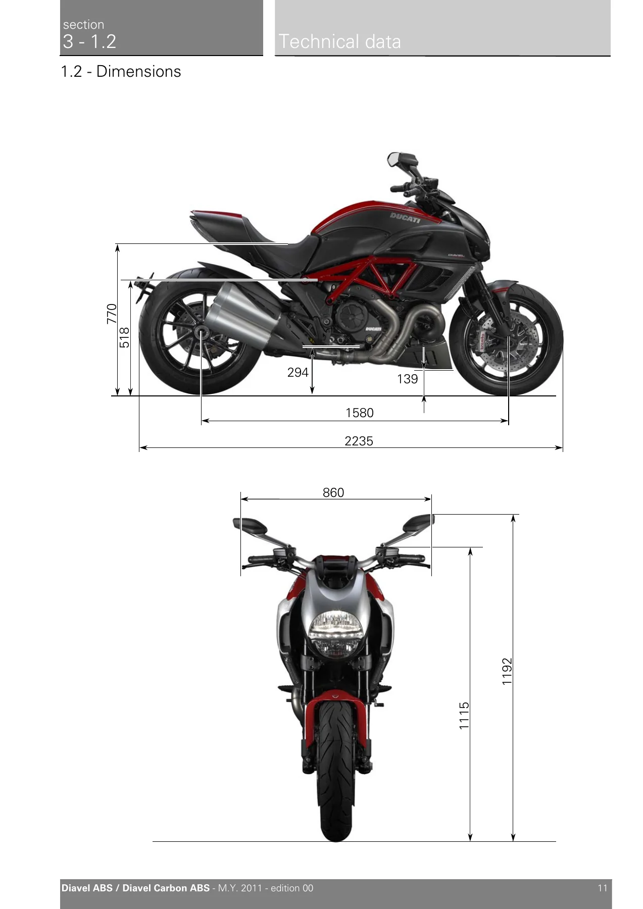
1.2 – Dimensionsp. 39
2 – Fuel, lubricants and other fluidsp. 40
3 – Torque settingsp. 41
Frame torque settingsp. 41
Engine torque settingsp. 48
4 – Service toolsp. 51
Specific tools for the enginep. 51
Specific tools for the framep. 58
Appropriate diagnosis toolsp. 61
4 – Maintenance operationsp. 65
1 – Vehicle pre-deliveryp. 67
2 – Scheduled maintenance chartp. 68
Operations to be carried out by the dealerp. 68
List of operations to be performed at 1000 kmp. 68
Operations to be carried out by the dealerp. 69
List of operations to be performed every 12000 km / year (first limit reached)p. 69
Operations to be carried out by the customerp. 69
List of operations to be performed every 1000 kmp. 69
3 – Maintenance operationsp. 70
Reading of the error memory with DDS on the engine control units, vehicle and ABSp. 70
Check engine oil levelp. 70
Changing the engine oil and filter cartridgep. 71
Checking valve clearancesp. 75
Change timing beltsp. 78
Spark plugs replacementp. 79
Changing and cleaning the air filtersp. 81
Checking the coolant levelp. 84
Changing the coolantp. 85
Changing the brake fluidp. 87
Draining the clutch hydraulic circuitp. 91
Filling the clutch circuitp. 94
Adjusting the steering head bearingsp. 96
Adjusting the chain tensionp. 97
Checking brake pad wear and changing brake padsp. 98
Adjusting the throttle cablep. 103
Adjusting the clutch lever and front brake leverp. 105
Adjusting the position of the gear change and rear brake pedalsp. 106
Adjusting the front forkp. 107
Adjusting the rear shock absorberp. 108
5 – Fairingsp. 111
1 – Rear view mirrorsp. 113
Removal of the rear-view mirrorsp. 114
Refitting the rear-view mirrorsp. 114
2 – Fairingsp. 115
Removal of the fuel tank fairingsp. 116
Disassembly of the front half-fairingsp. 119
Reassembly of the front half-fairingsp. 120
Refitting the fuel tank fairingsp. 122
3 – Seatp. 127
Removal of the seatp. 128
Disassembly of the seatp. 128
Reassembly of the seatp. 129
Refitting the seatp. 130
4 – Front and rear mudguardp. 131
Removal of the front mudguardp. 132
Refitting the front mudguardp. 134
Removing the rear mudguardp. 135
Refitting the rear mudguardp. 135
5 – Fairingsp. 136
Removal of belly fairingp. 137
Reassembly of belly fairingp. 140
6 – Electrical components supportp. 143
Removing the electrical components supportp. 144
Reassembling the electrical components supportp. 146
6 – Electric system and engine control systemp. 151
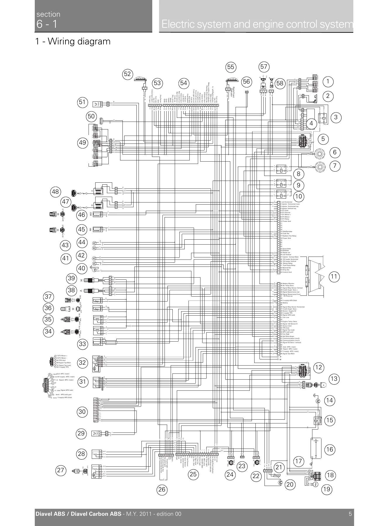
1 – Wiring diagramp. 155
Key to wiring diagramp. 156
Wiring diagram colour codesp. 157
Rear left fuse box (1) keyp. 157
Rear right fuse box (2) keyp. 157
Routing of wiring on framep. 158
2 – Battery charging systemp. 159
Checking the battery charging systemp. 159
Recharging the batteryp. 160
Topping up the electrolytep. 161
Batteryp. 165
Alternatorp. 169
Rectifier-regulatorp. 172
3 – Electric starting systemp. 174
Electric starting systemp. 174
Starter motorp. 174
Solenoid starterp. 179
4 – Lights and indicating devicesp. 181
Renewal of the headlightp. 181
Changing bulbsp. 185
Headlight aimp. 188
5 – Indicating devicesp. 189
Checking the indicating devicesp. 189
6 – Protection and safety devicesp. 194
Checking protection and safety device componentsp. 194
Checking the fusesp. 195
7 – Instrumentsp. 196
Instrument panelp. 196
Instrument panel systemp. 197
LCD unit functionsp. 199
Vehicle speed indicatorp. 200
Engine rpm indicator (RPM)p. 201
Clockp. 202
Coolant temperaturep. 203
Instrument panel on tankp. 204
TFT – Parameter setting/displayp. 204
Total distance covered indicator: “Odometer“p. 205
“Trip 1“ meterp. 206
“Trip 2“ meterp. 207
Distance travelled on fuel reserve: “TRIP FUEL“p. 207
Indicator “CONS. AVG“ – Average fuel consumptionp. 208
Indicator “CONS.“ – Instantaneous fuel consumptionp. 208
Indicator “SPEED AVG” – Average speedp. 209
Indicator “TRIP TIME“ – Trip timep. 209
Indicator “AIR” – Air temperaturep. 210
Engaged gear indicatorp. 210
“Riding Mode set“ indicationp. 211
Indication if the “LAP” function is active/not activep. 211
“Riding Style” function (riding style change)p. 212
Maintenance indicatorp. 213
First warning – OIL SERVICE 1000 Kmp. 213
Residual range indication when the SERVICE is duep. 214
Indication of range reached for SERVICEp. 214
Warning indication (Alarms/Signals)p. 215
“Low” battery levelp. 216
Traction Control (DTC) deactivatedp. 216
Hands Free key (HF) not recognisedp. 217
“Low“ Hands Free key (HF) battery levelp. 217
“High“ engine coolant temperaturep. 218
Steering release error – Steering still lockedp. 218
Instrument panel diagnosisp. 219
“Setting” menup. 221
“Riding Mode” customisationp. 223
DTC (Ducati Traction Control) setting functionp. 225
Tips on how to select the sensitivity levelp. 226
ENGINE setting function (Engine Power Control)p. 227
DEFAULT function (Resetting Ducati default parameters)p. 228
Menu 2 On/Off functionp. 229
Background setting function for the instrument panel on tank – DASHBOARD 1p. 230
Backlighting setting function for the instrument panel on handlebar – DASHBOARD 2p. 231
Digital RPM indication functionp. 232
LAP Activation/Deactivation function (lap time)p. 233
LAP registration functionp. 234
Stored LAP display functionp. 236
Stored LAP erase functionp. 237
Battery voltage indicator (BATTERY)p. 238
Clock setting functionp. 239
Units of measurement modification functionp. 240
ABS disabling functionp. 242
8 – The “Hands Free” systemp. 243
Introduction to the “Hands Free“ systemp. 243
Operating principlep. 243
How to turn the motorcycle onp. 244
How to switch the dashboard onp. 244
How to start the enginep. 245
How to start the motorcycle if the active key is not workingp. 246
How to start the motorcycle without keysp. 246
How to turn the motorcycle offp. 247
Recovery and emergency proceduresp. 249
Recovery procedure with no keyp. 249
Recovery in the event of flat active key batteryp. 250
Recovery procedure in the event of electric steering lock faultp. 250
Recovery procedure in the event of Hands Free system faultp. 251
Start procedure with PIN code (no keys)p. 251
How to enable engine start with PIN codep. 252
How to enable the PIN codep. 252
How to reset the PIN codep. 252
Wiring diagram of the Hands Free systemp. 253
Possible faults of the Hands Free system componentsp. 257
The Hands Free modulep. 257
Communication antennap. 259
On/off switch on handlebarp. 261
The Hands free relayp. 263
Active keyp. 264
Passive keyp. 267
Programming/reprogramming keysp. 268
9 – Introduction to the engine control systemp. 269
Specific operating strategiesp. 269
Inputs and outputs of engine control unit and connection to CAN networkp. 270
Layout of engine control system and other componentsp. 271
Removal of the control unitp. 272
Reassembly of the control unitp. 273
Fuel system circuitp. 275
Injection and ignitionp. 278
Operating principle and characteristics of the ride-by-wire systemp. 282
Explanation of the function of the ride-by-wire systemp. 287
Anti-pollution system and auto-adaptive strategyp. 289
Ignition coilsp. 294
Injectorsp. 298
Throttle valve operation enginep. 300
Engine start buttonp. 302
Clutch lever buttonp. 304
Side stand buttonp. 306
Injection relayp. 308
Throttle valve actuator motor relayp. 310
Starter motor relayp. 312
Radiator fan relayp. 314
Engine speed-timing sensorp. 316
Accelerator position sensor (throttle grip)p. 318
Throttle valve position sensorp. 320
Component assembling positionp. 320
Air temperature sensorp. 322
Engine temperature sensorp. 324
Absolute pressure sensorsp. 326
Oxygen sensorsp. 328
11 – Diagnostic instrumentsp. 332
Using a multimeter to check the electrical systemsp. 332
Description of the diagnosis instrument (DDS)p. 334
Tester power supplyp. 336
DDS diagnosis instrumentp. 339
Checking and adjusting timing belt tensionp. 340
Checking the idle speedp. 344
Check the idle and the CO amount with warm enginep. 344
Check the engine oil pressurep. 345
Cylinder compression testp. 349
Fuel pressure testp. 353
Guided diagnosisp. 357
Testing the battery charging systemp. 360
Deactivating the “service” indication on the instrument panelp. 363
ABS diagnosisp. 366
Icons tablep. 367
7 – Chassisp. 369
1 – Front wheelp. 373
Removal of the front wheelp. 374
Overhauling the front wheelp. 377
Refitting the front wheelp. 380
2 – Rear wheelp. 383
Removing of the rear wheelp. 384
Overhauling the rear wheelp. 384
Refitting the rear wheelp. 386
3 – Front brake controlp. 387
Removal of the front brake master cylinderp. 389
Refitting the front brake master cylinderp. 390
Maintenance operationsp. 392
Removal of the front brake systemp. 392
Removal of the brake discsp. 394
Overhauling the front brake componentsp. 394
Refitting the brake disksp. 394
Refitting the front brake systemp. 395
4 – Rear brakep. 398
Removing of the rear brake controlp. 400
Disassembly of the rear brake controlp. 402
Refitting the rear brake controlp. 403
Removal of the rear brake calliperp. 406
Removal of the rear brake discp. 407
Refitting the rear brake calliperp. 408
5 – ABS system informationp. 409
Operating principlep. 409
ABS system operating informationp. 410
ABS system deactivationp. 412
6 – System componentsp. 413
Replacing the front phonic wheel sensorp. 414
Replacing the rear phonic wheel sensorp. 416
Removing of the ABS control unitp. 418
Refitting the ABS control unitp. 419
Flexible wiring/hoses positioningp. 420
Table Ap. 421
Table Bp. 423
Table Cp. 428
7 – ABS components maintenancep. 434
Adjusting of the AIR-GAP phonic wheel sensorp. 434
Bleeding of the ABS hydraulic systemp. 436
8.1 – Handlebar unit: Throttle twistgripp. 437
Removal of the handlebarp. 438
Refitting the handlebarp. 439
Adjusting the throttle cablep. 440
Removal of the throttle twistgripp. 440
Refitting the throttle twistgripp. 441
8.2 – Handlebar unit: Hydraulic clutch controlp. 442
Removal of the clutch master cylinder assemblyp. 444
Refitting the clutch master cylinder assemblyp. 445
Removal of the clutch transmission unitp. 446
Refitting the clutch transmission unitp. 447
8.3 – Handlebar unit: Hands freep. 452
Removing the Hands Freep. 453
Refitting the Hands Freep. 454
9 – Gearchange mechanismp. 455
Removal of the gearchange controlp. 456
Disassembly of the gearchange mechanismp. 456
Refitting the gearchange mechanismp. 457
10.1 – Fork – Steering head: front forkp. 458
Removal of the front forksp. 459
Overhauling the front forksp. 460
Refitting the front forksp. 468
10.3 – Fork – steering head: Steeringp. 470
Adjusting the steering head bearingsp. 471
Steering angle adjustmentp. 472
Removal of the steering head componentsp. 473
Refitting the steering head componentsp. 477
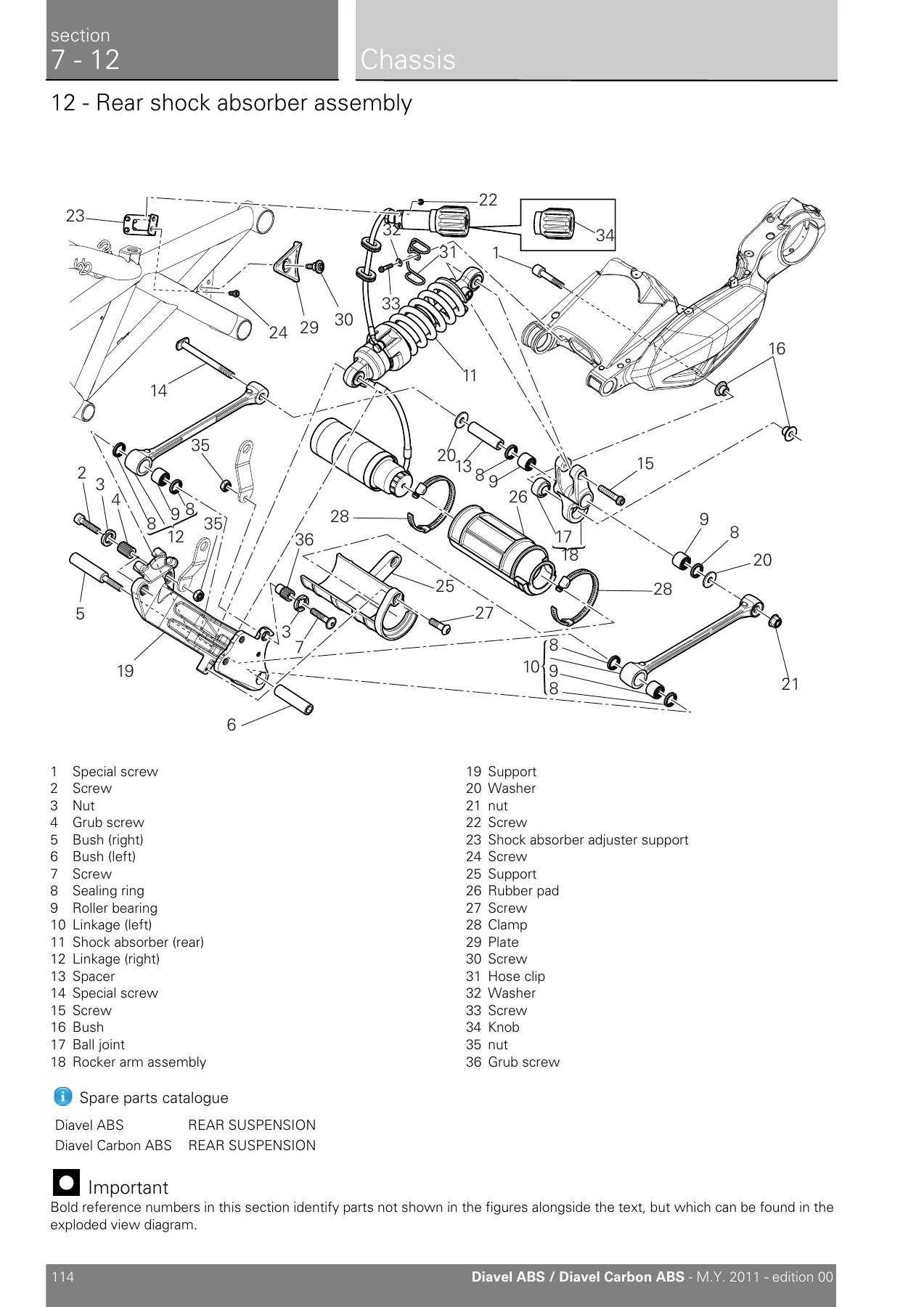
12 – Rear shock absorber assemblyp. 481
Rear suspension systemp. 482
Removal of the rear shock absorberp. 483
Overhauling the rear shock absorberp. 484
Disassembly of rear shock absorber – rocker arm – linkage assemblyp. 484
Reassembly of rear shock absorber – rocker arm – linkage assemblyp. 485
Refitting the rear suspensionp. 487
13 – Swingarmp. 489
Removal of the rear wheel eccentric hub and rear wheel shaftp. 491
Refitting the rear wheel eccentric hub and rear wheel shaftp. 493
Removal of the swingarmp. 497
Inspecting the swingarm pivotp. 500
Overhauling the rear swingarmp. 501
Refitting the swingarmp. 505
14 – Final drivep. 508
Inspecting the final drivep. 509
Removing of the front sprocketp. 510
Refitting the front sprocketp. 512
Replacing of the rear sprocketp. 514
Refitting the rear sprocketp. 515
Washing the chainp. 516
Lubricating the chainp. 516
15 – Footrest bracketsp. 517
Removal of the front footrestsp. 518
Refitting the front footrestsp. 519
Removing the front footrest bracketsp. 520
Reassembling the front footrest bracketsp. 521
Removing of the rear footrestsp. 522
Refitting the rear footrestsp. 523
16 – Standsp. 526
Removing of the side standp. 527
Refitting the side standp. 530
17 – Frame inspectionp. 531
Disassembly of structural components and the framep. 533
Removal of the tool trayp. 535
Removing the frame and the lateral footrestsp. 536
Checking the framep. 537
Reassembly of structural components and the framep. 538
Reassembling the frame and the lateral footrestsp. 543
Reassembly of the tool trayp. 546
18 – Tail light – number plate holderp. 547
Removal of the licence plate holderp. 548
Refitting the number plate holderp. 549
Removal of the tail lightp. 549
Refitting the tail lightp. 550
8 – Fuel system / Exhaust systemp. 551
2 – Fuel tankp. 553
Removal of the fuel tankp. 554
Removal of the fuel tank filler capp. 556
Refitting the filler capp. 557
Replacing the tank flange and fuel sensorp. 558
Refitting the fuel tank flangep. 559
Refitting the fuel tankp. 559
6 – Airbox – Throttle Bodyp. 568
Removal the airbox and throttle bodyp. 569
Refitting the airbox and throttle bodyp. 577
7 – Air intakep. 583
Removal of the air filtersp. 584
Refitting the air filtersp. 586
8 – Exhaust systemp. 588
Removing the silencerp. 590
Removal of the exhaust systemp. 591
Refitting the exhaust systemp. 594
Refitting the silencerp. 598
10 – Evaporative emissions canisterp. 599
Evaporative emissions canister system (USA versions only)p. 600
Removal of the evaporative emissions canisterp. 601
Refitting the evaporative emissions canisterp. 603
9 – Enginep. 609
1 – Removal-refitting of the engine assemblyp. 613
Removal of the enginep. 614
Refitting the enginep. 616
2.1 – Lubrication system: oil pumpp. 618
Removal of the oil pumpp. 619
Disassembly of the oil pumpp. 620
Reassembly of the oil pumpp. 621
Refitting the oil pumpp. 621
2.2 – Lubrication system: oil coolerp. 623
Removal of the lubrication systemp. 624
Oil cooler inspectionp. 626
Refitting the lubrication systemp. 626
3.1 – Cooling system: coolant expansion tankp. 629
Removal of the expansion tankp. 631
Refitting the expansion tankp. 632
Removal of the cooling system hoses and unionsp. 637
Refitting the cooling system hoses and unionsp. 640
3.2 – Cooling system: water radiatorsp. 651
Removing the water radiatorsp. 653
Disassembling the water radiator unitp. 656
Renewal of the cooling fanp. 658
Reassembling the water radiator unitp. 658
Refitting the radiatorp. 659
3.3 – Cooling system: water pumpp. 662
Removal of the water pumpp. 663
Refitting the water pumpp. 665
4.1 – Cylinder head assemblies: checks and adjustmentsp. 669
Checking and adjusting the valve clearancesp. 670
Checking valve liftp. 672
Checking the engine timingp. 673
4.2 – Cylinder head assemblies: timing systemp. 677
Removal of the timing belt coversp. 678
Removal of the movable tensioner/timing beltp. 680
Removing of the cylinder head pulley/fixed tensionerp. 680
Removal of the tensioner and idler pulley mounting studsp. 681
Disassembly of the camshaft pulleysp. 681
Removing the timing belt driveshaft pulleysp. 682
Refitting the timing belt driveshaft pulleysp. 683
Refitting the idler and tensioner pulley mounting studsp. 685
Reassembly of the timing pulleysp. 686
Refitting the cylinder heads pulleys/fixed tensionersp. 687
Refitting the timing beltsp. 689
Refitting the timing coversp. 695
4.4 – Cylinder head assemblies: camshaftsp. 697
Removal of the camshaftsp. 699
Checking the camshafts and supportsp. 701
Refitting the camshaftsp. 702
Removal of the intake manifold and coolant unionp. 709
Refitting the intake manifold and coolant unionp. 711
4.5 – Cylinder head assemblies: valves – rocker armsp. 713
Removal of the cylinder headsp. 714
Removing the valvesp. 715
Removing the valve rocker armsp. 716
Overhaul of cylinder head componentsp. 719
Reassembly of the cylinder headp. 726
Refitting the cylinder head assembliesp. 734
5 – Cylinder/piston assembliesp. 736
Removal of the cylinder/piston assemblyp. 737
Overhaul of the cylinder barrel/piston componentsp. 740
Refitting the cylinder/piston assemblyp. 745
6.1 – Clutch assembly: clutchp. 750
Description of the clutch assemblyp. 751
Removal of the clutchp. 752
Checking and overhauling the componentsp. 755
Reassembling the clutchp. 757
6.2 – Clutch assembly: clutch coverp. 761
Removal of the clutch-side crankcase coverp. 762
Disassembly of the clutch coverp. 763
Reassembly of the clutch-side crankcase coverp. 764
Refitting the clutch-side crankcase coverp. 765
6.3 – Clutch assembly: primary drive gearsp. 766
Removal of the primary drive gearp. 767
Refitting the primary drive gears and checking backlashp. 769
7.1 – Gearbox assembly: gearchange mechanismp. 772
Removal of the gear selector leverp. 773
Disassembly of gear interlock plunger and pawl assemblyp. 775
Refitting the gear interlock plunger and pawl assemblyp. 776
Refitting the gear selector leverp. 778
7.2 – Gearbox assembly: gearbox shaftsp. 781
Removal of the gearbox assemblyp. 783
Disassembly of the gearbox shaftsp. 786
Overhaul of the gearboxp. 795
Inspection of the gear selector forksp. 796
Inspection of the gear selector drump. 797
Reassembly of the gearbox shaftsp. 798
Reassembly of the gearboxp. 802
8 – Flywheel – alternatorp. 803
Removal of the generator coverp. 804
Disassembly of the generator coverp. 806
Removing the flywheel – generator assemblyp. 807
Overhaul of the flywheel-alternator assemblyp. 809
Refitting the flywheel-alternator assemblyp. 815
Refitting the alternator-side crankcase coverp. 817
9.1 – Crankcase assembly: external componentsp. 821
Removing outer componentsp. 823
Refitting the external componentsp. 827
Removal of the timing gearsp. 833
Refitting the timing gearsp. 835
Removal of the starter motor idler gearp. 837
Refitting the starter motor gearp. 838
9.2 – Crankcase assembly: crankcase halvesp. 839
Separation of the crankcase halvesp. 841
Overhaul of the crankcase halvesp. 844
Main bearingsp. 847
Reassembly of the crankcase halvesp. 850
Shimming the shaftsp. 853
Reassembly of the crankcase halvesp. 856
9.3 – Crankcase assembly: crankshaft/connecting rods assemblyp. 864
Removal of the crankshaft/connecting rods assemblyp. 865
Disassembly of the crankshaft/connecting rods assemblyp. 866
Overhaul of the connecting rodsp. 867
Reassembly of the connecting rodsp. 871
Refitting the crankshaft/connecting rod assemblyp. 875

Across these nine sections the manual moves from the information a technician needs before touching the bike – identification stampings, fluid types, fastener torque tables and the scheduled maintenance chart – through to complete strip-down of the engine, with each procedure giving the removal sequence, the special tool required, the tightening torque and the refitting order. The electrical material is unusually thorough for a workshop manual: it includes the complete wiring diagram with colour codes and fuse-box keys, the Hands Free passive/active key and PIN code recovery procedures, the ride-by-wire throttle system with APS and TPS testing, and the DDS diagnostic routines used to read errors, activate actuators, check belt tension, and measure oil pressure, fuel pressure and cylinder compression.

What a Technician Can Actually Do With This Manual

Every chapter is written as a repair procedure, not a description. The maintenance section lists exactly which operations the dealer performs at 1,000 km and at every 12,000 km / year interval, and which ones the owner is expected to handle. The chassis and engine sections give the component-by-component teardown order with the tooling called out – service tools 88713.xxxx and 88765.xxxx, plus the DDS tester – so a workshop can quote the job, order the right special tools and work to the same tolerances Ducati specified for the model. Torque settings are split between frame and engine, and safety-critical fasteners are marked as needing to fall within a tight tolerance.

Why It Matters on This Motorcycle

The Diavel ABS and Diavel Carbon ABS share a 1,198 cm³ 90° L-twin with desmodromic valve gear driven by toothed belts, a ride-by-wire throttle, ABS with phonic-wheel speed sensors and a Hands Free keyless starting system. None of these is guess-friendly. Timing belt tension is checked with a DDS belt-tension sensor and read in Hz, valve clearances are adjusted with replaceable shims, and the ABS air-gap is measured with a feeler gauge at four points around the wheel. Working without the numbers and the sequences in this manual means guessing, and guessing on a desmo engine or an ABS-equipped braking system is expensive.

Diagnostics, Hands Free and the DDS Workflow

Model-specific detail that is hard to find elsewhere is present throughout Section 6. The Hands Free system – keyless start, the electric steering lock, the active key with its internal CR 2032 battery and the passive transponder key – is documented with the recovery procedures for a flat key battery, a locked steering pin or a CAN communication failure, plus the PIN code start sequence and the key programming and reprogramming routine. The engine control chapter covers the fuel system circuit, the speed-density and throttle-angle strategies, the self-adaptive parameters and their reset procedure, and the oxygen sensor closed-loop logic. Diagnostic work is supported by the DDS instrument procedures for guided diagnosis, error memory reading, belt tension measurement, idle and CO checking, oil pressure and fuel pressure tests and cylinder compression testing.

IMAGES PREVIEW

2011 Ducati Diavel 1200 Carbon ABS Service Manual - Workshop Repair PDF — PDF page 39 preview
2011 Ducati Diavel 1200 Carbon ABS Service Manual - Workshop Repair PDF — PDF page 155 preview
2011 Ducati Diavel 1200 Carbon ABS Service Manual - Workshop Repair PDF — PDF page 481 preview

Instant PDF Delivery

The 2011 Ducati Diavel 1200 Carbon ABS Service Manual is supplied as an instant-download PDF – no shipping, no waiting. Once the order is complete the file is available immediately and can be read on a laptop, tablet or phone in the workshop, or printed page by page for the jobs you are doing. Search the file for a torque value, a fault code or a component name and jump straight to the procedure instead of hunting through a paper binder.
Reviews

There are no reviews yet.

Be the first to review “2011 Ducati Diavel 1200 Carbon ABS Service Manual – Workshop Repair PDF”

What Our Customers Say

★★★★★ Live reviews from customers
Loading customer reviews...
0
    0
    Your Cart
    Your cart is emptyReturn to Shop
    🛒
    Recently Purchased
    🕒 verified order