
2016 IAE V2500 Line and Base Maintenance Technical Training Manual – PDF
Original price was: $39.95.$24.95Current price is: $24.95.
Comprehensive 724-page IAE V2500 Line and Base Maintenance Technical Training Manual from April 2016. Covers engine overview, power plant, fuel system, FADEC, power management, engine construction, heat management, compressor airflow control, secondary air systems, ice protection, indicating, starting and ignition, thrust reverser, and troubleshooting for the V2500 turbofan engine family.
Description
IAE V2500 Line and Base Maintenance Technical Training Manual – 2016 Edition
This IAE V2500 Line and Base Maintenance Technical Training Manual is a 724-page technical training document published in April 2016 (document number 544). It provides comprehensive system knowledge for the V2500 turbofan engine family, covering everything from basic engine architecture and station numbering through to FADEC electronic engine control, fuel metering, thrust reverser operation, and fault isolation procedures. The manual is intended for maintenance training and provides detailed descriptions, system schematics, component illustrations, and operational explanations across all major engine systems.
File Details
- Manual Type: Line and Base Maintenance Technical Training Manual
- Manufacturer: International Aero Engines (IAE)
- Engine Model: V2500 turbofan engine family
- Language: English
- Page Count: 724 pages
- File Format: PDF
- Publication Date: April 2016
- Document Number: 544
Chapters Covered
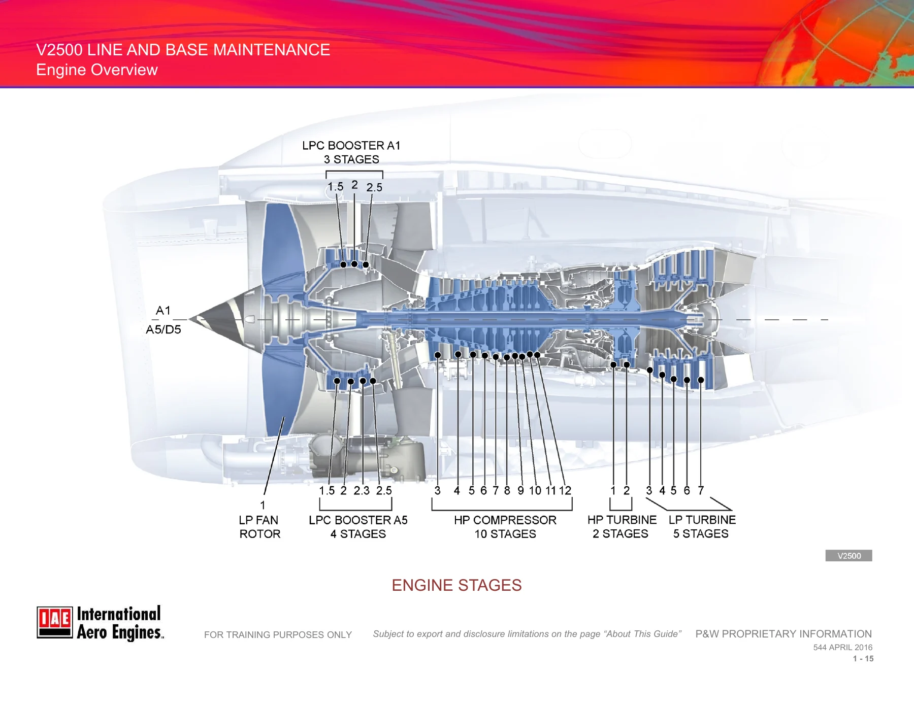
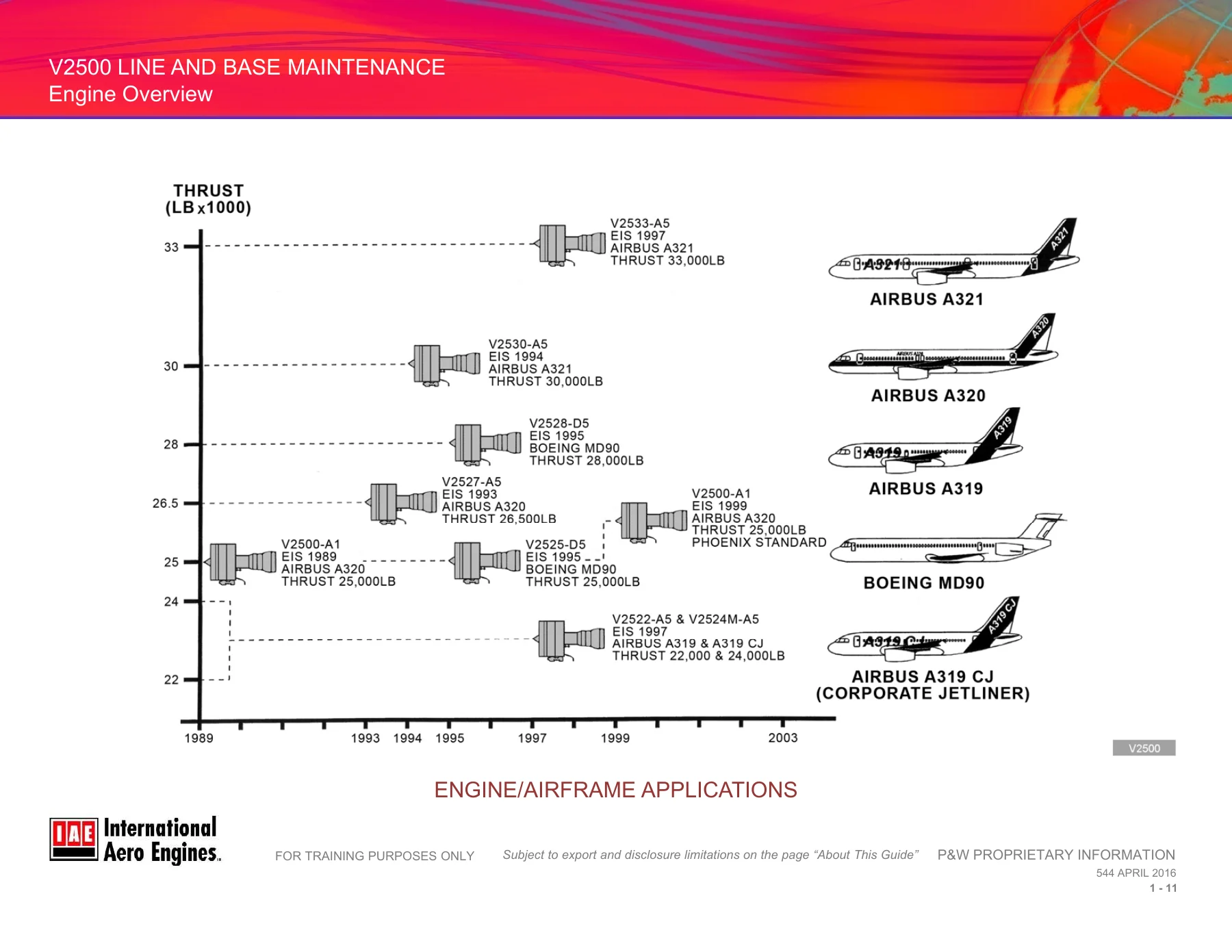
- Chapter 1 – Engine Overview: Common design features, engine specifications, stations, stages, flanges, borescope ports, module developers, V2500 engine description, engine/airframe applications, stage numbering, and borescope access ports and plugs.
- Chapter 2 – Power Plant ATA 71: Nacelle components including air intake cowl, fan cowl doors, thrust reverser C-ducts, mixed exhaust system, nacelle access panels, airframe interface components, engine electrical harnesses, front and rear engine mounts, Engine Combined Drains System, leakage limits, and engine storage.
- Chapter 3 – Fuel and Engine Control ATA 73: Fuel system overview, fuel circulation, fuel system components, engine control system overview, Electronic Engine Control (EEC), EEC electrical harness and pressure connections, Data Entry Plug (DEP), Engine Dedicated Alternator (EDA), and Engine Interface Unit (EIU).
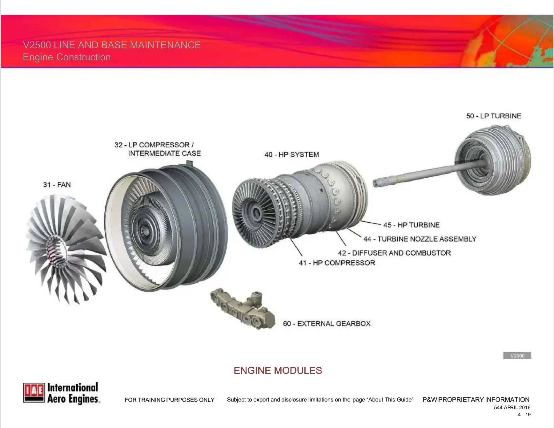
- Chapter 4 – Engine Construction ATA 72: Engine main bearings, bearing compartments (front, center, rear), internal cooling and sealing airflows, engine modules including fan, LPC/intermediate case, HPC, diffuser and combustor, turbine nozzle guide vane assembly, HPT, LPT, Turbine Exhaust Case (TEC), and external gearbox assembly.
- Chapter 5 – Electronic Engine Control ATA 73: Engine control operations, EEC purpose and operation, Data Entry Plug, EEC electrical harness and pressure connections, Engine Dedicated Alternator, EEC interfaces, failures and redundancy, and failsafe positions.
- Chapter 6 – Power Management ATA 76: Throttle control system, throttle control mechanism, bump rating push button, Flexible Take-Off (FLX), EEC/fuel system interface, basic control loop (EPR/N1 closed loop control), alternate engine control (N1 rated and unrated modes), and thrust modes (auto, memo, manual).
- Chapter 7 – Fuel ATA 73: Fuel system overview, fuel circulation, fuel pump (LP and HP stages), Fuel Cooled Oil Cooler (FCOC), Low Pressure fuel filter, Fuel Metering Unit (FMU), fuel flow transmitter, Fuel Distribution Valve (FDV), fuel distribution manifolds, Fuel Spray Nozzles (FSNs), fuel temperature sensor, fuel filter differential pressure switch, and fuel indications.
- Chapter 8 – Oil System: Oil system overview, oil tank, oil pressure pump and filter assembly, Fuel Cooled Oil Cooler, bearing compartment lubrication (front, center, rear), external gearbox lubrication, scavenge pump unit, deoiler, magnetic chip detectors, oil system indications, and related sensors and switches.
- Chapter 9 – Heat Management System ATA 73: ACOC Air Modulating Valve (AMV), ACOC Electro Hydraulic Servo Valve (EHSV), Integrated Drive Generator Fuel Cooled Oil Cooler (IDG FCOC), Fuel Diverter and Return-to-Tank Valve (FDRV), and Heat Management System modes 1, 3, 4, and 5.
- Chapter 10 – Compressor Airflow Control System ATA 75: Booster Stage Bleed Valve (BSBV) for A1 and A5 engines, BSBV master and slave actuators, Variable Stator Vane (VSV) system, Variable Stator Vane Actuator (VSVA), 7th and 10th stage HPC bleed valves, solenoid valves, hung and hot starts, and engine climb, cruise, and transient operation.
- Chapter 11 – Secondary Air Systems ATA 75: Active Clearance Control (ACC) system, ACC actuator, HPT/LPT ACC air valves, HPT/LPT ACC manifold and tube assemblies, 10th Stage Make-up Air System, Aircraft Services Air Off-Take System, and Air Cooled Air Cooler (ACAC).
- Chapter 12 – Ice Protection ATA 30: Ice protection overview, Thermal Anti-Icing (TAI) control valve, TAI valve manual override procedure, P2/T2 probe heater, spinner ice protection, and ECAM indications.
- Chapter 13 – Indicating ATA 77: ECAM indications (upper and lower screens), ECAM system fault monitoring, ECAM flight phase displays, N1 speed indicating system, N2 speed indicating system, Exhaust Gas Temperature (EGT) indicating system, P3/T3 sensor, Engine Pressure Ratio (EPR) indicating system, P2/T2 sensor, P4.9 sensor, and engine vibration indicating system.
- Chapter 14 – Starting and Ignition ATA 80/74: Starting system, starter air duct, starter air control valve, pneumatic starter motor, starting electrical control, Engine Interface Unit (EIU), engine start control panels, ignition system, engine relay box, ignition exciters, ignition cables, igniter plugs, auto start procedure, manual start procedure, dry and wet motoring, starter motor duty cycle limits, and engine start fault ECAM indications.
- Chapter 15 – Thrust Reverser ATA 78: Thrust reverser system components, operation (deploy and stow), hydraulic system, Hydraulic Control Unit (HCU), lower locking actuators, upper non-locking actuators, shut-off valve, manual bypass non-return valve, flex (synchronization) shaft, cascades, system deactivation for maintenance and flight, manual deploy and stow, power deploy and stow, and lock proximity sensor.
- Chapter 16 – Troubleshooting ATA 31: Fault message types, ECAM Class 1, 2, and 3 fault messages, Multipurpose Control and Display Unit (MCDU), Post Flight Report (PFR), Centralized Fault Display System (CFDS), fault acronyms (Track Check, Input Latch, Wrap Around Failure, Crosscheck Failure), accessing fault data using the MCDU, locating troubleshooting procedures, and using AirN@v.
This IAE V2500 technical training manual delivers a complete system-by-system education on the V2500 turbofan engine, covering both the A1 and A5 engine variants as well as the D5 series. The document walks through engine architecture, module construction, fuel and oil systems, FADEC electronic control, power management, thrust reverser hydraulics, starting and ignition, ice protection, and indicating systems. Each chapter provides component descriptions, operational explanations, system schematics, and cross-references to ATA chapters, making it a valuable reference for maintenance training, system familiarization, and fault isolation preparation.
What This Manual Enables You To Do
- Understand V2500 engine architecture, station numbering, stage numbering, flange designations, and borescope access locations for both A1 and A5 engines.
- Identify and locate major engine modules including fan, LPC/booster, HPC, diffuser and combustor, HPT, LPT, Turbine Exhaust Case, and external gearbox.
- Understand the Fuel System from tank to combustor, including the LP and HP fuel pumps, FCOC, fuel filter, FMU, fuel flow transmitter, distribution valve, manifolds, and spray nozzles.
- Explain FADEC architecture, EEC channel operation, redundancy, failsafe positions, Data Entry Plug configuration, Engine Dedicated Alternator power generation, and EIU interface functions.
- Describe power management from throttle resolver angle through to EPR/N1 closed loop control, including auto thrust, memo mode, manual mode, alpha floor protection, and flexible take-off.
- Understand Heat Management System modes 1, 3, 4, and 5, including FDRV operation, ACOC air modulating valve control, and IDG FCOC function.
- Explain Compressor Airflow Control including BSBV operation, VSV system actuation, 7th and 10th stage bleed valve operation, and their role in surge prevention and engine starting.
- Describe Secondary Air Systems including Active Clearance Control, 10th Stage Make-up Air, Aircraft Services Air Off-Take, and the Air Cooled Air Cooler.
- Understand Ice Protection including TAI valve operation, manual override, P2/T2 probe heating, and spinner ice protection.
- Interpret ECAM indications for engine parameters including EPR, EGT, N1, N2, fuel flow, oil pressure, oil temperature, vibration, and nacelle air temperature.
- Explain Starting and Ignition systems including starter air valve operation, pneumatic starter motor engagement, ignition exciter operation, auto and manual start procedures, and starter duty cycle limits.
- Describe Thrust Reverser operation including HCU deploy and stow modes, locking actuator operation, proximity sensor feedback, and manual deployment procedures.
- Perform fault isolation using ECAM warnings, Post Flight Report data, CFDS interrogation via MCDU, fault acronyms, and AirN@v troubleshooting procedures.
Why This Manual Matters
Correct maintenance and troubleshooting of the IAE V2500 engine depends on a thorough understanding of its systems, components, and control logic. This training manual provides that foundation with clear explanations of how each system works, how components interact, and what happens during normal and abnormal operation. The detailed system descriptions and operational sequences help maintenance personnel diagnose faults accurately, understand EEC control logic, and perform maintenance tasks with confidence. The troubleshooting chapter provides a structured approach to fault isolation using ECAM, PFR, CFDS, and MCDU data, which is essential for efficient line and base maintenance.
IMAGES PREVIEW
Instant PDF Delivery
This IAE V2500 Line and Base Maintenance Technical Training Manual is delivered as an instant PDF download after payment. There is no shipping, no waiting for a physical copy, and no restrictions on how many times you access the file. The PDF can be viewed on any device including laptops, tablets, and smartphones, and pages can be printed for use in the hangar, classroom, or maintenance facility. Whether you are training new personnel, refreshing your own system knowledge, or preparing for troubleshooting tasks, this manual provides the technical depth you need in a convenient, searchable PDF format.
Reviews
There are no reviews yet.