
90Z6 Wheel Loader Shop Manual – Function & Structure PDF (93213-00760)
Original price was: $39.95.$23.95Current price is: $23.95.
Function & Structure shop manual for the 90Z6 wheel loader, covering controllers, ECM, hydraulic and electrical systems, and the operation of every major component from the main pump to the axle. 406-page PDF, document number 93213-00760.
Description
File Details
- Manual type: Shop Manual (Function & Structure)
- Document number: 93213-00760
- Machine: 90Z6 wheel loader
- Engine covered: Cummins QSM11
- Language: English
- File format: PDF
- Length: 406 pages
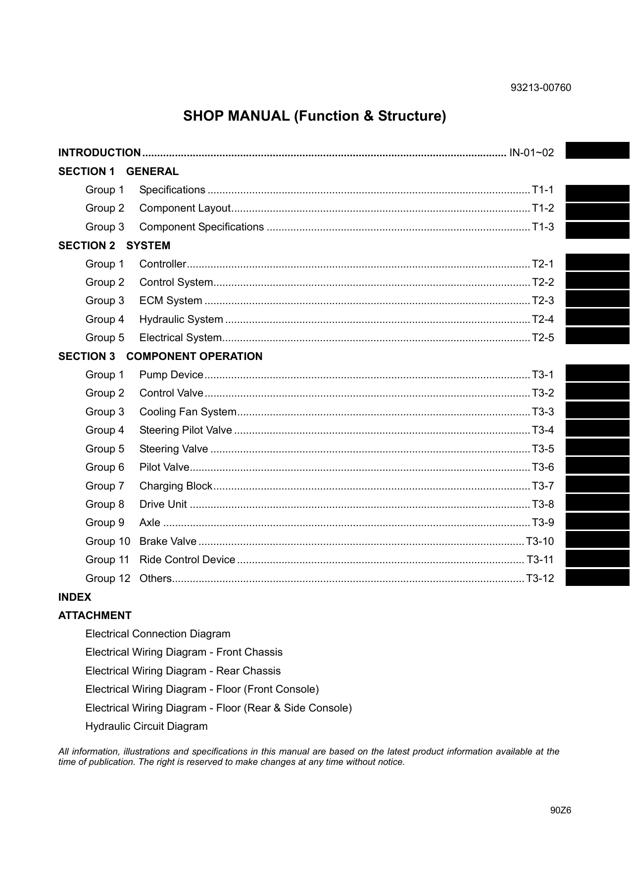
- Structure: Section 1 General, Section 2 System, Section 3 Component Operation, plus electrical and hydraulic diagram attachments
Chapters Covered
- Section 1 — General
- Group 1 Specifications (machine specifications, weight of main components)
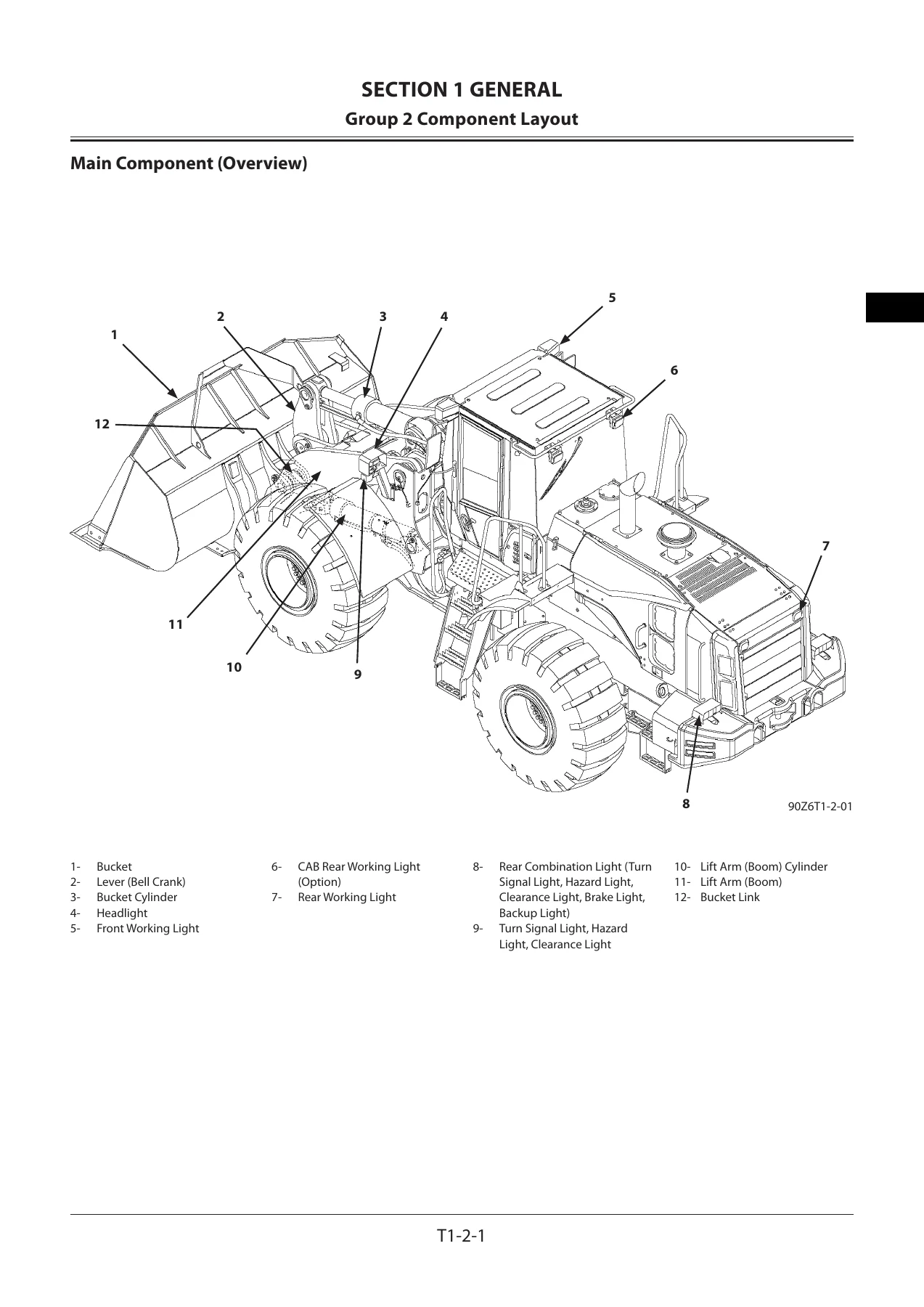
- Group 2 Component Layout (main component overview, travel system, electrical layout overview, cab, controllers and relays, right console, monitor and switches, monitor panel, engine and fan pump, transmission and torque converter, hydraulic pump device, multiple control valve, charging block, front axle, steering valve, brake valve, fan motor, pilot valve, ride control group, secondary steering group and pump)
- Group 3 Component Specifications (engine, engine accessories, hydraulic components, electrical components)
- Section 2 — System
- Group 1 Controller (outline, CAN circuit)
- Group 2 Control System (engine control, accelerator pedal control, auto-warm up, engine load idle speed, forward/reverse operation engine speed limiter, engine speed regulator for digging, speed limit with power mode off, machine overheat limiter, reversing fan idle speed, pump control, base torque control, torque decrease while dumping bucket, transmission control, neutral control, forward/reverse lever priority, manual and automatic speed shift, downshift, speed shift delay, declutch, shift holding, fan speed and reverse rotation control, ride control, transmission alarm, low brake oil pressure indicator, low steering oil pressure indicator, overrun alarm, lift arm auto leveler height and lower kickout, quick power mode, secondary steering, bucket auto leveler, lift arm float, lift arm kickout)
- Group 3 ECM System (outline, fuel injection control, operation of fuel injection, fuel flow diagram)
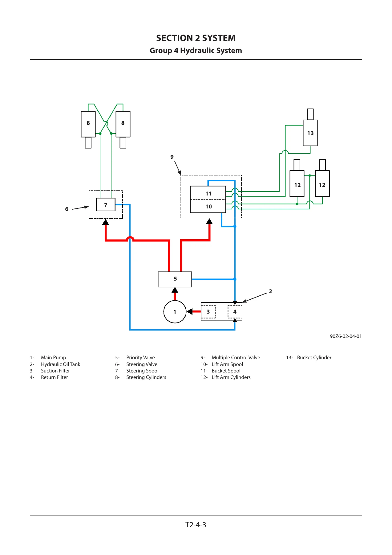
- Group 4 Hydraulic System (main circuit, priority valve circuit, neutral circuit, single and combined operation circuits, pilot circuit, charging circuit, lift arm and bucket operation control, pump control circuit, service brake circuit, parking brake circuit, ride control circuit, steering circuit, steering shock dampening, steering stop circuit, secondary steering circuit, fan speed control circuit, reversing fan circuit)
- Group 5 Electrical System (outline, main circuit, CAN circuit, electric power circuit, starting circuit, charging circuit, surge voltage prevention, engine stop circuit, accessory circuit, head light, hazard light, turn signal, horn, reverse light and buzzer, brake light, parking brake, working light, wiper, cab light circuits)
- Section 3 — Component Operation
- Group 1 Pump Device (main pump, regulator control functions, steering priority valve, steering main relief valve, pilot pump, pump delivery pressure sensor)
- Group 2 Control Valve (multiple control valve layout and cross sections, main relief valve, overload relief valve with make-up function, restriction valve, pump control valve, flow rate control valve)
- Group 3 Cooling Fan System (fan pump, fan motor, fan valve, normal and reverse rotation, fan speed control, make-up function, circuit pressure sensor)
- Group 4 Steering Pilot Valve (Orbitrol structure and operation)
- Group 5 Steering Valve (operation, steering overload relief valve, steering accumulator)
- Group 6 Pilot Valve (fingertip control pilot valve, electromagnetic detent, auxiliary pilot valve)
- Group 7 Charging Block (priority valve, pilot relief valve, parking brake solenoid valve, pump torque control solenoid valve, service brake and pilot accumulators, pressure sensors)
- Group 8 Drive Unit (torque converter, transmission, clutch packs, power flow through all forward speeds and reverse, transmission control valve, regulator valve, parking brake and manual release)
- Group 9 Axle (differential, torque proportioning differential, limited slip differential, service brake, final drive planetary)
- Group 10 Brake Valve (component layout, operation, stop lamp pressure switch, declutch pressure sensor)
- Group 11 Ride Control Device (ride control valve, charge-cut spool, overload relief valve, accumulator, lift arm raise pressure sensor, lift arm angle sensor)
- Group 12 Others (propeller shafts, stop valve, secondary steering pump and check block, axle oil cooler)
- Attachment Diagrams
- Electrical connection diagram
- Electrical wiring diagram — front chassis
- Electrical wiring diagram — rear chassis
- Electrical wiring diagram — floor (front console)
- Electrical wiring diagram — floor (rear and side console)
- Hydraulic circuit diagram
This 90Z6 wheel loader shop manual is written around function and structure rather than disassembly sequences, which makes it the volume you reach for when you need to understand why a system behaves the way it does before you touch it. Every controller on the machine is identified and its role explained — the main controller that manages engine speed, transmission, pumps and valves, the engine control module that handles fuel injection, the information controller, the column monitor controller and the air conditioner controller — along with the CAN network that ties them together and the termination resistors at each end of the bus.
What the System Section Gives You
Section 2 walks through each control strategy in turn and explains the input signals, the conditions that activate it and the conditions that switch it off. That includes the engine side (accelerator pedal control and its failure backup behaviour, auto-warm up, engine load idle speed control, the forward/reverse operation engine speed limiter, engine speed regulator for digging, speed limit control with power mode off, machine overheat limiter and reversing fan idle speed control) and the transmission side (neutral control, forward/reverse lever priority, manual and automatic speed shift, downshift, shift delay, declutch, shift holding). Reference graphs showing engine speed against pedal position or operating time accompany the explanations.
The hydraulic system section covers the main circuit, priority valve circuit, neutral circuit, single and combined operation circuits, the full pilot circuit, charging circuit, pump control circuit, service and parking brake circuits, ride control circuit, steering circuit with its shock dampening and stop functions, secondary steering circuit and fan circuits. The electrical system section works through the main circuit, starting, charging, surge voltage prevention and engine stop circuits, then the accessory circuits for lighting, hazard, turn signal, horn, reverse light and buzzer, brake light, parking brake, working lights, wipers and cab light.
What the Component Operation Section Gives You
Section 3 explains how each assembly is built and how it behaves internally. The pump device chapter covers the swash plate type main pump, the regulator and its four control functions, the steering priority valve and main relief valve, and the pilot pump. The control valve chapter covers the multiple control valve, main relief valve, overload relief valve with make-up function, restriction valves, negative control pump control valve and flow rate control valve, including combined lift arm and bucket operation.
The drive unit chapter deals with the torque converter, the transmission gear pattern and gear tooth counts, clutch pack construction and operation, power flow through each forward speed and reverse, the transmission control valve and its modulation behaviour, the regulator valve and the parking brake with its manual release procedure. The axle chapter explains the differential principle, torque proportioning differential, the optional limited slip differential, the wet multi-disc service brake and the final drive planetary. The charging block chapter details the brake priority valve, pilot relief valve, parking brake solenoid valve, pump torque control solenoid valve and the service brake and pilot accumulators.
Diagram Attachments
Beyond the numbered illustrations inside the chapters, the manual carries a set of full diagram attachments: an electrical connection diagram, electrical wiring diagrams split by front chassis, rear chassis, floor front console and floor rear and side console, and a hydraulic circuit diagram. These are the pages you keep open when tracing a harness or following oil through the machine.
Who This Manual Suits
Owners and operators of the 90Z6 who want to understand how the machine is meant to behave; technicians diagnosing control, hydraulic, transmission or electrical faults who need the logic behind a symptom; and workshops preparing for hydraulic or transmission work where knowing how a spool, regulator or clutch pack actually functions saves hours of guesswork. The specifications chapter supplies the machine dimensions and the weight of every major component, which is useful before lifting anything.
Because this is a function and structure volume, it explains operation rather than giving step-by-step removal and installation procedures. It pairs naturally with the workshop and engine manuals, and it is the reference that tells you what should be happening inside a system before you decide what is wrong with it.
IMAGES PREVIEW
Instant PDF Delivery
The 90Z6 wheel loader shop manual is delivered as an instant PDF download — no shipping, no waiting, no physical book to keep track of. Read it on a laptop or tablet in the workshop, print the circuit diagrams and specification pages you need for the job, or keep the whole document on a phone for quick reference at the machine. Whether you are chasing a control system fault, studying the hydraulic circuit before a repair, or simply want the correct dimensions and component weights before a lift, this manual puts the information in your hands the moment payment clears.
Reviews
There are no reviews yet.