
Aichi SK200 Truck Mounted Aerial Lift Service Manual SME-318A
Original price was: $34.95.$20.95Current price is: $20.95.
Comprehensive service and maintenance manual for the Aichi SK200 truck mounted aerial lift. Covers electric systems, hydraulic circuits, work range control, inspection procedures, and full adjustment data for the Mitsubishi FE445EVHX chassis.
Description
Aichi SK200 Service Manual — Complete Technical Coverage
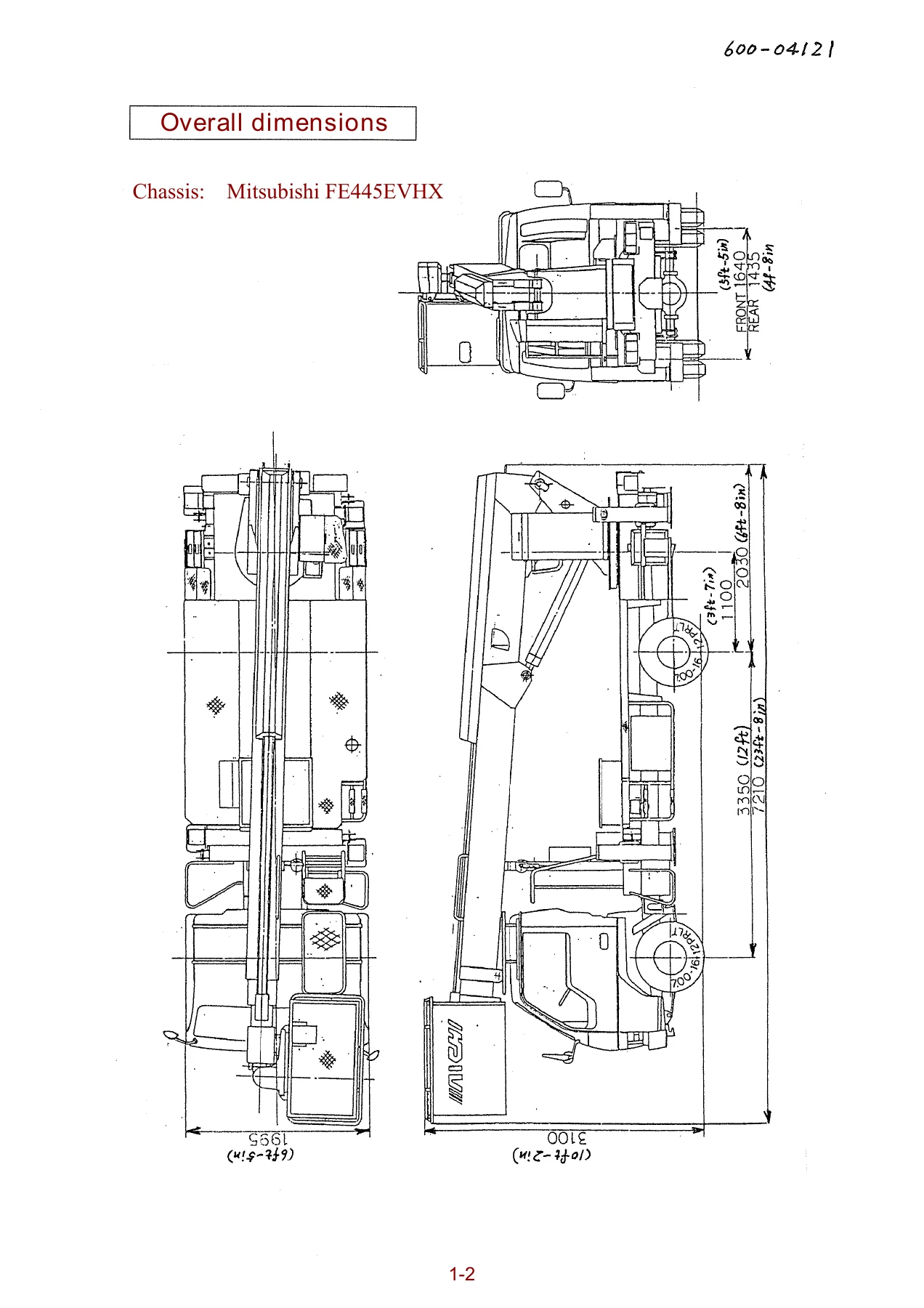
This Aichi SK200 Truck Mounted Aerial Lift Service Manual (document SME-318A) delivers the full adjustment and servicing procedures required to maintain, diagnose, and repair the SK200 aerial lift. Published by Aichi Corporation’s Customer Service Division, the manual covers the Mitsubishi FE445EVHX chassis and provides detailed electrical schematics, hydraulic circuit diagrams, work range control system calibration, and comprehensive inspection and maintenance schedules.
File Details
- Manual Type: Service Manual
- Brand / Model: Aichi SK200 Truck Mounted Aerial Lift
- Document Number: SME-318A
- Language: English
- Page Count: 102 pages
- File Format: PDF
- Chassis Covered: Mitsubishi FE445EVHX
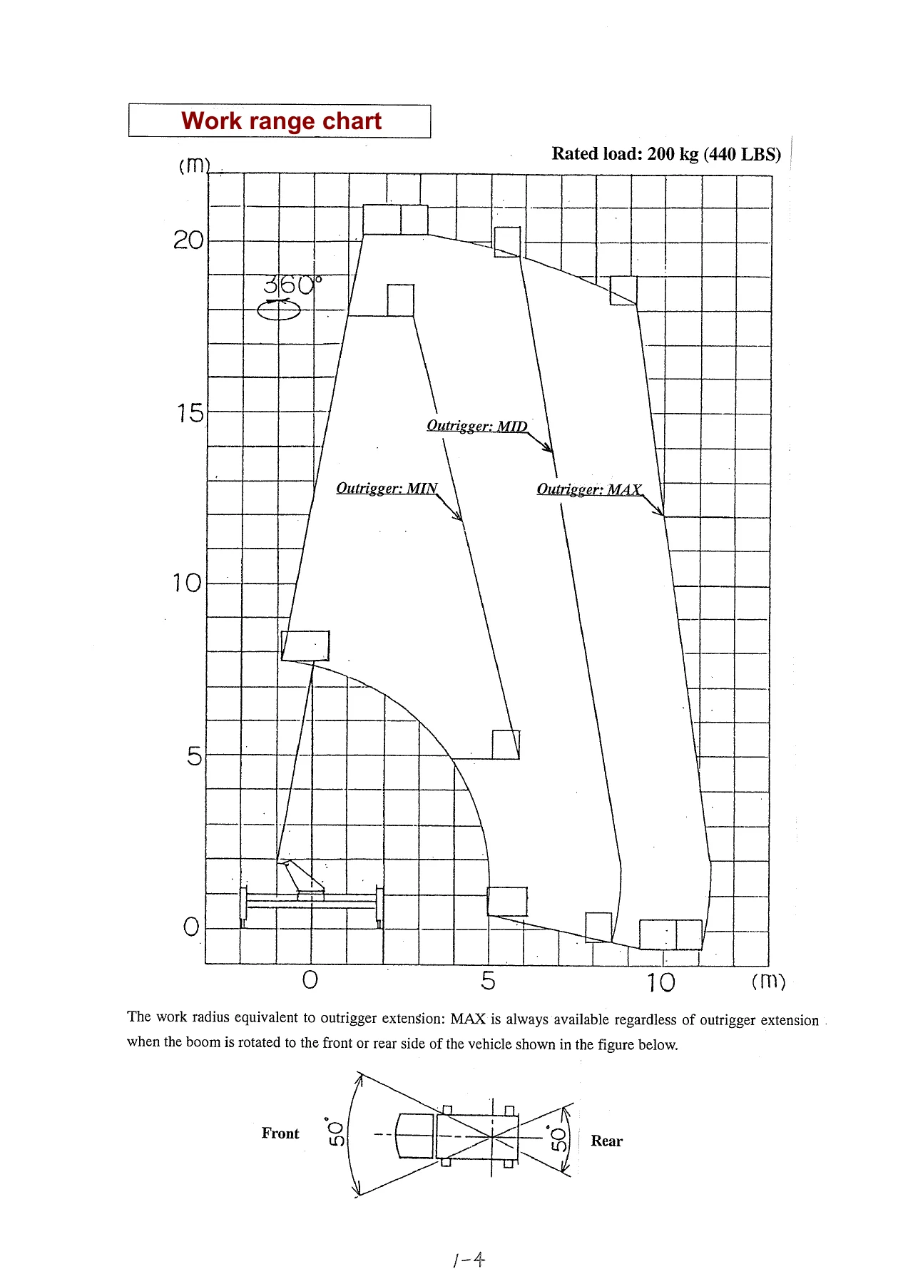
- Rated Load: 200 kg (440 LBS)
Chapters Covered
- 1. General Information — Overall dimensions, specifications, work range chart
- 2. Electric Section
- Main power box (329-02785C, 329-03498F, 329-03499F)
- Engine control board (325-02843, 329-03500)
- Surge killer board (321-03346)
- Main control box
- Valve control board — specifications, input/output characteristics, LED and trimmer functions
- Relay board
- Voice alarm board
- Lower control box (standard and optional Auto rotation stop switch)
- Upper control box (standard and optional Auto rotation stop switch)
- Joystick controller
- Rear control panel
- Work range control system — functions, unit checker, troubleshooting
- Outrigger control box — inputs/outputs, external view, electric schematic, troubleshooting
- Boom angle sensor
- Boom length sensor (K21-W2001, K21-W2003C)
- Rotation sensor
- Outrigger sensor
- Interlock system
- Accelerator motor
- Automatic rotation stop system (Option)
- 3. Electric Circuit for Individual System
- Engine start and stop system (multiple chassis configurations)
- Boom rotation system (with and without automatic rotation stop)
- Boom telescoping system
- Boom elevation system
- Platform rotation system
- Emergency stop system
- Accelerator system
- Interlock system
- Emergency pump and work light system
- Voice alarm system
- Winch system (Option)
- 4. Inspection and Adjustment
- Inspection procedures of work range control system
- Inspection of outrigger extension indicator
- Inspection of work radius
- Inspection of boom rotation limit angle
- Work range control system inspection sheet
- Adjustment of work range control unit
- Inspection and adjustment of actuating speed
- Normal speed adjustment — null trimmer, gain trimmer, TR trimmer, delay trimmer
- Limited speed inspection and adjustment
- Adjustment data sheet
- 5. Appendix
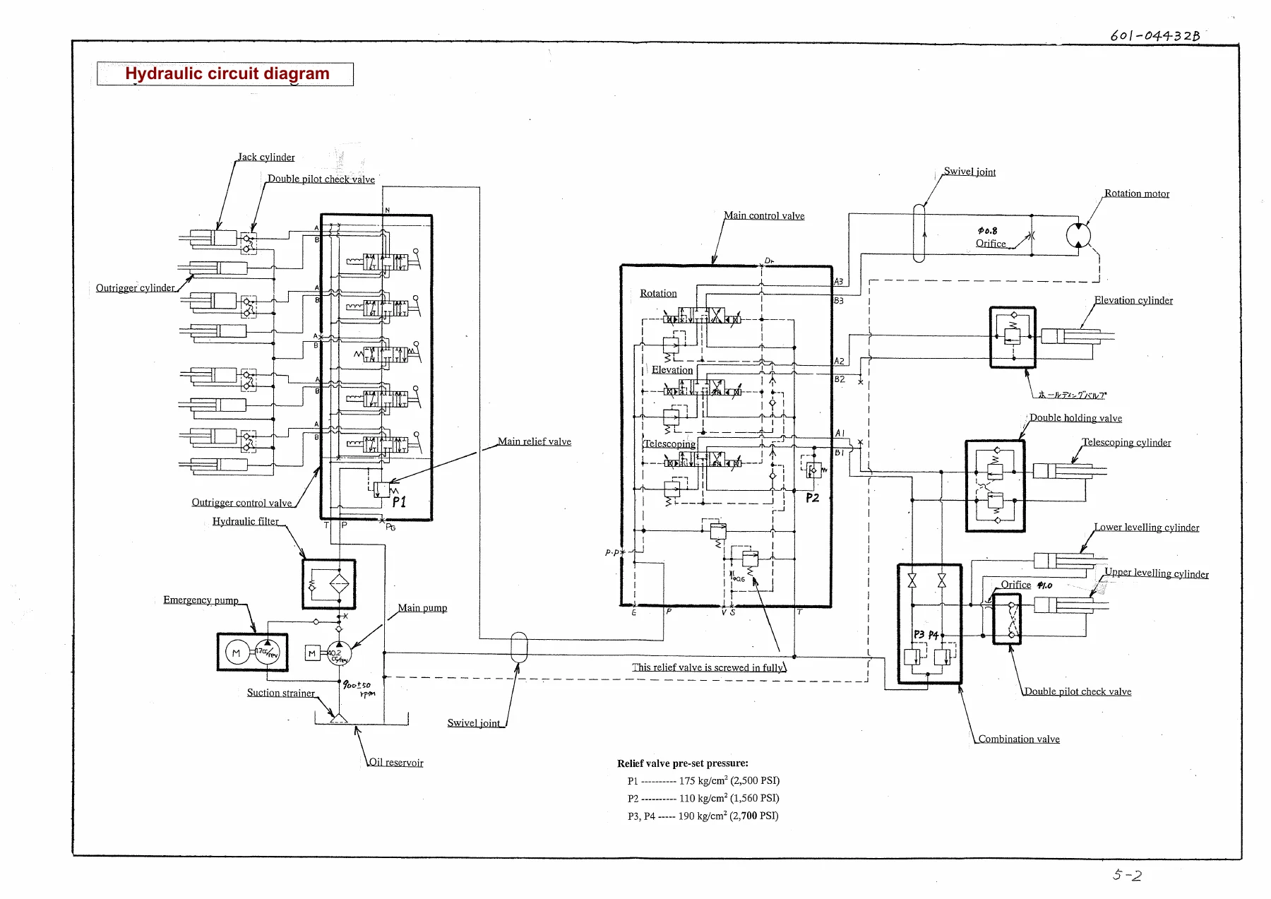
- Hydraulic circuit diagram
- Electrical circuit diagram (602-05234)
- Electrical circuit diagram (602-06401B)
- 6. Inspection Manual
- Procedures of daily inspection
- Daily inspection check sheet
- Procedures of periodical inspection
- Withstand voltage tests
- Function tests
- Periodical inspection check sheet
- Withstand voltage test check sheet
- Function tests check sheet
- Major alteration and repair
The Aichi SK200 service manual gives technicians and maintenance crews a complete reference for the SK200 aerial lift’s electrical and hydraulic systems. It includes board-level component identification for the main power box, engine control board, valve control board, relay board, and voice alarm board — complete with connector pinouts, LED function tables, and trimmer adjustment specifications. The work range control system section details the unit checker, error codes, and troubleshooting procedures for the outrigger control box, boom angle sensor, boom length sensor, and rotation sensor. Hydraulic circuit diagrams show the main control valve, outrigger control valve, jack cylinders, elevation cylinder, telescoping cylinder, and rotation motor with relief valve pre-set pressures. The inspection and adjustment chapter provides specific voltage values, resistance readings, and speed measurements for calibrating the boom angle sensor, boom length sensor, null trimmer, gain trimmer, TR trimmer, and delay trimmer, along with step-by-step procedures for verifying work radius, boom rotation limit angle, and outrigger extension indicators.
What This Manual Enables You to Do
With this Aichi SK200 service manual on hand, you can properly diagnose electrical faults in the main power box, engine control board, valve control board, and relay board using the included schematics and pinout data. You can calibrate the work range control unit, adjust the boom angle and boom length sensors to exact voltage and resistance values, and tune the actuating speeds for rotation, telescoping, and elevation to factory specifications. The manual also supports scheduled maintenance — daily and periodical inspection check sheets, withstand voltage test procedures, function tests, and service limits for natural descent of jack cylinders, elevation cylinder, and telescoping cylinder are all included. Whether you are troubleshooting an outrigger sensor fault, replacing a relay, adjusting the limited speed trimmers, or performing a full annual inspection, the SME-318A manual provides the correct procedures and specifications to complete the job accurately.
Why Correct Procedures and Specifications Matter
The Aichi SK200 is a truck mounted aerial lift with a rated load of 200 kg (440 LBS). Incorrect adjustment of the work range control system, boom angle sensor, or boom length sensor can lead to unsafe operating conditions, improper work radius limiting, or failure of the interlock and emergency stop systems. The service manual provides the exact voltage values, resistance readings, speed measurements, and relief valve pressures needed to keep the machine within its designed safety envelope. Following the manufacturer’s adjustment and inspection procedures helps ensure the aerial lift operates reliably and safely.
IMAGES PREVIEW
Instant PDF Delivery
This Aichi SK200 Truck Mounted Aerial Lift Service Manual is delivered as an instant PDF download — no shipping, no waiting. The file is printable and can be viewed on any device, making it easy to bring the relevant pages directly to the machine during maintenance or repair work. Whether you are a fleet maintenance technician, an independent repair shop, or an owner-operator, the SME-318A manual is an essential reference for keeping your SK200 aerial lift in proper working order.
Reviews
There are no reviews yet.