★ TRUSTED BY 321,897+ PROFESSIONALS WORLDWIDE
🏢
Trusted Business
Verified & Licensed
🛡️
Virus Free Files
100% Safe Downloads
🔒
Secure Payment
SSL Protected
Instant Delivery
Available Immediately
Sale!

Airbus A318/A319/A320/A321 Maintenance Manual – Chapter 25 Equipment & Furnishings – AES Rev 40 (2012) PDF

Original price was: $49.95.Current price is: $29.95.

Comprehensive Airbus A318/A319/A320/A321 maintenance manual for Chapter 25, covering all equipment and furnishings. Essential for technicians and engineers on the A320 family. Instant PDF download.

Instant PDF Download
Available immediately
💾
Save to Your Device
Download & keep forever
🛡️
Antivirus Scanned
100% virus-free
🌍
Trusted Worldwide
175,000+ customers

Description

File Details

  • Manual Type: Official Airbus Aircraft Maintenance Manual (AMM)
  • Brand: Airbus
  • Models Covered: A318, A319, A320, A321
  • Language: English
  • Page Count: 1,851 pages
  • File Format: PDF
  • Document Number: AES
  • Revision: 40
  • Date: May 01, 2012

Chapters Covered

This is the complete Chapter 25 of the official Airbus AMM for the A320 family, covering Equipment and Furnishings. The manual is structured into tasks for description, operation, removal, installation, adjustment, inspection, and repair. Key chapters include:

IMAGES PREVIEW

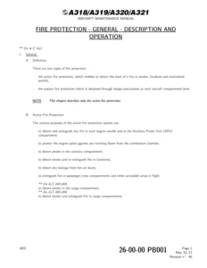
Airbus A318/A319/A320/A321 Maintenance Manual - Chapter 25 Equipment & Furnishings - AES Rev 40 (2012) PDF — PDF page 1 preview
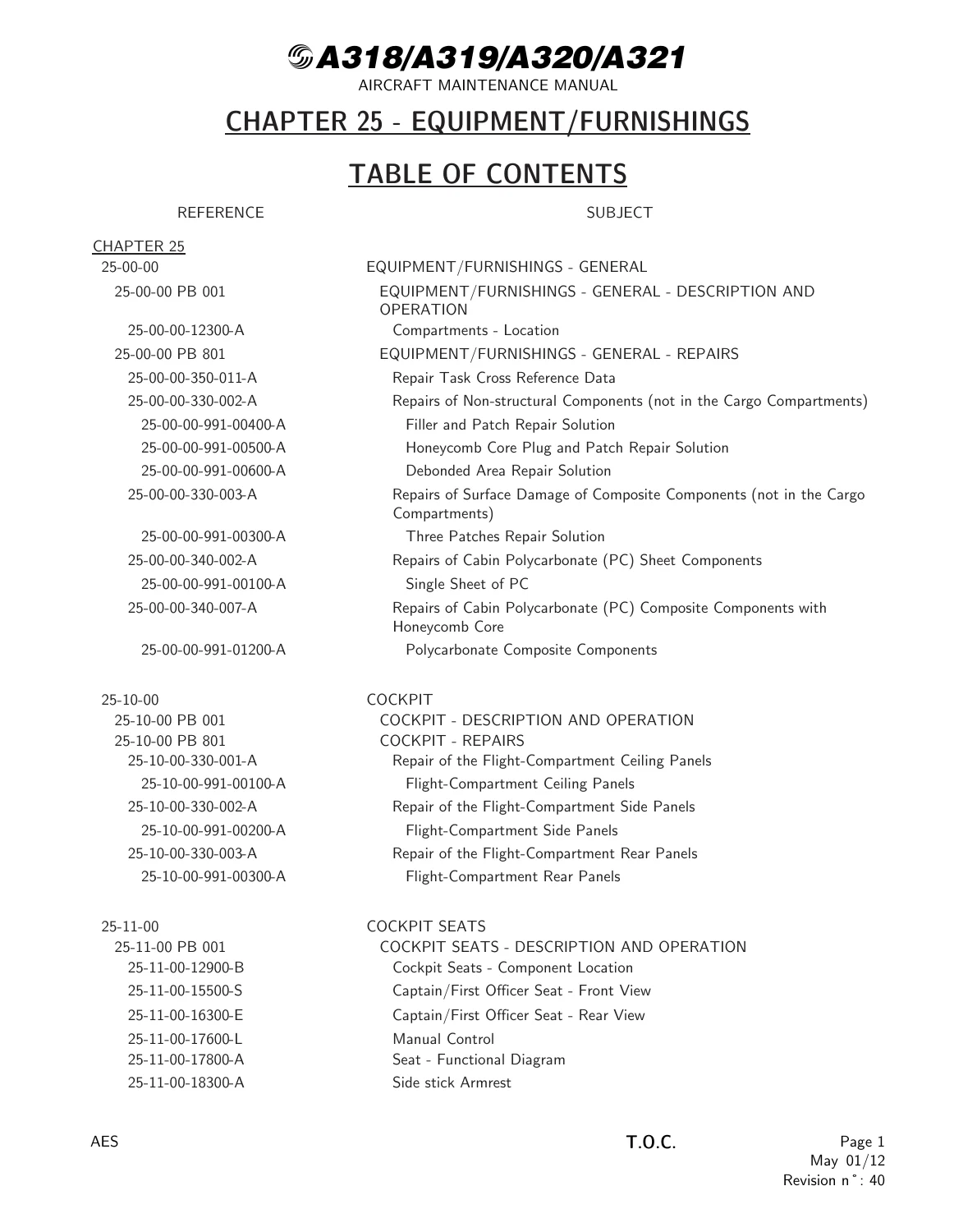
Airbus A318/A319/A320/A321 Maintenance Manual - Chapter 25 Equipment & Furnishings - AES Rev 40 (2012) PDF — PDF page 35 preview
Airbus A318/A319/A320/A321 Maintenance Manual - Chapter 25 Equipment & Furnishings - AES Rev 40 (2012) PDF — PDF page 73 preview

  • 25-00-00 Equipment/Furnishings – General: General description, component locations, and general repair tasks for non-structural components, surface damage, and polycarbonate components.
  • 25-10-00 Cockpit: Description and repair of cockpit ceiling, side, and rear panels.
  • 25-11-00 Cockpit Seats: Complete details on captain, first officer, third, and fourth occupant seats. Covers deactivation/reactivation, adjustment, inspection, and removal/installation of components like cushions, shrouds, safety harnesses, armrests, and lumbar rests.
  • 25-13-00 Lining and Furnishings: Covers cockpit carpet, foot rests, sliding tables, sunvisors, window roller-blinds, and foam panels. Includes cleaning and painting instructions.
  • 25-20-00 Passenger Compartment: Detailed system descriptions, component locations, and comprehensive repair and refurbishment tasks for overhead stowage bins, sidewall panels, ceiling panels, floor coverings, and decor foil.
  • 25-21-00 Passenger Compartment Seats: Covers all passenger seats, including installation, inspection, seat-to-floor attachments, and seat belts. Also details the In-Seat Power-Supply System (PED power supply).
  • 25-22-00 Cabin Attendant Seats: Information on free-standing, wall-mounted, and swivel cabin attendant seats, including restraint systems and inspection/check procedures.
  • 25-23-00 Linings and Furnishings: Comprehensive guide to ceiling, sidewall, door, and door frame linings for both the passenger cabin and utility areas.
  • 25-24-00 Overhead Stowage Compartments: Complete details on the design, adjustment, and removal/installation of all overhead stowage bins and components.
  • 25-25-00 Passenger Service Information Units (PSIU): Covers the PSU components, including passenger service/information units, reading lights, fresh air outlets, and filler panels.
  • 25-26-00 Curtains and Partitions: Details on the removal/installation of cabin curtains, curtain rails, and partitions, including class dividers.
  • 25-27-00 Ancillary Equipment: Information on stowages, emergency equipment stowage, and doghouses.
  • 25-28-00 Floor Covering: Covers the installation, removal, and repair of both textile and non-textile floor coverings (carpet, NTF) and moisture barrier foil (Mylar).
  • 25-29-00 Electrical Service Supply: Description and operational test of the electrical service supply system for vacuum cleaners and other sockets.
  • 25-30-00 Buffet and Galley: General description, servicing, inspection, and repair of buffet and galley units and their equipment.
  • 25-31-00 Forward Galley & 25-33-00 Aft Galley: Complete removal/installation procedures for forward and aft galley units, including all electrical, water, and air connections.
  • 25-35-00 Galley Equipment: Covers the maintenance, deactivation, adjustment, and removal/installation of specific galley equipment like coffee makers, ovens, and control panels.
  • 25-40-00 Lavatories: A full section on lavatory description, operation, maintenance, inspection, and repair, including door adjustments, shim procedures, and repairs to the washbasin, floor pan, and toilet shroud.
  • 25-41-00 Forward Lavatories, 25-43-00 Aft Lavatories: Detailed removal and installation procedures for forward and aft lavatory units (Lavatory A, D, and E).
  • 25-44-00 Razor Supply: Description and operational test of the razor supply system and static inverter.
  • 25-45-00 Lavatory Equipment: Covers the removal/installation of all individual lavatory components like the mirror, soap dispenser, waste chute flap, ash tray, waste box, access door, lavatory door, lock, toilet shroud, hand grip, seat cover dispenser, baby nursing table, lining, and door microswitch.
  • 25-50-00 Cargo Compartments: Broad description and detailed inspection, cleaning, painting, and repair tasks for the cargo compartments, linings, nets, and attachment points.
  • 25-52-00 Cargo Loading/Restraint: Description and component location of the semi-automatic cargo loading system.
  • 25-54-00 Linings and Furnishings/Forward Cargo Compartment & 25-55-00 Linings and Furnishings/Aft Cargo Compartment: Specific removal/installation and repair procedures for linings, partitions, stanchions, and tie-down fittings in the forward and aft cargo compartments.
  • 25-60-00 Emergency: Overview of emergency equipment. Includes escape facilities for cockpit and cabin.
  • 25-62-00 Escape Facilities – Cabin: Extensive details on escape slide/rafts, offwing escape slides, their release mechanisms, and inflation reservoirs. Includes maintenance practices, adjustment, servicing, deactivation, and inspection.
  • 25-63-00 Evacuation Signaling Equipment: Description and operational test of the evacuation signaling system.
  • 25-65-00 Miscellaneous Emergency Equipment: Covers safety barrier straps, megaphones, and cockpit flashlights. Includes maintenance and installation procedures.
  • 25-66-00 Floatation and Survival Equipment: Description and inspection of life vests, survival kits, and life lines.
  • 25-68-00 Rapid Decompression Safety System: Description of the system and detailed removal/installation procedures for decompression panels.
  • 25-70-00 Accessory Compartments: General description and component locations of the avionics and equipment compartments.
  • 25-71-00 Avionics Compartment: Detailed description of the avionics compartment layout and borescope inspection procedures for the 80VU rack.
  • 25-80-00 Insulation (Thermal and Acoustical): Description and comprehensive maintenance, inspection, and repair procedures for the aircraft’s thermal and acoustical insulation blankets.

Complete PDF Bookmark Tree

Complete Bookmarks

The complete bookmarks in the “Airbus A318/A319/A320/A321 Maintenance Manual – Chapter 25 Equipment & Furnishings – AES Rev 40 (2012) PDF” are as follows:

Manual Front Matter
Chapter 05 – TIME LIMITS – MAINTENANCE CHECKS
Chapter 06 – DIMENSIONS AND AREAS
Chapter 07 – LIFTING AND SHORING
Chapter 08 – LEVELING AND WEIGHING
Chapter 09 – TOWING AND TAXIING
Chapter 10 – PARKING, MOORING, STORAGE & RETURN TO SERVICE
Chapter 11 – PLACARDS AND MARKINGS
Chapter 12 – SERVICING
Chapter 20 – STANDARD PRACTICES – AIRFRAME
Chapter 21 – AIR CONDITIONING
Chapter 22 – AUTO FLIGHT
Chapter 23 – COMMUNICATIONS
Chapter 24 – ELECTRICAL POWER
Chapter 25 – EQUIPMENT/FURNISHINGSp. 1
Table of Contentsp. 1
25-00 – EQUIPMENT/FURNISHINGS – GENERALp. 34
25-00-00 – EQUIPMENT/FURNISHINGS – GENERALp. 34
25-00-00 PB 001 CONF 00 – EQUIPMENT/FURNISHINGS – GENERAL – DESCRIPTION AND OPERATIONp. 34
Generalp. 34
Component Locationp. 35
System Descriptionp. 36
Figure 25-00-00-12300-A – Compartments – Locationp. 37
25-00-00 PB 801 CONF 00 – EQUIPMENT/FURNISHINGS – GENERAL – REPAIRSp. 38
25-00-00-350-011-A – Repair Task Cross Reference Datap. 38
25-00-00-330-002-A – Repairs of Non-structural Components (not in the Cargo Compartments)p. 40
Figure 25-00-00-991-00400-A – Filler and Patch Repair Solutionp. 44
Figure 25-00-00-991-00500-A – Honeycomb Core Plug and Patch Repair Solutionp. 45
Figure 25-00-00-991-00600-A – Debonded Area Repair Solutionp. 46
25-00-00-330-003-A – Repairs of Surface Damage of Composite Components (not in the Cargo Compartments)p. 47
Figure 25-00-00-991-00300-A – Three Patches Repair Solutionp. 50
25-00-00-340-002-A – Repairs of Cabin Polycarbonate (PC) Sheet Componentsp. 51
Figure 25-00-00-991-00100-A – Single Sheet of PCp. 54
25-00-00-340-007-A – Repairs of Cabin Polycarbonate (PC) Composite Components with Honeycomb Corep. 55
Figure 25-00-00-991-01200-A – Polycarbonate Composite Componentsp. 59
25-10 – COCKPITp. 60
25-10-00 – COCKPITp. 60
25-10-00 PB 001 CONF 00 – COCKPIT – DESCRIPTION AND OPERATIONp. 60
General Descriptionp. 60
25-10-00 PB 801 CONF 00 – COCKPIT – REPAIRSp. 61
25-10-00-330-001-A – Repair of the Flight-Compartment Ceiling Panelsp. 61
Figure 25-10-00-991-00100-A – Flight-Compartment Ceiling Panelsp. 63
25-10-00-330-002-A – Repair of the Flight-Compartment Side Panelsp. 64
Figure 25-10-00-991-00200-A – Flight-Compartment Side Panelsp. 66
25-10-00-330-003-A – Repair of the Flight-Compartment Rear Panelsp. 67
Figure 25-10-00-991-00300-A – Flight-Compartment Rear Panelsp. 69
25-11 – COCKPIT SEATSp. 70
25-11-00 – COCKPIT SEATSp. 70
25-11-00 PB 001 CONF 00 – COCKPIT SEATS – DESCRIPTION AND OPERATIONp. 70
Generalp. 70
Component Locationp. 71
Component Descriptionp. 72
Operation/Control and Indicatingp. 74
Figure 25-11-00-12900-B – Cockpit Seats – Component Locationp. 77
Figure 25-11-00-15500-S – Captain/First Officer Seat – Front Viewp. 78
Figure 25-11-00-16300-E – Captain/First Officer Seat – Rear Viewp. 79
Figure 25-11-00-17600-L – Manual Controlp. 80
Figure 25-11-00-17800-A – Seat – Functional Diagramp. 81
Figure 25-11-00-18300-A – Side stick Armrestp. 82
Figure 25-11-00-18500-B – Safety Harnessp. 83
Figure 25-11-00-18600-B – Third Occupant Seatp. 84
Figure 25-11-00-19200-F – Stowage and Deployment of the Third Occupant Seatp. 85
Figure 25-11-00-19400-B – Safety Harness.p. 86
Figure 25-11-00-19800-B – Fourth Occupant Seatp. 87
25-11-00 PB 401 CONF 00 – COCKPIT SEATS – DEACTIVATION/REACTIVATIONp. 88
25-11-00-040-001-A – Deactivation of the Defective Recline System of the CAPT (F/O) Seatp. 88
Figure 25-11-00-991-00200-A – Defective Recline System of the CAPT (F/O) Seatp. 90
25-11-00-440-001-A – Reactivation of the Defective Recline System of the CAPT (F/O) Seatp. 91
25-11-00-040-002-A – Deactivation of the Inoperative Adjustment System of the CAPT (F/O) Seat (Electrical Control)p. 92
25-11-00-440-002-A – Reactivation of the Inoperative Adjustment System of the CAPT (F/O) Seat (Electrical Control)p. 94
25-11-00-040-003-A – Deactivation of the Third Occupant Seatp. 95
25-11-00-440-003-A – Reactivation of the Third Occupant Seatp. 97
25-11-00-040-004-A – Deactivation of the Fourth Occupant Seatp. 99
25-11-00-440-004-A – Reactivation of the Fourth Occupant Seatp. 101
25-11-00 PB 501 CONF 00 – COCKPIT SEATS – ADJUSTMENT/TESTp. 103
25-11-00-710-001-A – Operational Test of the Captain and First Officer Seatsp. 103
25-11-00 PB 601 CONF 00 – COCKPIT SEATS – INSPECTION/CHECKp. 106
25-11-00-200-001-A – Inspection/Check of the Cockpit Seatsp. 106
25-11-00-200-002-A – Inspection/Check of the Shoulder Harness and Seat Beltp. 107
25-11-41 – SEAT – THIRD OCCUPANTp. 109
25-11-41 PB 401 CONF 00 – SEAT – THIRD OCCUPANT – REMOVAL/INSTALLATIONp. 109
25-11-41-000-001-A – Removal of the Third Occupant Seatp. 109
Figure 25-11-41-991-00100-A – Third Occupant Seatp. 110
25-11-41-400-001-A – Installation of the Third Occupant Seatp. 111
25-11-41 PB 601 CONF 00 – SEAT – THIRD OCCUPANT – INSPECTION/CHECKp. 113
25-11-41-200-001-A – Inspection/Check of the Third Occupant Seatp. 113
25-11-42 – SEAT – FOURTH OCCUPANTp. 114
25-11-42 PB 401 CONF 00 – SEAT – FOURTH OCCUPANT – REMOVAL/INSTALLATIONp. 114
25-11-42-000-001-A – Removal of the Fourth Occupant Seatp. 114
Figure 25-11-42-991-00100-B – Fourth Occupant Seatp. 115
25-11-42-400-001-A – Installation of the Fourth Occupant Seatp. 117
25-11-42 PB 601 CONF 00 – SEAT – FOURTH OCCUPANT – INSPECTION/CHECKp. 118
25-11-42-200-001-A – Inspection/Check of the Fourth Occupant Seatp. 118
25-11-51 – SEAT – CAPTAIN/FIRST OFFICERp. 119
25-11-51 PB 401 CONF 00 – SEAT – CAPTAIN/FIRST OFFICER – REMOVAL/INSTALLATIONp. 119
25-11-51-000-001-A – Removal of the Captain/First Officer Seatp. 119
Figure 25-11-51-991-00100-E – Captain Seatp. 121
Figure 25-11-51-991-00200-E – First Officer Seatp. 122
25-11-51-400-001-A – Installation of the Captain/First Officer Seatp. 123
25-11-51 PB 601 CONF 00 – SEAT – CAPTAIN/FIRST OFFICER – INSPECTION/CHECKp. 126
25-11-51-200-001-A – Inspection/Check of the Captain/First Officer Seatp. 126
25-11-51-200-002-A – Check of Adjustment of Seat Control Cablesp. 127
Figure 25-11-51-991-00300-A – Installation of Adjustment Toolp. 130
25-11-61 – CUSHIONS – SEAT,CAPTAIN/FIRST OFFICERp. 131
25-11-61 PB 401 CONF 00 – CUSHIONS – SEAT,CAPTAIN/FIRST OFFICER – REMOVAL/INSTALLATIONp. 131
25-11-61-000-001-A – Removal of the Captain (First Officer) Seat Cushionp. 131
Figure 25-11-61-991-00100-A – Captain (First Officer) Seat Cushionp. 132
25-11-61-400-001-A – Installation of the Captain (First Officer) Seat Cushionp. 133
25-11-62 – SHROUD ASSY – SEAT,CAPTAIN/FIRST OFFICERp. 134
25-11-62 PB 401 CONF 00 – SHROUD ASSY – SEAT,CAPTAIN/FIRST OFFICER – REMOVAL/INSTALLATIONp. 134
25-11-62-000-001-A – Removal of the Captain (First Officer) Seat Shroud Assyp. 134
Figure 25-11-62-991-00100-B – Captain (First Officer) Seat Shroud Assyp. 136
25-11-62-400-001-A – Installation of the Captain (First Officer) Seat Shroud Assyp. 137
25-11-63 – SAFETY HARNESS – SEAT, CAPTAIN/ FIRST OFFICERp. 139
25-11-63 PB 401 CONF 00 – SAFETY HARNESS – SEAT, CAPTAIN/ FIRST OFFICER – REMOVAL/INSTALLATIONp. 139
25-11-63-000-001-A – Removal of the Captain (First Officer) Seat Harness Assyp. 139
Figure 25-11-63-991-00100-G – Safety Harnessp. 141
25-11-63-400-001-A – Installation of the Captain (First Officer) Seat Harness Assyp. 143
25-11-64 – HEADREST – SEAT, CAPTAIN/FIRST OFFICERp. 146
25-11-64 PB 401 CONF 00 – HEADREST – SEAT, CAPTAIN/FIRST OFFICER – REMOVAL/INSTALLATIONp. 146
25-11-64-000-001-A – Removal of the Captain (First Officer) Seat-Headrest Assyp. 146
Figure 25-11-64-991-00100-A – Captain (First Officer) Seat-Headrest Assyp. 147
25-11-64-400-001-A – Installation of the Captain (First Officer) Seat-Headrest Assyp. 148
25-11-65 – ARMREST ASSY – SEAT, CAPTAIN/FIRST OFFICERp. 150
25-11-65 PB 401 CONF 00 – ARMREST ASSY – SEAT, CAPTAIN/FIRST OFFICER – REMOVAL/INSTALLATIONp. 150
25-11-65-000-001-A – Removal of the Captain (First Officer) Seat Armrest Assyp. 150
Figure 25-11-65-991-00100-A – Captain (First Officer) Seat Armrest Assyp. 152
25-11-65-400-001-A – Installation of the Captain (First Officer) Seat Armrest Assyp. 154
Figure 25-11-65-991-00200-A – Adjustment of the Captain (First Officer) Seat Armrest Assyp. 157
25-11-65 PB 501 CONF 00 – ARMREST ASSY – SEAT, CAPTAIN/FIRST OFFICER – ADJUSTMENT/TESTp. 158
25-11-65-710-001-A – Operational Test of the Captain (First Officer) Seat Inboard Armrest-Assyp. 158
25-11-66 – ARMREST ASSY – ASSIST, CAPTAIN/ FIRST OFFICER SEATp. 160
25-11-66 PB 401 CONF 00 – ARMREST ASSY – ASSIST, CAPTAIN/ FIRST OFFICER SEAT – REMOVAL/INSTALLATIONp. 160
25-11-66-000-001-A – Removal of the Captain (First Officer) Seat Assist Armrest-Assyp. 160
Figure 25-11-66-991-00100-A – Captain (First Officer) Seat Assist Armrest Assyp. 162
25-11-66-400-001-A – Installation of the Captain (First Officer) Seat Assist Armrest-Assyp. 163
25-11-66 PB 501 CONF 00 – ARMREST ASSY – ASSIST, CAPTAIN/ FIRST OFFICER SEAT – ADJUSTMENT/TESTp. 165
25-11-66-710-001-A – Operational Test of the Captain (First Officer) Seat Side Stick Armrest-Assyp. 165
25-11-67 – LUMBAR REST ASSY – SEAT, CAPTAIN/ FIRST OFFICERp. 167
25-11-67 PB 401 CONF 00 – LUMBAR REST ASSY – SEAT, CAPTAIN/ FIRST OFFICER – REMOVAL/INSTALLATIONp. 167
25-11-67-000-001-A – Removal of the Captain (First Officer) Seat Lumbar-Restp. 167
Figure 25-11-67-991-00100-A – Captain (First Officer) Seat Lumbar-Restp. 168
25-11-67-400-001-A – Installation of the Captain (First Officer) Seat Lumbar-Restp. 169
25-11-68 – CYLINDER ASSY – SEAT CAPTAIN/FIRST OFFICERp. 171
25-11-68 PB 401 CONF 00 – CYLINDER ASSY – SEAT CAPTAIN/FIRST OFFICER – REMOVAL/INSTALLATIONp. 171
25-11-68-000-001-A – Removal of the Captain (First Officer) Seat Cylinder Assyp. 171
Figure 25-11-68-991-00100-A – Captain (First Officer) Seat Cylinder Assyp. 173
25-11-68-400-001-A – Installation of the Captain (First Officer) Seat Cylinder Assyp. 174
25-11-69 – ACCESSORIES – CAPTAIN/FIRST OFFICER SEAT PAN AND BASEp. 176
25-11-69 PB 401 CONF 00 – ACCESSORIES – CAPTAIN/FIRST OFFICER SEAT PAN AND BASE – REMOVAL/INSTALLATIONp. 176
25-11-69-000-001-A – Removal of the Captain (First Officer) Seat Pan and Base Accessoriesp. 176
Figure 25-11-69-991-00100-A – Captain (First Officer) Seat Pan and Base Accessoriesp. 178
25-11-69-400-001-A – Installation of the Captain (First Officer) Seat Pan and Base Accessoriesp. 179
25-13 – LINING AND FURNISHINGSp. 182
25-13-00 – LINING AND FURNISHINGSp. 182
25-13-00 PB 001 CONF 00 – LINING AND FURNISHINGS – DESCRIPTION AND OPERATIONp. 182
Generalp. 182
Descriptionp. 183
Figure 25-13-00-11200-A – Cockpit Lining and Furnishingsp. 184
Figure 25-13-00-13000-A – Cockpit Carpet Installationp. 185
25-13-00 PB 401 CONF 00 – LINING AND FURNISHINGS – DEACTIVATION/REACTIVATIONp. 186
25-13-00-040-001-A – Deactivation of the Captain and/or First Officer Sliding-Tablesp. 186
25-13-00-440-001-A – Reactivation of the Captain and/or First Officer Sliding-Tablesp. 187
25-13-00-040-002-A – Deactivation of the Captain and/or First Officer Retractable Foot-Restsp. 188
25-13-00-440-002-A – Reactivation of the Captain and/or First Officer Retractable Foot-Restsp. 189
25-13-00 PB 701 CONF 00 – LINING AND FURNISHINGS – CLEANING/PAINTINGp. 190
25-13-00-100-001-A – Cleaning of Foam Plastic (Polyurethane) Partsp. 190
25-13-00-370-001-A – Painting of the Internal Cockpit Surfacesp. 192
25-13-11 – SUNVISOR – WINDSHIELDp. 194
25-13-11 PB 401 CONF 00 – SUNVISOR – WINDSHIELD – REMOVAL/INSTALLATIONp. 194
25-13-11-000-001-A – Removal of the Windshield Sunvisorp. 194
Figure 25-13-11-991-00100-B – Windshield Sunvisorp. 195
25-13-11-400-001-A – Installation of the Windshield Sunvisorp. 196
25-13-14 – FOOT REST AND SLIDING TABLE ASSEMBLYp. 197
25-13-14 PB 201 CONF 00 – FOOT REST AND SLIDING TABLE ASSEMBLY – MAINTENANCE PRACTICESp. 197
25-13-14-820-001-A – Adjustment of the Cockpit Tablep. 197
Figure 25-13-14-991-01000-A – Adjustment of the Cockpit Tablep. 199
25-13-14 PB 401 CONF 00 – FOOT REST AND SLIDING TABLE ASSEMBLY – REMOVAL/INSTALLATIONp. 201
25-13-14-000-001-A – Removal of the Foot Rest and Sliding Table Assemblyp. 201
Figure 25-13-14-991-00100-A – Foot Rest and Sliding Table Assembly.p. 202
25-13-14-400-001-A – Installation of the Foot Rest and Sliding Table Assemblyp. 203
25-13-14-000-002-A – Removal of the Sliding Tablep. 204
Figure 25-13-14-991-00200-A – Sliding Table.p. 205
25-13-14-400-002-A – Installation of the Sliding Tablep. 206
25-13-14-000-003-A – Removal of the Actuator on the Foot Rest Assemblyp. 207
Figure 25-13-14-991-00300-C – Actuator on the Foot Rest and Sliding Table Assemblyp. 209
25-13-14-400-003-A – Installation of the Actuator on the Foot Rest Assemblyp. 210
25-13-14-000-005-A – Removal of the Captain and First-Officer Retractable Foot-Restsp. 212
Figure 25-13-14-991-00900-B – Captain and First-Officer Retractable Foot-Restsp. 213
25-13-14-400-005-A – Installation of the Captain and First-Officer Retractable Foot-Restsp. 214
25-13-14 PB 601 CONF 00 – FOOT REST AND SLIDING TABLE ASSEMBLY – INSPECTION/CHECKp. 216
25-13-14-200-002-A – Visual Inspection of the Foot Rest Actuatorp. 216
Figure 25-13-14-991-00600-A – Visual Inspection of the Foot Rest Actuatorp. 218
25-13-41 – LINING PANELSp. 219
25-13-41 PB 401 CONF 00 – LINING PANELS – REMOVAL/INSTALLATIONp. 219
25-13-41-000-001-A – Removal of the Ceiling Panelsp. 219
Figure 25-13-41-991-00100-A – Ceiling Panelsp. 221
25-13-41-400-001-A – Installation of the Ceiling Panelsp. 222
25-13-41-000-002-A – Removal of the Sidewall Panelsp. 224
Figure 25-13-41-991-00200-A – Sidewall Panels (211EW, 212EW, 211FW, 212FW, 211DW, 212DW)p. 226
Figure 25-13-41-991-00300-A – Sidewall Panels (211AW, 212AW, 211BW, 212BW)p. 227
Figure 25-13-41-991-00400-A – Sidewall Panel 211LWp. 228
Figure 25-13-41-991-00500-A – Sidewall Panels (212HW, 212JW)p. 229
Figure 25-13-41-991-00600-A – Sidewall Panel 212KWp. 230
25-13-41-400-002-A – Installation of the Sidewall Panelsp. 231
25-13-42 – ROLLER BLIND – SLIDING WINDOWp. 234
25-13-42 PB 401 CONF 00 – ROLLER BLIND – SLIDING WINDOW – REMOVAL/INSTALLATIONp. 234
25-13-42-000-001-A – Removal of the Sliding Window Roller-Blindp. 234
Figure 25-13-42-991-00100-A – Sliding Window Roller-Blindp. 235
25-13-42-400-001-A – Installation of the Sliding Window Roller-Blindp. 236
25-13-43 – ROLLER BLIND – FIXED WINDOWp. 237
25-13-43 PB 401 CONF 00 – ROLLER BLIND – FIXED WINDOW – REMOVAL/INSTALLATIONp. 237
25-13-43-000-001-A – Removal of the Fixed Window Roller-Blindp. 237
Figure 25-13-43-991-00100-A – Fixed Window Roller-Blindp. 238
25-13-43-400-001-A – Installation of the Fixed Window Roller-Blindp. 239
25-13-44 – CARPET – COCKPITp. 240
25-13-44 PB 401 CONF 00 – CARPET – COCKPIT – REMOVAL/INSTALLATIONp. 240
25-13-44-000-001-A – Removal of the Cockpit Textile Floor Covering (Carpet)p. 240
Figure 25-13-44-991-00200-A – Case Stopsp. 242
Figure 25-13-44-991-00100-A – Textile Floor Coveringp. 243
25-13-44-400-001-A – Installation of the Cockpit Textile Floor Covering (Carpet)p. 244
25-13-45 – COCKPIT CENTER PEDESTAL FOAM PANELSp. 247
25-13-45 PB 401 CONF 00 – COCKPIT CENTER PEDESTAL FOAM PANELS – REMOVAL/INSTALLATIONp. 247
25-13-45-000-001-A – Removal of the Foam Panelsp. 247
Figure 25-13-45-991-00100-A – Left Foam Panelp. 249
Figure 25-13-45-991-00200-A – Right Foam Panelp. 250
25-13-45-400-001-A – Installation of the Foam Panelsp. 251
25-13-46 – COAT STOWAGEp. 254
25-13-46 PB 401 CONF 00 – COAT STOWAGE – REMOVAL/INSTALLATIONp. 254
25-13-46-000-001-A – Removal of the Coat Stowagep. 254
Figure 25-13-46-991-00100-A – Coat Stowagep. 255
25-13-46-400-001-A – Installation of the Coat Stowagep. 257
25-14 – COCKPIT EQUIPMENT RACKSp. 259
25-14-00 – COCKPIT EQUIPMENT RACKSp. 259
25-14-00 PB 001 CONF 00 – COCKPIT EQUIPMENT RACKS – DESCRIPTION AND OPERATIONp. 259
Generalp. 259
Component Locationp. 260
Descriptionp. 261
Figure 25-14-00-12300-A – Rear Panel 120VU – Component Locationp. 262
Figure 25-14-00-13800-A – Rear Panel 120VUp. 263
25-20 – PASSENGER COMPARTMENTp. 264
25-20-00 – PASSENGER COMPARTMENTp. 264
25-20-00 PB 001 CONF 00 – PASSENGER COMPARTMENT – DESCRIPTION AND OPERATIONp. 264
Generalp. 264
Component Locationp. 265
System Descriptionp. 266
Figure 25-20-00-14000-BI – Cabin Layout VX1p. 267
Figure 25-20-00-14000-IO – Cabin Layout – AES02/VX02 (Aerolineas de Columbia)p. 268
25-20-00 PB 401 CONF 00 – PASSENGER COMPARTMENT – DEACTIVATION/REACTIVATIONp. 269
25-20-00-040-001-A – Deactivation of Overhead Stowage Bin(s)/Cabin and Galley Storage Compartmentp. 269
25-20-00-440-001-A – Reactivation of Overhead Stowage Bin(s)/Cabin and Galley Storage Compartmentp. 271
25-20-00 PB 701 CONF 00 – PASSENGER COMPARTMENT – CLEANING/PAINTINGp. 272
25-20-00-370-001-A – Refurbishment of the Handrail, Interiors and the Doors of the Overhead Stowage Compartmentsp. 272
Figure 25-20-00-991-00100-B – Component Locationp. 278
25-20-00-370-002-A – Refurbishment of the Cabin Sidewall Panel, Cabin Ceiling Panel, Cove Light Panel and the Passenger Service Unit Panelp. 279
25-20-00-370-003-A – Refurbishment of the Lavatory Wall and Lavatory Interior Partsp. 289
25-20-00-370-004-A – Refurbishment of the Exit Ceiling and the Overwing Emergency Exit/Hatch Coverp. 293
25-20-00-370-005-A – Refurbishment of the Partition and the Door/Doorframe Panelp. 298
25-20-00 PB 801 CONF 00 – PASSENGER COMPARTMENT – REPAIRSp. 303
25-20-00-350-001-A – Repair of Insert Nut Attachments in Components with Honeycomb Corep. 303
Figure 25-20-00-991-00200-A – Metal Inserts in Honeycomb Core Panelp. 307
25-20-00-350-003-A – Repair of the Non-Textile Floor Covering (NTF)p. 309
Figure 25-20-00-991-00300-A – Example of Silicone NTF Repairp. 315
Figure 25-20-00-991-00400-A – NTF Informationp. 316
Figure 25-20-00-991-00500-A – Welded Joint Repairp. 318
25-20-00-350-004-A – Repair of the Moisture Barrier Foil (MYLAR)p. 320
25-20-00-350-005-A – Replacement of the Aluminum Profile on the Lower Sidewall-Panelp. 322
Figure 25-20-00-991-00600-A – Aluminum Profilep. 324
25-20-00-340-002-A – Repair of an Overhead Stowage Compartment (OHSC)p. 325
Figure 25-20-00-991-00700-A – Seal – OHSCp. 331
Figure 25-20-00-991-00800-A – Bottom Panel – OHSCp. 332
Figure 25-20-00-991-00900-A – Handrail – OHSCp. 333
Figure 25-20-00-991-01000-A – Handrail Attachment – OHSCp. 334
Figure 25-20-00-991-01100-A – Partition/Stiffener – OHSCp. 335
25-20-00-370-006-A – Repair of the Paint Coat on Componentsp. 336
25-20-00-340-003-A – Repair/Replacement of Decor Foilp. 340
25-20-00-340-004-A – Repair of the Vacuum-Cleaner Outlet Doorp. 345
25-20-00-340-005-A – Repair of Sidewall Linings and Ceiling Panelsp. 347
Figure 25-20-00-991-01200-A – Type 2 Damagep. 354
Figure 25-20-00-991-01300-A – Type 3 Damagep. 355
Figure 25-20-00-991-01400-A – Type 4 Damagep. 356
25-21 – PASSENGER COMPARTMENT SEATSp. 357
25-21-00 – PASSENGER COMPARTMENT SEATSp. 357
25-21-00 PB 001 CONF 00 – PASSENGER COMPARTMENT SEATS – DESCRIPTION AND OPERATIONp. 357
Generalp. 357
Component Locationp. 358
Descriptionp. 359
Power Supplyp. 360
Component Descriptionp. 361
Operation/Control and Indicatingp. 362
Figure 25-21-00-12900-IY – Seat Layout Component Location – AES02/VX02 (Aerolineas de Columbia)p. 363
Figure 25-21-00-13100-E – PED Power Supply – Component Locationp. 364
Figure 25-21-00-15300-BK – Seat Description – Business Class – Examplep. 365
Figure 25-21-00-15400-A – Economy-Class Seats – Examplep. 367
Figure 25-21-00-15400-AV – Seat Description – Tourist Class – Examplep. 373
Figure 25-21-00-17600-D – PED Power Supply – Schematicp. 375
25-21-00 PB 501 CONF 00 – PASSENGER COMPARTMENT SEATS – ADJUSTMENT/TESTp. 377
25-21-00-710-002-A – Operational Test of the In-Seat Power-Supply System (PED Power Supply)p. 377
25-21-00 PB 601 CONF 00 – PASSENGER COMPARTMENT SEATS – INSPECTION/CHECKp. 379
25-21-00-210-001-A – Detailed Inspection of Seat to Floor Attachment and General Visual Inspection of Seats Structurep. 379
25-21-00-210-002-A – Detailed Visual Inspection of Seat Belts Attachment, Seat Belts and Locks Check of Locksp. 380
25-21-34 – MASTER CONTROL UNIT – SEAT POWER SUPPLYp. 381
25-21-34 PB 401 CONF 00 – MASTER CONTROL UNIT – SEAT POWER SUPPLY – REMOVAL/INSTALLATIONp. 381
25-21-34-000-001-A – Removal of the Master Control Unit (MCU)p. 381
Figure 25-21-34-991-00100-E – Master Control Unit (MCU)p. 383
25-21-34-400-001-A – Installation of the Master Control Unit (MCU)p. 385
25-21-41 – SEAT – PASSENGERp. 388
25-21-41 PB 401 CONF 00 – SEAT – PASSENGER – REMOVAL/INSTALLATIONp. 388
25-21-41-000-001-A – Removal of the Passenger Seatsp. 388
Figure 25-21-41-991-00200-A – Passenger Seats – Electrical Connectionsp. 391
Figure 25-21-41-991-00600-S – Passenger Seatsp. 392
Figure 25-21-41-991-00600-AH – Passenger Seatsp. 393
25-21-41-400-001-A – Installation of the Passenger Seatsp. 394
Figure 25-21-41-991-01700-A – Front Stud – Installation Limitsp. 399
25-21-42 – SEAT – PASSENGER, DOUBLEp. 400
25-21-42 PB 401 CONF 00 – SEAT ASSEMBLY COMPONENTS – REMOVAL/INSTALLATIONp. 400
25-21-42-000-001-A – Removal of the In-Seat Power-Supply Unitp. 400
Figure 25-21-42-991-00100-A – PED Power Unit (Converter)p. 402
25-21-42-400-001-A – Installation of the In-Seat Power-Supply Unitp. 404
25-22 – CABIN ATTENDANT SEATSp. 407
25-22-00 – CABIN ATTENDANT SEATSp. 407
25-22-00 PB 001 CONF 00 – CABIN ATTENDANT SEATS – DESCRIPTION AND OPERATIONp. 407
Generalp. 407
Component Locationp. 408
Descriptionp. 409
Interfacep. 410
Component Descriptionp. 411
Figure 25-22-00-12200-F – DELETEDp. 412
Figure 25-22-00-12200-G – DELETEDp. 413
Figure 25-22-00-17800-A – Cabin Attendant Seat, Free Standingp. 414
Figure 25-22-00-17900-A – Cabin Attendant Seat, Wall Mountedp. 415
Figure 25-22-00-18000-A – Cabin Attendant Seat, Swivelp. 416
Figure 25-22-00-18100-A – Restraint Systemp. 417
Figure 25-22-00-18400-A – Restraint Systemp. 418
25-22-00 PB 401 CONF 00 – CABIN ATTENDANT SEATS – DEACTIVATION/REACTIVATIONp. 420
25-22-00-040-001-A – Deactivation of a Defective Cabin Attendant Seatp. 420
25-22-00-440-001-A – Reactivation of a Defective Cabin Attendant Seatp. 421
25-22-00 PB 601 CONF 00 – CABIN ATTENDANT SEATS – INSPECTION/CHECKp. 422
25-22-00-210-001-A – Detailed Inspection of Seat Attachment and General Visual Inspection of Seat Structurep. 422
25-22-00-210-002-A – Detailed Inspection of Seat Belt Attachment, Seat Belt and Lock. Check of Lockp. 423
Figure 25-22-00-991-00100-A – Seat-Belt Webbing Lifep. 425
25-22-41 – SEAT – CABIN ATTENDANT, WALL MOUNTEDp. 428
25-22-41 PB 401 CONF 00 – SEAT – CABIN ATTENDANT, WALL MOUNTED – REMOVAL/INSTALLATIONp. 428
25-22-41-000-001-A – Removal of the Wall-Mounted Cabin-Attendant Seatsp. 428
Figure 25-22-41-991-00100-A – Wall-Mounted Single Cabin Attendant-Seatp. 430
25-22-41-400-001-A – Installation of the Wall-Mounted Cabin-Attendant Seatsp. 431
25-22-41-000-002-A – Removal of the Restraint Systemp. 434
Figure 25-22-41-991-00300-A – Restraint System with the Inertia Reel(s)p. 435
Figure 25-22-41-991-00400-A – Restraint Systemp. 436
25-22-41-400-002-A – Installation of the Restraint Systemp. 437
25-22-42 – SEAT – CABIN ATTENDANT FREE STANDINGp. 439
25-22-42 PB 401 CONF 00 – SEAT – CABIN ATTENDANT FREE STANDING – REMOVAL/INSTALLATIONp. 439
25-22-42-000-001-A – Removal of the Free-Standing Cabin-Attendant Seat(s)p. 439
Figure 25-22-42-991-00100-A – Free-Standing Cabin-Attendant Seatp. 441
25-22-42-400-001-A – Installation of the Free-Standing Cabin-Attendant Seat(s)p. 442
25-22-42-000-003-A – Removal of the Restraint Systemp. 445
Figure 25-22-42-991-00500-A – Restraint System with the Inertia Reel(s)p. 447
Figure 25-22-42-991-00600-A – Restraint Systemp. 448
25-22-42-400-003-A – Installation of the Restraint Systemp. 449
25-22-43 – SEAT – CABIN ATTENDANT SWIVELp. 451
25-22-43 PB 401 CONF 00 – SEAT – CABIN ATTENDANT SWIVEL – REMOVAL/INSTALLATIONp. 451
25-22-43-000-001-A – Removal of the Cabin Attendant Swivel-Seatp. 451
Figure 25-22-43-991-00100-A – Cabin Attendant Swivel-Seatp. 453
25-22-43-400-001-A – Installation of the Cabin Attendant Swivel-Seatp. 454
25-22-43-000-005-A – Removal of the Restraint Systemp. 457
Figure 25-22-43-991-00700-A – Restraint Systemp. 459
25-22-43-400-004-A – Installation of the Restraint Systemp. 460
25-22-43-960-001-A – Replacement of the Wall Mounted Head Paddingp. 462
Figure 25-22-43-991-00800-A – Head Paddingp. 463
25-23 – LININGS AND FURNISHINGSp. 464
25-23-00 – LININGS AND FURNISHINGSp. 464
25-23-00 PB 001 CONF 00 – LININGS AND FURNISHINGS – DESCRIPTION AND OPERATIONp. 464
Generalp. 464
Component Locationp. 465
Component Descriptionp. 466
Figure 25-23-00-12300-A – Panels – Component Locationsp. 468
Figure 25-23-00-12400-B – Linings/Panels – Component Locationsp. 469
Figure 25-23-00-14700-A – Ceiling Panels – Cabin Areap. 470
Figure 25-23-00-14800-A – Ceiling Panels – FWD Utility Areap. 471
Figure 25-23-00-14900-A – Ceiling Panels – AFT Utility Areap. 472
Figure 25-23-00-15000-A – Cove-Light Panelsp. 474
Figure 25-23-00-15100-A – Upper Sidewall Panelsp. 475
Figure 25-23-00-15200-A – Lower sidewall panelsp. 476
Figure 25-23-00-15300-A – Linings – FWD Passenger/Crew Door Liningsp. 477
Figure 25-23-00-15400-A – Linings – AFT Passenger/Crew Door Liningsp. 479
Figure 25-23-00-15500-A – Linings – FWD Passenger/Crew Door Frame-Liningsp. 481
Figure 25-23-00-15600-A – Linings – AFT Passenger/Crew Door Frame-Liningsp. 482
Figure 25-23-00-15700-A – Lining – Emergency-Exit-Hatch Liningp. 483
25-23-41 – PANELS – CEILINGp. 484
25-23-41 PB 401 CONF 00 – PANELS – CEILING – REMOVAL/INSTALLATIONp. 484
25-23-41-000-001-A – Removal of the Ceiling Panelsp. 484
Figure 25-23-41-991-00100-A – Ceiling Panelsp. 486
25-23-41-400-001-A – Installation of the Ceiling Panelsp. 487
25-23-42 – PANELS – CEILING UTILITY AREAp. 489
25-23-42 PB 401 CONF 00 – PANELS – CEILING UTILITY AREA – REMOVAL/INSTALLATIONp. 489
25-23-42-000-001-A – Removal of the Ceiling Panels – Forward Utility Areap. 489
Figure 25-23-42-991-00100-B – Ceiling Panels Forward Utility Areap. 492
25-23-42-000-002-A – Removal of the Ceiling Panels – Aft Utility Areap. 494
Figure 25-23-42-991-00500-A – Ceiling Panels AFT Utility Areap. 496
25-23-42-400-001-A – Installation of the Ceiling Panels – Forward Utility Areap. 498
25-23-42-400-002-A – Installation of the Ceiling Panels – Aft Utility Areap. 501
25-23-42-960-001-A – Replacement of the Entry Light Coverp. 503
Figure 25-23-42-991-00700-A – Entry Coverp. 505
25-23-43 – PANELS – UPPER SIDEWALLp. 506
25-23-43 PB 401 CONF 00 – PANELS – UPPER SIDEWALL – REMOVAL/INSTALLATIONp. 506
25-23-43-000-001-A – Removal of the Upper Sidewall Panel(s)p. 506
Figure 25-23-43-991-00100-A – Panel 3-Framep. 508
Figure 25-23-43-991-00400-A – Panel 2-Frame with a Sealp. 509
Figure 25-23-43-991-00700-A – Panel 3-Frame Endp. 510
Figure 25-23-43-991-00800-A – Panel 2-Frame Fillerp. 511
25-23-43-400-001-A – Installation of the Upper Sidewall Panel(s)p. 512
Figure 25-23-43-991-00500-A – Panel 3-Frame – Identification Markingp. 516
25-23-43-000-002-A – Removal of the Blinds on the Sidewall Panel(s)p. 517
Figure 25-23-43-991-01300-A – Blinds on the Sidewall Panel(s)p. 518
25-23-43-400-002-A – Installation of the Blinds on the Sidewall Panel(s)p. 519
25-23-44 – PANELS – LOWER SIDEWALLp. 520
25-23-44 PB 401 CONF 00 – PANELS – LOWER SIDEWALL – REMOVAL/INSTALLATIONp. 520
25-23-44-000-001-A – Removal of the Lower Sidewall-Panels (Dado Panels)p. 520
Figure 25-23-44-991-00100-A – Lower Sidewall Panels – Installationp. 521
25-23-44-400-001-A – Installation of the Lower Sidewall-Panels (Dado Panels)p. 522
25-23-44 PB 601 CONF 00 – PANELS – LOWER SIDEWALL – INSPECTION/CHECKp. 523
25-23-44-210-001-A – Detailed Visual Inspection of the Lower Sidewall Panel and of the Area Behind the Lower Sidewall Panel for Foreign Material Accumulation.p. 523
Figure 25-23-44-991-00300-A – Lower Sidewall Panelsp. 525
25-23-45 – LINING – DOOR FRAMEp. 526
25-23-45 PB 401 CONF 00 – LINING – DOOR FRAME – REMOVAL/INSTALLATIONp. 526
25-23-45-000-005-A – Removal of the Door Frame Linings at the Left FWD Passenger/Crew Doorp. 526
Figure 25-23-45-991-00600-B – Door Frame Linings at the FWD Passenger/Crew Door, left Sidep. 529
25-23-45-400-006-A – Installation of the Door Frame Linings at the Left FWD Passenger/Crew Doorp. 532
25-23-45-000-002-A – Removal of the Door Frame Linings at the Right FWD Passenger/Crew Doorp. 536
Figure 25-23-45-991-00300-B – Door Frame Linings at the FWD Passenger/Crew Door, right Sidep. 539
25-23-45-400-007-A – Installation of the Door Frame Linings at the Right FWD Passenger/Crew Doorp. 541
25-23-45-000-003-A – Removal of the Door Frame Linings at the Left AFT Passenger/Crew Doorp. 544
Figure 25-23-45-991-00400-B – Door Frame Linings at the AFT Passenger/Crew Door, left Sidep. 547
25-23-45-400-008-A – Installation of the Door Frame Linings at the Left AFT Passenger/Crew Doorp. 549
25-23-45-000-004-A – Removal of the Door Frame Linings at the Right AFT Passenger/Crew Doorp. 552
Figure 25-23-45-991-00500-B – Door Frame Linings at the AFT Passenger/Crew Door, right Side.p. 554
25-23-45-400-005-A – Installation of the Door Frame Linings at the Right AFT Passenger/Crew Doorp. 556
25-23-45-960-802-A – Replacement of the Flap of the Vacuum Cleaner Socketp. 559
Figure 25-23-45-991-01500-A – Flap of the Vacuum Cleaner Socketp. 561
25-23-46 – LINING – DOORp. 562
25-23-46 PB 401 CONF 00 – LINING – DOOR – REMOVAL/INSTALLATIONp. 562
25-23-46-000-001-A – Removal of the Door Linings at the FWD Passenger/Crew Doorsp. 562
Figure 25-23-46-991-00100-A – Door Linings – FWD Passenger/Crew Doorsp. 565
25-23-46-000-003-A – Removal of the Blinds on the Passenger/Crew Doorsp. 568
Figure 25-23-46-991-00500-A – Blinds on the Passenger/Crew Doorsp. 569
25-23-46-400-003-A – Installation of the Blinds on the Passenger/Crew Doorsp. 570
25-23-46-400-001-A – Installation of the Door Linings at the FWD Passenger/Crew Doorsp. 571
25-23-46-000-002-A – Removal of the Door Linings at the AFT Passenger/Crew Doorsp. 574
Figure 25-23-46-991-00200-A – Door Linings – AFT Passenger/Crew Doorsp. 577
25-23-46-400-002-A – Installation of the Door Linings at the AFT Passenger/Crew Doorsp. 580
25-23-47 – LINING – EMERGENCY EXITp. 583
25-23-47 PB 401 CONF 00 – LINING – EMERGENCY EXIT – REMOVAL/INSTALLATIONp. 583
25-23-47-000-001-A – Removal of the Lining from the Emergency Exit Hatchesp. 583
Figure 25-23-47-991-00100-A – Lining – Emergency Exit Hatchp. 584
25-23-47-400-001-A – Installation of the Lining on the Emergency Exit Hatchesp. 585
Figure 25-23-47-991-01700-B – Cover Flapp. 588
25-23-47-000-002-A – Removal of the Upper Sidewall Panel Assy 241LW, (242LW), 241CW, (242CW) and 241FW, (242FW)p. 589
Figure 25-23-47-991-00200-A – Upper Sidewall Panel Assy 241CW (241CW) and 241LW (241LW)p. 591
25-23-47-400-002-A – Installation of the Upper Sidewall Panel Assy 241LW, (242LW), 241CW, (242CW) and 241FW, (242FW)p. 593
25-23-48 – PANEL – COVE LIGHTp. 596
25-23-48 PB 401 CONF 00 – PANEL – COVE LIGHT – REMOVAL/INSTALLATIONp. 596
25-23-48-000-001-A – Removal of the Cove Light Panelsp. 596
Figure 25-23-48-991-00100-A – Cove Light Panelsp. 597
25-23-48-400-001-A – Installation of the Cove Light Panelsp. 598
25-23-48-960-001-A – Replacement of the Light Screenp. 600
Figure 25-23-48-991-00200-A – Light Screenp. 602
25-24 – OVERHEAD STOWAGE COMPARTMENTSp. 603
25-24-00 – OVERHEAD STOWAGE COMPARTMENTSp. 603
25-24-00 PB 001 CONF 00 – OVERHEAD STOWAGE COMPARTMENTS – DESCRIPTION AND OPERATIONp. 603
Generalp. 603
Component Locationp. 604
Component Descriptionp. 605
Figure 25-24-00-12700-A – Overhead Stowage Compartments – Component Locationp. 606
Figure 25-24-00-12800-A – Overhead Stowage Compartmentp. 607
25-24-00 PB 501 CONF 00 – OVERHEAD STOWAGE COMPARTMENTS – ADJUSTMENT/TESTp. 608
25-24-00-710-001-A – Adjustment of the Overhead Stowage-Compartment Doorsp. 608
Figure 25-24-00-991-00100-A – Adjustment of the Overhead Stowage-Compartment Doorsp. 610
25-24-00-710-002-A – Adjustment of the Overhead Stowage-Compartment (OHSC)p. 611
Figure 25-24-00-991-00200-A – Adjustment of the Overhead Stowage-Compartment (OHSC)p. 612
25-24-41 – COMPARTMENT – SIDEWALL OVERHEAD STOWAGEp. 613
25-24-41 PB 401 CONF 00 – COMPARTMENT – SIDEWALL OVERHEAD STOWAGE – REMOVAL/INSTALLATIONp. 613
25-24-41-000-001-A – Removal of the Overhead Stowage Compartmentsp. 613
Figure 25-24-41-991-00100-A – 2, 3 and 4-Frame Stowage Compartmentsp. 616
Figure 25-24-41-991-00500-A – Cabin Temperature Sensor Casing – Removal/Installationp. 618
Figure 25-24-41-991-01200-A – 1-Frame Stowage Compartments/Spacer Binsp. 619
Figure 25-24-41-991-01300-A – Spacer Bin at FR38/FR39p. 620
25-24-41-400-001-A – Installation of the Overhead Stowage Compartmentsp. 621
25-24-41-000-002-A – Removal of the Door of the Overhead Stowage-Compartmentp. 626
Figure 25-24-41-991-01500-A – Door – Overhead Stowage-Compartmentp. 627
25-24-41-400-002-A – Installation of the Door of the Overhead Stowage-Compartmentp. 628
25-24-41-000-004-A – Removal of the Latch Assembly of the Overhead Stowage-Compartment Doorp. 629
Figure 25-24-41-991-01600-A – Latch Assembly – Overhead Stowage-Compartment Doorp. 630
Figure 25-24-41-991-01700-A – Latch Assembly – Spacerp. 631
25-24-41-400-003-A – Installation of the Latch Assembly of the Overhead Stowage-Compartment Doorp. 632
25-24-41-960-001-A – Replacement of the Handrailp. 633
Figure 25-24-41-991-01900-A – Handrailp. 634
25-25 – PASSENGER SERVICE INFORMATION UNITS (PSIU)p. 635
25-25-00 – PASSENGER SERVICE INFORMATION UNITS (PSIU)p. 635
25-25-00 PB 001 CONF 00 – PASSENGER SERVICE INFORMATION UNITS (PSIU) – DESCRIPTION AND OPERATIONp. 635
Generalp. 635
Component Locationp. 636
System Descriptionp. 637
Power Supplyp. 638
Interfacep. 639
Component Descriptionp. 640
Operation/Control and Indicatingp. 641
Figure 25-25-00-12300-A – Passenger Service/Information Unit (PSIU) – Component Locationp. 642
Figure 25-25-00-12400-A – Fresh Air Outlet Panel (PSU) – Component Locationp. 643
Figure 25-25-00-12500-A – Reading Light Panel (PSU) – Component Locationp. 644
Figure 25-25-00-12600-A – Class Divider Assy – Component Locationp. 645
25-25-11 – PASSENGER SERVICE/INFORMATION UNIT (PSIU)p. 646
25-25-11 PB 401 CONF 00 – PASSENGER SERVICE/INFORMATION UNIT (PSIU) – REMOVAL/INSTALLATIONp. 646
25-25-11-000-001-A – Removal of the Filler Panel(s) of the Passenger Service/Information Unit(s) (PSIU)p. 646
Figure 25-25-11-991-00100-A – Filler Panelp. 647
25-25-11-400-001-A – Installation of the Filler Panel(s) of the Passenger Service/Information Unit(s) (PSIU)p. 648
25-26 – CURTAINS AND PARTITIONSp. 650
25-26-00 – CURTAINS AND PARTITIONSp. 650
25-26-00 PB 001 CONF 00 – CURTAINS AND PARTITIONS – DESCRIPTION AND OPERATIONp. 650
Generalp. 650
Component Locationp. 651
Component Descriptionp. 652
Figure 25-26-00-12300-A – Dividers – Component Locationp. 653
25-26-41 – CURTAINSp. 654
25-26-41 PB 401 CONF 00 – CURTAINS – REMOVAL/INSTALLATIONp. 654
25-26-41-000-001-A – Removal of the Forward Curtain Railp. 654
Figure 25-26-41-991-00100-AS – Forward Cabin Dividerp. 656
25-26-41-400-001-A – Installation of the Forward Curtain Railp. 658
25-26-41-000-003-A – Removal of the Aft Curtain Railp. 660
Figure 25-26-41-991-00300-M – Aft Utility-Area Dividerp. 661
25-26-41-400-003-A – Installation of the Aft Curtain Railp. 662
25-26-41-000-013-A – Removal of the Curtainsp. 664
Figure 25-26-41-991-01600-A – Curtainsp. 665
25-26-41-400-013-A – Installation of the Curtainsp. 666
25-26-42 – PARTITIONSp. 668
25-26-42 PB 401 CONF 00 – PARTITIONS – REMOVAL/INSTALLATIONp. 668
25-26-42-000-005-A – Removal of a Partition (Zone 230)p. 668
Figure 25-26-42-991-00500-S – Class-Divider Partitionp. 670
25-26-42-400-005-A – Installation of a Partition (Zone 230)p. 671
25-26-43 – DIVIDER – CLASSp. 675
25-26-43 PB 401 CONF 00 – DIVIDER – CLASS – REMOVAL/INSTALLATIONp. 675
25-26-43-000-004-A – Removal of the Center Class Dividerp. 675
Figure 25-26-43-991-00400-A – Center Class Dividerp. 676
25-26-43-400-004-A – Installation of the Center Class Dividerp. 677
Figure 25-26-43-991-01200-A – Center Class Divider – Assemblyp. 679
25-27 – ANCILLARY EQUIPMENTp. 680
25-27-00 – ANCILLARY EQUIPMENTp. 680
25-27-00 PB 001 CONF 00 – ANCILLARY EQUIPMENT – DESCRIPTION AND OPERATIONp. 680
Generalp. 680
Component Locationp. 681
System Descriptionp. 682
Figure 25-27-00-13200-BE – Stowages – Component Locationp. 683
25-27-15 – STOWAGE – EMERGENCY EQUIPMENT L AND Rp. 684
25-27-15 PB 401 CONF 00 – STOWAGE – EMERGENCY EQUIPMENT L AND R – REMOVAL/INSTALLATIONp. 684
25-27-15-000-001-A – Removal of an Emergency Equipment Stowagep. 684
Figure 25-27-15-991-00300-B – Emergency Equipment Stowagep. 685
25-27-15-400-001-A – Installation of an Emergency Equipment Stowagep. 686
25-27-44 – STOWAGEp. 688
25-27-44 PB 401 CONF 00 – STOWAGE – REMOVAL/INSTALLATIONp. 688
25-27-44-000-002-A – Removal of a Stowage FWD LH (Zone 231)p. 688
Figure 25-27-44-991-00100-CA – Stowagep. 690
25-27-44-400-002-A – Installation of a Stowage FWD LH (Zone 231)p. 691
25-27-44-000-003-A – Removal of a Stowage FWD RH (Zone 232)p. 695
25-27-44-400-003-A – Installation of a Stowage FWD RH (Zone 232)p. 697
25-27-46 – DOG HOUSEp. 701
25-27-46 PB 401 CONF 00 – DOG HOUSE – REMOVAL/INSTALLATIONp. 701
25-27-46-000-001-A – Removal of a Doghousep. 701
Figure 25-27-46-991-00100-P – Doghousep. 703
25-27-46-400-001-A – Installation of a Doghousep. 704
25-28 – FLOOR COVERINGp. 706
25-28-00 – FLOOR COVERINGp. 706
25-28-00 PB 001 CONF 00 – FLOOR COVERING – DESCRIPTION AND OPERATIONp. 706
Generalp. 706
Component Locationp. 707
Component Descriptionp. 708
Figure 25-28-00-12300-A – General Arrangement of the Floor Coveringp. 710
Figure 25-28-00-13700-A – Example of the Cabin Floor Coveringp. 711
25-28-41 – COVERING – FLOOR, TEXTILEp. 712
25-28-41 PB 401 CONF 00 – COVERING – FLOOR, TEXTILE – REMOVAL/INSTALLATIONp. 712
25-28-41-000-001-A – Removal of the Textile Floor-Coveringp. 712
Figure 25-28-41-991-00100-A – Textile Floor-Covering (TF)p. 714
25-28-41-400-001-A – Installation of the Textile Floor-Coveringp. 715
Figure 25-28-41-991-00200-A – Floor Panel Protection Tapep. 721
Figure 25-28-41-991-00300-A – Installation of Double-Sided Adhesive Tapep. 722
25-28-42 – COVERING – FLOOR NON TEXTILEp. 723
25-28-42 PB 401 CONF 00 – COVERING – FLOOR NON TEXTILE – REMOVAL/INSTALLATIONp. 723
25-28-42-000-001-A – Removal of the Non-Textile Floor Covering (NTF)p. 723
Figure 25-28-42-991-00100-A – Non-Textile Floor-Covering (NTF) – "WULFMEYER" Processedp. 725
Figure 25-28-42-991-00100-E – Non-Textile Floor-Covering (NTF) – "WULFMEYER" Processedp. 728
Figure 25-28-42-991-00600-A – Nontextile Floor Covering – NTF and GFRP Installationp. 731
Figure 25-28-42-991-00600-E – Nontextile Floor Covering – NTF and GFRP Installationp. 734
25-28-42-400-001-A – Installation of the Non-Textile Floor Covering (NTF)p. 737
Figure 25-28-42-991-02300-A – Alternative and approved NTFp. 752
25-28-42-000-005-A – Removal of NTF (Welding Procedure)p. 754
Figure 25-28-42-991-01100-A – Non-Textile Floor Covering (NTF) – "WULFMEYER" Processedp. 756
Figure 25-28-42-991-01200-A – Non-Textile Floor Covering (NTF) – "Conventional" Processedp. 759
25-28-42-400-004-A – Installation of NTF (Welding Procedure)p. 762
Figure 25-28-42-991-01300-A – Non-Textile Floor-Covering (NTF) – Welding Procedurep. 773
25-28-42-960-001-A – Replacement of the Non-Textile Floor Covering (NTF) in the Lavatoriesp. 774
Figure 25-28-42-991-02200-A – Non-Textile Floor Covering (NTF) in the Lavatoriesp. 777
25-28-43 – PROTECTION – FLOOR, MOISTURE BARRIER FOILp. 778
25-28-43 PB 401 CONF 00 – PROTECTION – FLOOR, MOISTURE BARRIER FOIL – REMOVAL/INSTALLATIONp. 778
25-28-43-000-001-A – Removal of Moisture Barrier Foil (MYLAR)p. 778
Figure 25-28-43-991-00100-A – Installation of Moisture Barrier Foil (MYLAR)p. 780
25-28-43-400-001-A – Installation of Moisture Barrier Foil (MYLAR)p. 782
25-29 – ELECTRICAL SERVICE SUPPLYp. 785
25-29-00 – ELECTRICAL SERVICE SUPPLYp. 785
25-29-00 PB 001 CONF 00 – ELECTRICAL SERVICE SUPPLY – DESCRIPTION AND OPERATIONp. 785
Generalp. 785
Component Locationp. 786
System Descriptionp. 787
Power Supplyp. 788
Figure 25-29-00-12400-A – Sockets for Vacuum Cleanerp. 789
Figure 25-29-00-16600-A – Vacuum Cleaner Sockets – Power Supplyp. 790
25-29-00 PB 501 CONF 00 – ELECTRICAL SERVICE SUPPLY – ADJUSTMENT/TESTp. 791
25-29-00-710-001-A – Operational Test of the Electrical Service Supply Systemp. 791
25-30 – BUFFET AND GALLEYp. 793
25-30-00 – BUFFET AND GALLEYp. 793
25-30-00 PB 001 CONF 00 – BUFFET AND GALLEY – DESCRIPTION AND OPERATIONp. 793
Generalp. 793
Component Locationp. 794
System Descriptionp. 795
Power Supplyp. 796
Interfacep. 797
Figure 25-30-00-12300-A – Galley Locationsp. 798
25-30-00 PB 301 CONF 00 – BUFFET AND GALLEY – SERVICINGp. 799
25-30-00-920-001-A – Discard the Galley Air-Extraction Filter Elementsp. 799
Figure 25-30-00-991-00500-A – Galley Air-Filter Elementp. 801
25-30-00-960-001-A – Replacement of the Galley Water-Filter Elements (if installed)p. 802
Figure 25-30-00-991-00600-A – Galley Water Filterp. 806
25-30-00 PB 601 CONF 00 – BUFFET AND GALLEY – INSPECTION/CHECKp. 807
25-30-00-210-001-A – Detailed Visual Inspection of the Galley Attachment Pointsp. 807
Figure 25-30-00-991-00100-AX – Attachment Points of the FWD Galleyp. 810
25-30-00 PB 801 CONF 00 – BUFFET AND GALLEY – REPAIRSp. 811
25-30-00-340-001-A – Repair of Linings, Decor Panels and Equipmentp. 811
25-31 – FORWARD GALLEYp. 812
25-31-00 – FORWARD GALLEYp. 812
25-31-00 PB 001 CONF 00 – FORWARD GALLEY – DESCRIPTION AND OPERATIONp. 812
Generalp. 812
Component Locationp. 813
System Descriptionp. 814
Power Supplyp. 815
Interfacep. 816
Component Descriptionp. 817
Figure 25-31-00-12300-A – Forward Galley Locationp. 818
Figure 25-31-00-15200-AB – Galley Power Supply – Generalp. 819
Figure 25-31-00-18300-A – Galley Installation – Examplep. 820
25-31-41 – GALLEY UNITp. 821
25-31-41 PB 401 CONF 00 – GALLEY UNIT – REMOVAL/INSTALLATIONp. 821
25-31-41-000-001-A – Removal of the Forward Galley Unitp. 821
Figure 25-31-41-991-03800-U – Electrical Connections – G1p. 826
Figure 25-31-41-991-01400-AR – Galley Supply Connectionsp. 828
Figure 25-31-41-991-01800-X – Upper Attachment – G1p. 829
Figure 25-31-41-991-01900-Y – Lower Attachment – G1p. 830
Figure 25-31-41-991-05200-A – Splitline – Electrical Connectionsp. 831
Figure 25-31-41-991-05300-B – Splitline – Supply Connectionsp. 832
Figure 25-31-41-991-02000-A0 – Splitline Connections – G1p. 833
25-31-41-400-001-A – Installation of the Forward Galley Unitp. 834
25-33 – AFT GALLEYp. 842
25-33-00 – AFT GALLEYp. 842
25-33-00 PB 001 CONF 00 – AFT GALLEY – DESCRIPTION AND OPERATIONp. 842
Generalp. 842
Component Locationp. 843
System Descriptionp. 844
Power Supplyp. 845
Interfacep. 846
Component Descriptionp. 847
Figure 25-33-00-12300-A – Aft Galley Locationsp. 848
Figure 25-33-00-15200-H – Galley Power Supply Generalp. 849
Figure 25-33-00-18200-A – Galley Installation – Examplep. 850
25-33-41 – GALLEY UNITp. 851
25-33-41 PB 401 CONF 00 – GALLEY UNIT – REMOVAL/INSTALLATIONp. 851
25-33-41-000-002-A – Removal of the Aft Galley Unitp. 851
Figure 25-33-41-991-02200-U – Electrical connections – G5p. 856
Figure 25-33-41-991-00600-AV – Supply Connections – G5p. 858
Figure 25-33-41-991-01200-X – Upper Attachment – G5p. 859
Figure 25-33-41-991-01300-Y – Lower Attachment – G5p. 860
Figure 25-33-41-991-03200-B – Splitline – Supply Connectionsp. 861
Figure 25-33-41-991-01400-Z – Splitline Connections – G5p. 862
25-33-41-400-002-A – Installation of the Aft Galley Unitp. 863
25-35 – GALLEY EQUIPMENTp. 871
25-35-00 – GALLEY EQUIPMENTp. 871
25-35-00 PB 001 CONF 00 – GALLEY EQUIPMENT – DESCRIPTION AND OPERATIONp. 871
Generalp. 871
Component Locationp. 872
System Descriptionp. 873
Power Supplyp. 874
Interfacep. 875
Component Descriptionp. 876
Figure 25-35-00-14000-A – Example of Galley Equipmentp. 877
25-35-00 PB 201 CONF 00 – GALLEY EQUIPMENT – MAINTENANCE PRACTICESp. 878
25-35-00-010-001-A – Removal of the Galley Equipmentp. 878
25-35-00-410-001-A – Installation of the Galley Equipmentp. 879
25-35-00 PB 401 CONF 00 – GALLEY EQUIPMENT – DEACTIVATION/REACTIVATIONp. 880
25-35-00-040-001-A – Deactivation of the Galley-Waste-Compartment Flapper-Doorp. 880
Figure 25-35-00-991-00100-A – Galley-Waste-Compartment Flapper-Doorp. 882
25-35-00-440-001-A – Reactivation of the Galley-Waste-Compartment Flapper-Doorp. 883
25-35-00 PB 501 CONF 00 – GALLEY EQUIPMENT – ADJUSTMENT/TESTp. 884
25-35-00-710-013-A – Operational Test of the Coffee-Makerp. 884
25-35-00-710-016-A – Operational Test of the Steam Ovenp. 887
25-35-15 – COFFEE MAKERp. 890
25-35-15 PB 401 CONF 00 – COFFEE MAKER – REMOVAL/INSTALLATIONp. 890
25-35-15-000-001-A – Removal of the Coffee Makerp. 890
Figure 25-35-15-991-00200-D – Coffee-Maker attached with single release pinp. 892
25-35-15-400-001-A – Installation of the Coffee Makerp. 893
25-35-19 – OVENp. 895
25-35-19 PB 401 CONF 00 – OVEN – REMOVAL/INSTALLATIONp. 895
25-35-19-000-003-A – Removal of the Steam Ovenp. 895
Figure 25-35-19-991-00300-B – Steam Ovenp. 897
25-35-19-400-003-A – Installation of the Steam Ovenp. 898
25-35-34 – CONTROL PANEL – GALLEYp. 900
25-35-34 PB 401 CONF 00 – CONTROL PANEL – GALLEY – REMOVAL/INSTALLATIONp. 900
25-35-34-000-001-A – Removal of the Galley Control-Panelp. 900
Figure 25-35-34-991-00100-A – Galley Control-Panelp. 902
25-35-34-400-001-A – Installation of the Galley Control-Panelp. 903
25-40 – LAVATORIESp. 906
25-40-00 – LAVATORIESp. 906
25-40-00 PB 001 CONF 00 – LAVATORIES – DESCRIPTION AND OPERATIONp. 906
Generalp. 906
Component Locationp. 907
System Descriptionp. 908
Power Supplyp. 909
Component Descriptionp. 910
Figure 25-40-00-12300-A – Component Locationp. 911
25-40-00 PB 201 CONF 00 – LAVATORIES – MAINTENANCE PRACTICESp. 912
25-40-00-820-001-A – Adjustment of the Lavatory Doorsp. 912
Figure 25-40-00-991-00800-A – Adjustment of the Lavatory Doorsp. 914
Figure 25-40-00-991-01100-A – Lavatory Doors – Emergency Opening from the Outsidep. 915
25-40-00-820-002-A – Shimming Procedure for Lavatory Installationp. 916
Figure 25-40-00-991-01200-A – Shim – Lavatory Installation (Hardpoint Attachment)p. 918
Figure 25-40-00-991-01300-A – Shim – Lavatory Installation (Seat Rail Attachment)p. 919
Figure 25-40-00-991-01400-A – Shim Installationp. 920
25-40-00 PB 401 CONF 00 – LAVATORIES – DEACTIVATION/REACTIVATIONp. 921
25-40-00-040-001-A – Deactivation of the Toilet Waste-Compartment Flapper-Doorp. 921
Figure 25-40-00-991-01500-A – Flapper Doorp. 923
25-40-00-440-001-A – Reactivation of the Toilet Waste-Compartment Flapper-Doorp. 924
25-40-00 PB 501 CONF 00 – LAVATORIES – ADJUSTMENT/TESTp. 925
25-40-00-820-003-A – Adjustment of the Lavatory Doorp. 925
Figure 25-40-00-991-01600-A – Adjustment – Single-Blade Doorp. 927
Figure 25-40-00-991-01800-A – Adjustment – Bi-Folding Doorp. 928
25-40-00-710-001-A – Operational Test of the Lavatory Doorp. 929
Figure 25-40-00-991-01900-A – Single Blade Door Operationp. 931
Figure 25-40-00-991-01700-A – Bi-Folding Door Operationp. 932
25-40-00 PB 601 CONF 00 – LAVATORIES – INSPECTION/CHECKp. 933
25-40-00-210-001-A – Detailed Inspection of the Waste Compartment Including Waste Flap and Operational Check of Waste Flapp. 933
Figure 25-40-00-991-00100-A – Lavatory Waste Container and Waste Chute with Flapp. 935
25-40-00-210-002-A – Detailed Inspection of the Lavatory Attachment Pointsp. 936
Figure 25-40-00-991-00200-A – Lavatory Attachment Pointsp. 939
25-40-00-210-004-A – Detailed Visual Inspection of Lavatory Floor Panp. 940
Figure 25-40-00-991-00300-C – Lavatory Floor Panp. 941
25-40-00-220-001-A – Detailed Inspection of Lavatory Wallp. 942
25-40-00 PB 801 CONF 00 – LAVATORIES – REPAIRSp. 944
25-40-00-340-001-A – Repair of the Plastic Wash Basinp. 944
Figure 25-40-00-991-02100-A – Waste Chute Flapp. 949
Figure 25-40-00-991-02000-A – Waste Flap Areap. 950
25-40-00-340-002-A – Toilet Shroud – Installation of a Spacerp. 954
Figure 25-40-00-991-02200-A – Spacer – Toilet Shroudp. 956
25-40-00-340-003-A – Repair of the Toilet Seatp. 957
Figure 25-40-00-991-02300-A – Toilet Seatp. 959
25-40-00-340-004-A – Repair of the Lavatory Floor Panp. 960
Figure 25-40-00-991-02400-A – Floor Panp. 966
Figure 25-40-00-991-02500-A – Floor Pan – Peventive Padsp. 967
25-41 – FORWARD LAVATORIESp. 968
25-41-00 – FORWARD LAVATORIESp. 968
25-41-00 PB 001 CONF 00 – FORWARD LAVATORIES – DESCRIPTION AND OPERATIONp. 968
Generalp. 968
Component Locationp. 969
System Descriptionp. 970
Figure 25-41-00-12300-A – Lavatory Locationp. 971
Figure 25-41-00-12300-D – Lavatory Locationsp. 972
Figure 25-41-00-13500-A – Lavatory Installation – Examplep. 973
25-41-41 – LAVATORY Ap. 974
25-41-41 PB 401 CONF 00 – LAVATORY A – REMOVAL/INSTALLATIONp. 974
25-41-41-000-001-A – Removal of the Lavatory Ap. 974
Figure 25-41-41-991-00300-I – Electrical Connectionsp. 981
Figure 25-41-41-991-02900-A – Schematic of Connector 2743VC-A and Release Latchesp. 983
Figure 25-41-41-991-00300-L – Electrical Connectionsp. 984
Figure 25-41-41-991-00300-O – Electrical Connectionsp. 986
Figure 25-41-41-991-00200-G – Hose and Tube Connectionsp. 988
Figure 25-41-41-991-02700-B – Hose Connection – Air Extractionp. 989
Figure 25-41-41-991-01300-A – Ceiling Supportsp. 990
Figure 25-41-41-991-01700-A – Door Sillp. 991
Figure 25-41-41-991-00500-A – Lavatory Subassembliesp. 992
25-41-41-400-001-A – Installation of the Lavatory Ap. 994
Figure 25-41-41-991-01600-A – Waste Water and Air Hose Connectionp. 1006
Figure 25-41-41-991-00400-A – DELETEDp. 1007
25-43 – AFT LAVATORIESp. 1008
25-43-00 – AFT LAVATORIESp. 1008
25-43-00 PB 001 CONF 00 – AFT LAVATORIES – DESCRIPTION AND OPERATIONp. 1008
Generalp. 1008
Component Locationp. 1009
Component Descriptionp. 1010
Figure 25-43-00-12300-A – Lavatory Locationsp. 1011
Figure 25-43-00-13500-A – Lavatory Installation – Examplep. 1012
25-43-41 – LAVATORY Dp. 1013
25-43-41 PB 401 CONF 00 – LAVATORY D – REMOVAL/INSTALLATIONp. 1013
25-43-41-000-001-A – Removal of the Lavatory Dp. 1013
Figure 25-43-41-991-00200-B – Upper Connectionsp. 1018
Figure 25-43-41-991-02200-A – Waste Water and Air Hose Connectionsp. 1019
Figure 25-43-41-991-01500-E – Potable/Waste Water Tube Connectionsp. 1020
Figure 25-43-41-991-00400-B – Upper and Lower Attachmentsp. 1021
25-43-41-400-001-A – Installation of the Lavatory Dp. 1022
Figure 25-43-41-991-02100-A – Door Sill and Sealantp. 1034
Figure 25-43-41-991-02000-A – Pelmetp. 1035
Figure 25-43-41-991-00500-B – DELETEDp. 1036
Figure 25-43-41-991-02300-B – DELETEDp. 1037
25-43-42 – LAVATORY Ep. 1038
25-43-42 PB 401 CONF 00 – LAVATORY E – REMOVAL/INSTALLATIONp. 1038
25-43-42-000-001-A – Removal of the Lavatory Ep. 1038
Figure 25-43-42-991-01600-A – Waste Water and Air Connectionsp. 1044
Figure 25-43-42-991-01400-C – Potable/Waste Water Tube Connectionsp. 1045
Figure 25-43-42-991-01700-A – Door Sill and Pelmetp. 1046
Figure 25-43-42-991-00200-A – Hose Connections – Component Locationp. 1047
Figure 25-43-42-991-01800-A – Lower and Upper Attachmentsp. 1048
Figure 25-43-42-991-01900-A – Electrical Connectionsp. 1049
Figure 25-43-42-991-02000-A – Lavatory Subassembliesp. 1050
25-43-42-400-001-A – Installation of the Lavatory Ep. 1052
25-44 – RAZOR SUPPLYp. 1061
25-44-00 – RAZOR SUPPLYp. 1061
25-44-00 PB 001 CONF 00 – RAZOR SUPPLY – DESCRIPTION AND OPERATIONp. 1061
Generalp. 1061
Component Locationp. 1062
System Descriptionp. 1063
Power Supplyp. 1064
Component Descriptionp. 1065
Figure 25-44-00-12300-A – Razor Supply System – Component Location.p. 1066
Figure 25-44-00-12300-B – Razor Supply – Component Locationp. 1067
Figure 25-44-00-14500-A – Electrical – Schematicp. 1068
Figure 25-44-00-14500-I – Power Supply – Schematicp. 1069
Figure 25-44-00-16000-A – Static Inverterp. 1070
Figure 25-44-00-16000-B – Static Inverterp. 1071
25-44-00 PB 501 CONF 00 – RAZOR SUPPLY – ADJUSTMENT/TESTp. 1072
25-44-00-710-001-A – Operational Test of the Razor Supply Systemp. 1072
25-44-41 – STATIC INVERTERp. 1074
25-44-41 PB 401 CONF 00 – STATIC INVERTER – REMOVAL/INSTALLATIONp. 1074
25-44-41-000-001-A – Removal of the Static Inverter – Razor Supplyp. 1074
Figure 25-44-41-991-00100-A – Static Inverter – Razor Supplyp. 1076
Figure 25-44-41-991-00100-B – Mini Inverter – Razor Supplyp. 1077
25-44-41-400-001-A – Installation af the Static Inverter – Razor Supplyp. 1078
25-45 – LAVATORY EQUIPMENTp. 1081
25-45-00 – LAVATORY EQUIPMENTp. 1081
25-45-00 PB 001 CONF 00 – LAVATORY EQUIPMENT – DESCRIPTION AND OPERATIONp. 1081
Generalp. 1081
Component Locationp. 1082
System Descriptionp. 1083
Power Supplyp. 1084
Interfacep. 1085
Component Descriptionp. 1086
Operation/Control and Indicatingp. 1088
Figure 25-45-00-12300-A – Lavatory Equipment – Component Locationp. 1089
Figure 25-45-00-21800-A – Single Blade Doorp. 1090
Figure 25-45-00-22000-A – Bi-folding Doorp. 1091
Figure 25-45-00-23400-A – Lavatory Single Blade Door – Emergency Opening from the Outsidep. 1092
Figure 25-45-00-23500-A – Lavatory Bi-folding Door – Emergency Opening from the outsidep. 1093
25-45-12 – CABINET – SERVICEp. 1094
25-45-12 PB 401 CONF 00 – CABINET – SERVICE – REMOVAL/INSTALLATIONp. 1094
25-45-12-000-001-A – Removal of the Door of the Service Cabinetp. 1094
Figure 25-45-12-991-00200-A – Service Cabinet Doorp. 1095
25-45-12-400-001-A – Installation of the Door of the Service Cabinetp. 1096
25-45-13 – MIRRORp. 1098
25-45-13 PB 401 CONF 00 – MIRROR – REMOVAL/INSTALLATIONp. 1098
25-45-13-000-001-A – Removal of the Lavatory Mirrorp. 1098
Figure 25-45-13-991-00100-A – Lavatory Mirrorp. 1099
25-45-13-400-001-A – Installation of the Lavatory Mirrorp. 1100
25-45-14 – DISPENSER – SOAPp. 1101
25-45-14 PB 401 CONF 00 – DISPENSER – SOAP – REMOVAL/INSTALLATIONp. 1101
25-45-14-000-001-A – Removal of the Soap Dispenserp. 1101
Figure 25-45-14-991-00100-A – Liquid Soap Dispenserp. 1102
25-45-14-400-001-A – Installation of the Soap Dispenserp. 1103
Figure 25-45-14-991-00200-A – Fill Soap Dispenserp. 1104
Figure 25-45-14-991-00200-C – DELETEDp. 1105
Figure 25-45-14-991-00100-B – DELETEDp. 1106
25-45-15 – FLAP – WASTE CHUTEp. 1107
25-45-15 PB 401 CONF 00 – FLAP – WASTE CHUTE – REMOVAL/INSTALLATIONp. 1107
25-45-15-000-001-A – Removal of the Waste Chute Flapp. 1107
Figure 25-45-15-991-00100-B – Waste Chute Flap (Plastic)p. 1108
25-45-15-400-001-A – Installation of the Waste Chute Flapp. 1109
25-45-16 – ASH TRAYp. 1111
25-45-16 PB 401 CONF 00 – ASH TRAY – REMOVAL/INSTALLATIONp. 1111
25-45-16-000-001-A – Removal of the Ash Trayp. 1111
Figure 25-45-16-991-00100-A – Ash Trayp. 1112
25-45-16-400-001-A – Installation of the Ash Trayp. 1113
25-45-17 – WASTE BOXp. 1114
25-45-17 PB 401 CONF 00 – WASTE BOX – REMOVAL/INSTALLATIONp. 1114
25-45-17-000-001-A – Removal of the Waste Boxp. 1114
Figure 25-45-17-991-00100-A – Waste Boxp. 1115
25-45-17-400-001-A – Installation of the Waste Boxp. 1116
25-45-18 – ACCESS DOORp. 1118
25-45-18 PB 401 CONF 00 – ACCESS DOOR – REMOVAL/INSTALLATIONp. 1118
25-45-18-000-001-A – Removal of the Access Door on the Lavatory Front Wallp. 1118
Figure 25-45-18-991-00100-A – Access Door on the Lavatory Front Wallp. 1119
25-45-18-400-001-A – Installation of the Access Door on the Lavatory Front Wallp. 1120
25-45-18-000-002-A – Removal of the Access Door Inside the Lavatoryp. 1122
Figure 25-45-18-991-00200-A – Access Door Inside the Lavatoryp. 1123
25-45-18-400-002-A – Installation of the Access Door Inside the Lavatoryp. 1124
25-45-19 – DOOR – LAVATORYp. 1126
25-45-19 PB 401 CONF 00 – DOOR – LAVATORY – REMOVAL/INSTALLATIONp. 1126
25-45-19-000-001-A – Removal of the Lavatory Doorp. 1126
Figure 25-45-19-991-00200-A – Lavatory Single-Blade Doorp. 1128
Figure 25-45-19-991-00100-A – Lavatory Bi-folding Doorp. 1129
25-45-19-400-001-A – Installation of the Lavatory Doorp. 1130
Figure 25-45-19-991-00500-A – Lavatory Single-Blade Door – Emergency Opening from the Outsidep. 1133
Figure 25-45-19-991-00300-A – Lavatory Bi-folding Door (Standard Option) – Emergency Opening from the Outsidep. 1134
25-45-19-960-001-A – Replacement of a Lavatory Door Damperp. 1135
Figure 25-45-19-991-00400-A – Lavatory Door Damper – Sidewall Mountedp. 1137
25-45-21 – LOCK – DOORp. 1138
25-45-21 PB 401 CONF 00 – LOCK – DOOR – REMOVAL/INSTALLATIONp. 1138
25-45-21-000-001-A – Removal of the Door Lockp. 1138
Figure 25-45-21-991-00100-A – Door Lock – Bi-folding Door (Standard Option)p. 1139
Figure 25-45-21-991-00200-A – Door Lock – Single Blade Doorp. 1140
25-45-21-400-001-A – Installation of the Door Lockp. 1141
25-45-21-000-002-A – Removal of the Door Latchp. 1143
Figure 25-45-21-991-00300-A – Door Latch – Knob Typep. 1144
Figure 25-45-21-991-00400-A – Door Latch – Lever Typep. 1145
25-45-21-400-002-A – Installation of the Door Latchp. 1146
25-45-22 – SHROUD – TOILETp. 1148
25-45-22 PB 401 CONF 00 – SHROUD – TOILET – REMOVAL/INSTALLATIONp. 1148
25-45-22-000-001-A – Removal of the Toilet Shroud and the Seatp. 1148
Figure 25-45-22-991-00100-B – Toilet Shroud and Seatp. 1150
25-45-22-400-001-A – Installation of the Toilet Shroud and the Seatp. 1151
25-45-23 – HAND GRIPp. 1153
25-45-23 PB 401 CONF 00 – HAND GRIP – REMOVAL/INSTALLATIONp. 1153
25-45-23-000-001-A – Removal of the Hand Gripp. 1153
Figure 25-45-23-991-00100-A – Hand Gripp. 1154
25-45-23-400-001-A – Installation of the Hand Gripp. 1155
25-45-24 – DISPENSER – SEAT COVERp. 1156
25-45-24 PB 401 CONF 00 – DISPENSER – SEAT COVER – REMOVAL/INSTALLATIONp. 1156
25-45-24-000-001-A – Removal of the Seat Cover Dispenserp. 1156
Figure 25-45-24-991-00100-A – Seat Cover Dispenserp. 1157
25-45-24-400-001-A – Installation of the Seat Cover Dispenserp. 1158
25-45-25 – TABLE – BABY NURSINGp. 1159
25-45-25 PB 401 CONF 00 – TABLE – BABY NURSING – REMOVAL/INSTALLATIONp. 1159
25-45-25-000-001-A – Removal of the Baby Nursing Tablep. 1159
Figure 25-45-25-991-00100-A – Baby Nursing Table (Lavatory A)p. 1161
Figure 25-45-25-991-00100-B – Baby Nursing Table (Lavatory A)p. 1162
Figure 25-45-25-991-00200-A – Baby Nursing Tablep. 1163
25-45-25-400-001-A – Installation of the Baby Nursing Tablep. 1164
25-45-26 – LININGp. 1167
25-45-26 PB 401 CONF 00 – LINING – REMOVAL/INSTALLATIONp. 1167
25-45-26-000-001-A – Removal of the Liningp. 1167
Figure 25-45-26-991-00100-B – Wash Basin Liningp. 1168
25-45-26-400-001-A – Installation of the Liningp. 1169
25-45-33 – MICROSWITCH – DOORp. 1171
25-45-33 PB 401 CONF 00 – MICROSWITCH – DOOR – REMOVAL/INSTALLATIONp. 1171
25-45-33-000-001-A – Removal of the Door Microswitchp. 1171
Figure 25-45-33-991-00100-A – Door Microswitchp. 1173
25-45-33-400-001-A – Installation of the Door Microswitchp. 1174
25-45-38 – WASH BASINp. 1176
25-45-38 PB 401 CONF 00 – WASH BASIN – REMOVAL/INSTALLATIONp. 1176
25-45-38-000-001-A – Removal of the Wash Basinp. 1176
Figure 25-45-38-991-00100-A – Wash Basinp. 1178
Figure 25-45-38-991-00300-A – Toilet Roll Holderp. 1179
25-45-38-400-001-A – Installation of the Wash Basinp. 1180
Figure 25-45-38-991-00200-A – Drain Valve Control Assemblyp. 1183
25-50 – CARGO COMPARTMENTSp. 1184
25-50-00 – CARGO COMPARTMENTSp. 1184
25-50-00 PB 001 CONF 00 – CARGO COMPARTMENTS – DESCRIPTION AND OPERATIONp. 1184
Generalp. 1184
System Descriptionp. 1185
Figure 25-50-00-11200-B – Forward and Aft Lower Holdsp. 1187
Figure 25-50-00-11300-B – Forward Cargo Compartmentp. 1188
Figure 25-50-00-11400-C – Aft Cargo Compartmentp. 1189
Figure 25-50-00-11500-A – BULK Cargo Compartmentp. 1190
Figure 25-50-00-13400-C – Loading Capacity of the Cargo Compartmentsp. 1191
Figure 25-50-00-13500-B – Loading Sections of FWD Cargo Compartmentp. 1192
Figure 25-50-00-13600-D – Loading Sections of Aft Cargo Compartmentp. 1193
Figure 25-50-00-13800-D – Nets and Attachment Elements – Forward Cargo Compartmentp. 1194
Figure 25-50-00-13900-D – Nets and Attachment Elements – Aft Cargo Compartmentp. 1195
Figure 25-50-00-14100-E – nets and attachment Elements – BULK Cargo Compartmentp. 1196
25-50-00 PB 601 CONF 00 – CARGO COMPARTMENTS – INSPECTION/CHECKp. 1197
25-50-00-200-001-A – Visual Inspection of the Cargo Compartment and the Components of the Cargo Loading Systemp. 1197
25-50-00-200-002-A – Visual Check of Cargo Compartment Decompression, Lining, Floor Panels and Pressure Compensation Valvep. 1200
Figure 25-50-00-991-00600-A – Decompression Panelp. 1203
25-50-00-200-025-A – Detailed Inspection of Divider Nets, Door Nets and Net Attachment Pointsp. 1204
25-50-00 PB 701 CONF 00 – CARGO COMPARTMENTS – CLEANING/PAINTINGp. 1206
25-50-00-370-001-A – Refurbishment of Cargo Compartment Liningsp. 1206
25-50-00 PB 801 CONF 00 – CARGO COMPARTMENTS – REPAIRSp. 1212
25-50-00-300-001-A – Repair of the Door Nets and the Divider Netsp. 1212
Figure 25-50-00-991-01500-A – Example of a Door Netp. 1217
Figure 25-50-00-991-01600-A – Example of a Divider Netp. 1218
Figure 25-50-00-991-01700-A – Repair of the Webbingp. 1219
Figure 25-50-00-991-01800-A – Repair of the Rubber Coated Fabricp. 1220
25-50-00-200-024-A – Cargo Compartment Linings with Honeycomb Core – General Repair/Protection Informationp. 1221
Figure 25-50-00-991-02300-A – CC Honeycomb Linings, Protection Patch – General Informationp. 1227
Figure 25-50-00-991-01900-A – Procedure Identification Chartp. 1228
Figure 25-50-00-991-02000-A – CC Honeycomb Linings – Example of Damage to the Edgep. 1229
Figure 25-50-00-991-02200-A – CC Honeycomb Linings – Example of Damage Throughp. 1230
Figure 25-50-00-991-02100-A – CC Honeycomb Linings – Example of Damage Not Throughp. 1231
25-50-00-340-001-A – Protection of Cargo Compartment Linings with S-Glass Patch – All Cargo Compartment Linings with Honeycomb Corep. 1232
Figure 25-50-00-991-02700-A – Repair Procedure Identification Chartp. 1238
Figure 25-50-00-991-02800-A – CC Honeycomb Linings, Protection Patchp. 1239
25-50-00-340-002-A – Repair of the Flanges of the Cargo-Compartment Decompression Panelsp. 1240
Figure 25-50-00-991-02600-A – Decompression Panelp. 1246
Figure 25-50-00-991-05100-A – Decompression Panel – Flanges – Preparation of the Decompression Panel and the H-Profilep. 1247
Figure 25-50-00-991-05200-A – Decompression Panel – Flanges – General Configuration of the H-Profile and the attached Hardwarep. 1248
25-50-00-340-003-A – Filler Repair Method (Damage Not Through) – All Cargo Compartment Linings with Honeycomb Corep. 1249
Figure 25-50-00-991-03600-A – CC Honeycomb Linings, Filler – Damage Not Throughp. 1251
25-50-00-340-004-A – Patch and Filler Repair Method (Damage Not Through) – All Cargo Compartment Linings with Honeycomb Corep. 1252
Figure 25-50-00-991-02900-A – CC Honeycomb Linings, Filler and Patches (AKRO 300) – Damage Not Throughp. 1255
25-50-00-340-005-A – Speed Patches (on Both Sides) Repair Method (Damage Through) – All Cargo Compartment Linings with Honeycomb Corep. 1256
Figure 25-50-00-991-03700-A – CC Honeycomb Linings, 3 Patches – Damage Throughp. 1258
25-50-00-340-006-A – Speed Patches (on View Side) Repair Method (Damage Through) – All Cargo Compartment Linings with Honeycomb Core, but not Ceiling Panelsp. 1259
Figure 25-50-00-991-04100-A – CC Honeycomb Linings, 2 Patches – Damage Throughp. 1262
25-50-00-340-007-A – Replacement of Cargo Compartment Ceiling Panel, Side Wall Panel and Partition Panelp. 1263
25-50-00-340-008-A – Patches and Filler Repair Method (Damage Through) – All Cargo Compartment Inings with Honeycomb Corep. 1266
25-50-00-340-009-A – Speed Patch Repair Method (Damage Not Through) – All Cargo Compartment Linings with Honeycomb Corep. 1269
Figure 25-50-00-991-03900-A – CC Honeycomb Linings, Patch – Damage Not Throughp. 1272
25-50-00-340-010-A – Speed Patches and Filler Repair Method (Damage Through) – All Cargo Compartment Linings with Honeycomb Core, but Not Ceiling Panelsp. 1273
Figure 25-50-00-991-03800-A – CC Honeycomb Linings, Filler and Patches – Damage Throughp. 1276
25-50-00-340-011-A – Patches, Filler and Rivets Repair Method (Damage Through) – All Cargo Compartment Linings with Honeycomb Corep. 1277
Figure 25-50-00-991-04500-A – CC Honeycomb Linings, Patch/Rivets – Damage Throughp. 1280
25-50-00-340-012-A – Speed Patches and Filler Repair Method (Damage Through) – All Cargo Compartment Linings with Honeycomb Corep. 1281
25-50-00-340-013-A – Stainless Steel-Patch Repair Method (Damage Not Through) – All Cargo Compartment Linings with Honeycomb Corep. 1284
Figure 25-50-00-991-04200-A – CC Honeycomb Linings, Stainless Steel Patch – Damage Not Throughp. 1287
25-50-00-340-014-A – Speed Patch and Filler to the Edge Repair Method (Damage Not Through from the Edge) – All Cargo Compartment Linings with Honeycomb Corep. 1288
Figure 25-50-00-991-04600-A – CC Honeycomb Linings, Damage Not Through from the Edgep. 1291
25-50-00-340-015-A – Repair of the Flame Retardant Strip – All Cargo Compartment Ceiling Panel with Honeycomb Corep. 1292
25-50-00-340-016-A – Speed Patches and Filler Repair Method (Damage not Through) – All Cargo Compartment Linings with Honeycomb Corep. 1293
Figure 25-50-00-991-04400-A – CC Honeycomb Linings, Filler/Patch – Damage Not Throughp. 1296
25-50-00-340-019-A – Repair of the Protection Panel with Honeycomb Core at FR24Ap. 1297
25-52 – SEMI AUTOMATIC CARGO LOADING SYSTEMp. 1300
25-52-00 – SEMI AUTOMATIC CARGO LOADING SYSTEMp. 1300
25-52-00 PB 001 CONF 05 – CARGO LOADING/RESTRAINT – DESCRIPTION AND OPERATIONp. 1300
Generalp. 1300
Component Locationp. 1301
System Descriptionp. 1302
Component Descriptionp. 1304
Figure 25-52-00-11200-F – Unit Load Device – Forward and Aft Cargo Compartmentp. 1307
Figure 25-52-00-12800-C – Component Location – Forward Cargo Compartment – Mechanical Componentsp. 1308
Figure 25-52-00-13400-E – Component Location – Aft Cargo Compartment – Mechanical Componentsp. 1309
Figure 25-52-00-14000-B – Bulk Compartment – Component Locationp. 1310
Figure 25-52-00-19500-B – Net and Tie Down Points – Forward Cargo Compartmentp. 1311
Figure 25-52-00-23700-C – Net and Tie Down Point – Aft Cargo Compartmentp. 1312
Figure 25-52-00-28100-B – Bulk Compartmentp. 1313
25-54 – LININGS AND FURNISHINGS/FORWARD CARGO COMPARTMENTp. 1314
25-54-00 – LININGS AND FURNISHINGS/FORWARD CARGO COMPARTMENTp. 1314
25-54-00 PB 001 CONF 00 – LININGS AND FURNISHINGS/FORWARD CARGO COMPARTMENT – DESCRIPTION AND OPERATIONp. 1314
Generalp. 1314
Component Locationp. 1315
System Descriptionp. 1316
Figure 25-54-00-12300-H – Component Location of the FWD Cargo Compartmentp. 1318
Figure 25-54-00-12300-I – Component Location of the FWD Cargo Compartmentp. 1320
25-54-11 – LININGS AND PARTITIONS – FWD CARGO COMPARTMENTp. 1322
25-54-11 PB 401 CONF 00 – LININGS AND PARTITIONS – FWD CARGO COMPARTMENT – REMOVAL/INSTALLATIONp. 1322
25-54-11-000-001-A – Removal of the Forward Cargo-Compartment Partition FR24p. 1322
Figure 25-54-11-991-00200-A – Protection Panels – Forward Cargo Compartmentp. 1324
Figure 25-54-11-991-00100-A – Forward Cargo-Compartment Partition FR24p. 1325
25-54-11-400-001-A – Installation of the Forward Cargo-Compartment Partition FR24p. 1326
25-54-12 – LININGS AND PARTITIONS – FWD CARGO COMPARTMENTp. 1329
25-54-12 PB 401 CONF 00 – LININGS AND PARTITIONS – FWD CARGO COMPARTMENT – REMOVAL/INSTALLATIONp. 1329
25-54-12-000-001-A – Removal of the Forward Cargo-Compartment Partition FR34p. 1329
Figure 25-54-12-991-00100-A – Forward Cargo-Compartment Partition FR34p. 1331
25-54-12-400-001-A – Installation of the Forward Cargo-Compartment Partition FR34p. 1333
25-54-12-000-002-A – Removal of the Ceiling Panels in the Forward Cargo-Compartmentp. 1337
Figure 25-54-12-991-00400-A – Ceiling Panels – FWD Cargo Compartmentp. 1338
25-54-12-400-002-A – Installation of the Ceiling Panels in the Forward Cargo-Compartmentp. 1339
25-54-12-000-003-A – Removal of the Sidewall Panels in the Forward Cargo-Compartmentp. 1344
Figure 25-54-12-991-00300-A – Sidewall Panels – FWD Cargo Compartmentp. 1345
25-54-12-400-003-A – Installation of the Sidewall Panels in the Forward Cargo- Compartmentp. 1346
25-54-12 PB 801 CONF 00 – LININGS AND PARTITIONS – FWD CARGO COMPARTMENT – REPAIRSp. 1350
25-54-12-300-001-A – Fasteners Missing from the Lining Panels of the FWD Cargo Compartmentp. 1350
Figure 25-54-12-991-00600-A – Missing Fastener Inspectionp. 1353
Figure 25-54-12-991-00700-A – Missing Fastener Repairp. 1355
25-54-17 – STANCHION – DOOR NETp. 1357
25-54-17 PB 401 CONF 00 – STANCHION – DOOR NET – REMOVAL/INSTALLATIONp. 1357
25-54-17-000-001-A – Removal of the Net Stanchions in the Forward Cargo Compartmentp. 1357
Figure 25-54-17-991-00100-A – Stanchion – Door Net – Forward Cargo Compartmentp. 1359
25-54-17-400-001-A – Installation of the Net Stanchions in the Forward Cargo Compartmentp. 1360
25-54-41 – TIE DOWN FITTING AND NETS – FWDp. 1362
25-54-41 PB 401 CONF 00 – TIE DOWN FITTING AND NETS – FWD – REMOVAL/INSTALLATIONp. 1362
25-54-41-000-001-A – Removal of the Tie-Down and Net Attachment Fittings of the FWD Cargo- Compartmentp. 1362
Figure 25-54-41-991-00100-D – Tie-Down and Net Attachment Fittings – FWD Cargo-Compartment Floor Areap. 1365
Figure 25-54-41-991-00200-A – Tie-Down and Net Attachment Fittings – FWD Cargo-Compartment Ceiling Areap. 1366
25-54-41-400-001-A – Installation of the Tie-Down and Net Attachment Fittings of the FWD Cargo- Compartmentp. 1367
Figure 25-54-41-991-00300-A – Application of Sealantsp. 1372
25-55 – LININGS AND FURNISHINGS/AFT CARGO COMPARTMENTp. 1373
25-55-00 – LININGS AND FURNISHINGS/AFT CARGO COMPARTMENTp. 1373
25-55-00 PB 001 CONF 00 – LININGS AND FURNISHINGS/AFT CARGO COMPARTMENT – DESCRIPTION AND OPERATIONp. 1373
Generalp. 1373
Component Locationp. 1375
Description and Operationp. 1376
Figure 25-55-00-12300-T – Component Location of the AFT and BULK Cargo Compartmentp. 1378
25-55-11 – LININGS AND PARTITIONS – AFT CARGO COMPARTMENTp. 1380
25-55-11 PB 401 CONF 00 – LININGS AND PARTITIONS – AFT CARGO COMPARTMENT – REMOVAL/INSTALLATIONp. 1380
25-55-11-000-001-A – Removal of the Aft Cargo-Compartment Partition FR47p. 1380
Figure 25-55-11-991-00100-A – AFT Cargo – Compartment Partition FR47p. 1382
25-55-11-400-001-A – Installation of the Aft Cargo-Compartment Partition FR47p. 1384
25-55-11-000-002-A – Removal of the Ceiling Panels in the Aft Cargo-Compartment – FR47/FR59p. 1388
Figure 25-55-11-991-00200-A – Ceiling Panels – Aft Cargo Compartment FR47/FR59p. 1389
25-55-11-400-002-A – Installation of the Ceiling Panels in the Aft Cargo-Compartment -FR47/FR59p. 1390
25-55-11-000-003-A – Removal of the Sidewall Panels in the Aft Cargo-Compartment – FR47/FR59p. 1394
Figure 25-55-11-991-00300-A – Sidewall Panels – Aft Cargo Compartment FR47/FR59p. 1395
25-55-11-400-003-A – Installation of the Sidewall Panels in the Aft Cargo-Compartment – FR47/FR59p. 1396
25-55-11 PB 801 CONF 00 – LININGS AND PARTITIONS – AFT CARGO COMPARTMENT – REPAIRSp. 1400
25-55-11-300-001-A – Fasteners Missing from the Lining Panels of the AFT Cargo Compartmentp. 1400
Figure 25-55-11-991-00500-A – Missing Fastener Inspectionp. 1403
Figure 25-55-11-991-00600-A – Missing Fastener Repairp. 1404
25-55-12 – LININGS AND PARTITIONS – AFT CARGO COMPARTMENTp. 1406
25-55-12 PB 401 CONF 00 – LININGS AND PARTITIONS – AFT CARGO COMPARTMENT – REMOVAL/INSTALLATIONp. 1406
25-55-12-000-001-A – Removal of the Aft Cargo-Compartment Partition FR65p. 1406
Figure 25-55-12-991-00100-D – Aft Cargo Compartment – Partition FR65p. 1408
25-55-12-400-001-A – Installation of the Aft Cargo-Compartment Partition FR65p. 1410
25-55-12-000-002-A – Removal of the Ceiling Panels in the Aft Cargo Compartment – FR59/FR65p. 1414
Figure 25-55-12-991-00200-B – Ceiling Panels – Aft Cargo Compartment FR59/FR65p. 1416
25-55-12-400-002-A – Installation of the Ceiling Panels in the Aft Cargo Compartment – FR59/FR65p. 1417
25-55-12-000-003-A – Removal of the Sidewall Panels in the Aft Cargo Compartment – FR59/FR65p. 1421
Figure 25-55-12-991-00300-B – Sidewall Panels – Aft Cargo Compartment FR59/FR65p. 1423
25-55-12-400-003-A – Installation of the Sidewall Panels in the Aft Cargo Compartment – FR59/FR65p. 1424
25-55-12 PB 801 CONF 00 – LININGS AND PARTITIONS – AFT CARGO COMPARTMENT – REPAIRSp. 1428
25-55-12-300-001-A – Fasteners Missing from the Lining Panels of the BULK Cargo Compartmentp. 1428
Figure 25-55-12-991-00500-A – Missing Fastener Inspectionp. 1431
Figure 25-55-12-991-00600-A – Missing Fastener Repairp. 1432
25-55-17 – STANCHION – DOOR NETp. 1434
25-55-17 PB 401 CONF 00 – STANCHION – DOOR NET – REMOVAL/INSTALLATIONp. 1434
25-55-17-000-001-A – Removal of the Net Stanchions in the Aft and/or BULK Cargo Compartmentp. 1434
Figure 25-55-17-991-00200-A – Stanchion – Door Net – BULK Cargo Compartmentp. 1436
25-55-17-400-001-A – Installation of the Net Stanchions in the Aft and/or BULK Cargo Compartmentp. 1437
25-55-41 – TIE DOWN FITTING AND NETS – AFTp. 1439
25-55-41 PB 401 CONF 00 – TIE DOWN FITTING AND NETS – AFT – REMOVAL/INSTALLATIONp. 1439
25-55-41-000-001-A – Removal of the Tie Down and Net Attachment Fittings of the Aft and Bulk Cargo- Compartmentsp. 1439
Figure 25-55-41-991-00100-D – Tie-Down and Net Attachment Fittings – Aft Cargo-Compartment Floor Areap. 1446
Figure 25-55-41-991-00200-A – Tie-Down and Net Attachment Fittings – AFT Cargo-Compartment Ceiling Areap. 1448
Figure 25-55-41-991-00300-B – Tie-Down and Net Attachment Fittings – BULK Cargo-Compartment Floor Areap. 1449
Figure 25-55-41-991-00400-A – Tie-Down and Net Attachment Fittings – BULK Cargo-Compartment Ceiling Areap. 1451
25-55-41-400-001-A – Installation of the Tie Down and Net Attachment Fittings of the Aft and Bulk Cargo-Compartmentsp. 1452
Figure 25-55-41-991-00500-A – Application of Sealantsp. 1460
25-60 – EMERGENCYp. 1461
25-60-00 – EMERGENCYp. 1461
25-60-00 PB 001 CONF 00 – EMERGENCY – DESCRIPTION AND OPERATIONp. 1461
Generalp. 1461
System Descriptionp. 1462
25-61 – ESCAPE FACILITIES – COCKPITp. 1463
25-61-00 – ESCAPE FACILITIES – COCKPITp. 1463
25-61-00 PB 001 CONF 00 – ESCAPE FACILITIES – COCKPIT – DESCRIPTION AND OPERATIONp. 1463
Generalp. 1463
Component Locationp. 1464
Descriptionp. 1465
Figure 25-61-00-12400-A – Escape Rope – Component Locationp. 1466
Figure 25-61-00-13700-A – Cockpit Evacuation – Emergency Exitp. 1467
25-61-41 – DESCENT DEVICE – EMERGENCYp. 1468
25-61-41 PB 401 CONF 00 – DESCENT DEVICE – EMERGENCY – REMOVAL/INSTALLATIONp. 1468
25-61-41-000-001-A – Removal of the Captain/First Officer Emergency Descent Devicep. 1468
Figure 25-61-41-991-00100-A – Captain/First Officer Emergency Descent Devicep. 1469
25-61-41-400-001-A – Installation of the Captain/First Officer Emergency Descent Devicep. 1470
25-61-41 PB 601 CONF 00 – DESCENT DEVICE – EMERGENCY – INSPECTION/CHECKp. 1471
25-61-41-200-001-A – Inspection/Check of the Captain/First Officer Emergency Descent Devicep. 1471
Figure 25-61-41-991-00200-A – Captain/First Officer Emergency Descent Devicep. 1473
25-62 – ESCAPE FACILITIES – CABINp. 1474
25-62-00 – ESCAPE FACILITIES – CABINp. 1474
25-62-00 PB 001 CONF 00 – ESCAPE FACILITIES – CABIN – DESCRIPTION AND OPERATIONp. 1474
Generalp. 1474
Component Locationp. 1475
System Descriptionp. 1476
Interfacep. 1477
Component Descriptionp. 1478
Operation/Control and Indicatingp. 1480
Figure 25-62-00-12400-B – Cabin Escape Facilities – Locationp. 1481
Figure 25-62-00-19300-B – Escape-Slide/Raft Assembly (Quick-Release Latch Type)p. 1482
Figure 25-62-00-19400-A – Offwing Escape Slide System – Component Location/Descriptionp. 1484
Figure 25-62-00-19500-B – Inflated Escape Slide/Raft – Component Locationp. 1486
Figure 25-62-00-19600-A – Inflated Offwing Escape Slide – Component Locationp. 1487
Figure 25-62-00-19700-A – Escape Slide/Raft Assembly (Quick-Release Pin Type)p. 1488
25-62-00 PB 201 CONF 00 – ESCAPE FACILITIES – CABIN – MAINTENANCE PRACTICESp. 1490
25-62-00-481-001-A – Special Precautions before Work on the Offwing Escape-Slide Systemsp. 1490
Figure 25-62-00-991-00300-A – Inflation Reservoir – Install/Remove Lockpin Assemblyp. 1492
25-62-00-081-001-A – Special Precautions after Work on the Offwing Escape-Slide Systemsp. 1493
25-62-00-820-001-A – Adjustment Procedure to Install the Lockpin in the Regulator Valve Assembly of the Inflation Reservoir – Offwing Escape-Slidep. 1495
Figure 25-62-00-991-00400-A – Inflation Reservoir – Adjustment Procedure to Install the Lock Pin Assemblyp. 1499
25-62-00 PB 301 CONF 00 – ESCAPE FACILITIES – CABIN – SERVICINGp. 1500
25-62-00-640-001-A – Lubrication of the Flexible Control Assemblyp. 1500
Figure 25-62-00-991-01700-A – Flexible Control Assemblyp. 1504
25-62-00 PB 401 CONF 00 – ESCAPE FACILITIES – CABIN – DEACTIVATION/REACTIVATIONp. 1506
25-62-00-040-001-A – Emergency Exit Slide Bottle Pressure Indication (on PTP) – Pressure Checkp. 1506
Figure 25-62-00-991-00200-A – Pressure Gage – Locationp. 1509
25-62-00-040-008-A – Slide Bottle Pressure Indication (on PTP) – Pressure Checkp. 1511
25-62-00-040-006-A – Pre-Flight Installation of the Enclosure Door, when the Escape-Slide is Removedp. 1513
Figure 25-62-00-991-01400-A – Installation of the Enclosure Doorp. 1515
25-62-00-440-005-A – Reactivation of the Enclosurep. 1516
25-62-00 PB 501 CONF 00 – ESCAPE FACILITIES – CABIN – ADJUSTMENT/TESTp. 1517
25-62-00-710-001-A – Operational Test of the Escape-Slide Deployment, FWD/AFT Passenger/Crew Doorp. 1517
Figure 25-62-00-991-01000-A – Escape-Slide Deployment – Preparationp. 1522
25-62-00-710-002-A – Operational Test of the Offwing Escape-Slide Deploymentp. 1524
Figure 25-62-00-991-00800-A – Offwing Escape-Slide Deployment – Preparationp. 1529
Figure 25-62-00-991-00900-A – Offwing Escape-Slide – Operationp. 1530
25-62-00-780-001-A – Gage System Testp. 1531
25-62-00 PB 601 CONF 00 – ESCAPE FACILITIES – CABIN – INSPECTION/CHECKp. 1532
25-62-00-210-001-A – Check Pressure at Door Slide, Slide Raft Pressure Gage (if not connected to CIDS)p. 1532
Figure 25-62-00-991-00100-A – Inflation Reservoir (Pressure Gages) – Component Locationp. 1535
25-62-00-750-001-A – Remove Door Escape-Slide/Raft for Hydrostatic Test of Gas Cylinderp. 1537
25-62-00-750-002-A – Remove Offwing Escape-Slide Gas Cylinder for Hydrostatic Testp. 1538
25-62-42 – SLIDE – ESCAPE, OFFWINGp. 1539
25-62-42 PB 401 CONF 00 – SLIDE – ESCAPE, OFFWING – REMOVAL/INSTALLATIONp. 1539
25-62-42-000-002-A – Offwing Escape-Slide – Removal after Inflationp. 1539
Figure 25-62-42-991-00400-A – Offwing Escape Slide – Inflatedp. 1543
Figure 25-62-42-991-00500-A – Offwing Escape-Slide Compartment 7504MM (7505MM)p. 1545
25-62-42-000-001-A – Offwing Escape-Slide – Removalp. 1548
25-62-42-920-001-A – Offwing Escape-Slide – Remove for Restorationp. 1551
25-62-42-400-001-A – Offwing Escape-Slide – Installationp. 1552
25-62-42 PB 601 CONF 00 – SLIDE – ESCAPE, OFFWING – INSPECTION/CHECKp. 1556
25-62-42-210-002-A – Detailed Inspection of Offwing Escape Slide Container for Cracks and Delamination (from Outside)p. 1556
Figure 25-62-42-991-00600-A – Offwing Escape Slide Container (from outside)p. 1559
25-62-43 – RELEASE MECHANISM – OFFWING ESCAPE SLIDEp. 1560
25-62-43 PB 401 CONF 00 – RELEASE MECHANISM – OFFWING ESCAPE SLIDE – REMOVAL/INSTALLATIONp. 1560
25-62-43-000-001-A – Removal of the Flexible Control Assemblyp. 1560
Figure 25-62-43-991-00100-A – Flexible Control Assemblyp. 1563
25-62-43-400-001-A – Installation of the Flexible Control Assemblyp. 1565
25-62-43-000-002-A – Removal of the Rigid Control Assemblyp. 1571
Figure 25-62-43-991-00200-B – Rigid Control Assemblyp. 1573
Figure 25-62-43-991-00200-C – Rigid Control Assemblyp. 1574
25-62-43-400-002-A – Installation of the Rigid Control Assemblyp. 1575
25-62-43-000-003-A – Removal of the Emergency Escape-Slide Release-Mechanism Assemblyp. 1579
Figure 25-62-43-991-00900-A – Release-Cable Connectionp. 1584
Figure 25-62-43-991-00300-B – Emergency Escape-Slide Release-Mechanism Assemblyp. 1585
Figure 25-62-43-991-00400-A – Release-Mechanism Proximity-Detector Assemblyp. 1586
Figure 25-62-43-991-00500-B – Release-Mechanism Tie-Rod Assemblyp. 1587
Figure 25-62-43-991-00600-A – Release-Mechanism Lever Assemblyp. 1588
Figure 25-62-43-991-00700-A – Release-Mechanism Camshaft Assemblyp. 1590
25-62-43-400-003-A – Installation of the Emergency Escape-Slide Release-Mechanism Assemblyp. 1592
Figure 25-62-43-991-00800-B – Adjustmentsp. 1606
25-62-44 – SLIDE – ESCAPE, FWD AND AFTp. 1610
25-62-44 PB 401 CONF 00 – SLIDE – ESCAPE, FWD AND AFT – REMOVAL/INSTALLATIONp. 1610
25-62-44-000-012-A – Removal of the Escape-Slide Raft Pack-Assemblyp. 1610
Figure 25-62-44-991-03000-A – Escape-Slide Raft Pack-Assemblyp. 1614
25-62-44-400-007-A – Installation of the Escape-Slide Raft Pack-Assemblyp. 1619
Figure 25-62-44-991-00300-A – Pack-Assembly – Preparation for Installationp. 1628
Figure 25-62-44-991-01600-A – Girt Bar – Operational Test and Pin Inspectionp. 1632
Figure 25-62-44-991-03100-A – Installation Procedure of the Girt Barp. 1633
Figure 25-62-44-991-01700-A – Visual Indicator – Adjustmentp. 1636
Figure 25-62-44-991-02600-A – Monitoring, through CIDSp. 1638
25-62-44-000-011-A – Removal of the Inflated Escape-Slide Raftp. 1639
Figure 25-62-44-991-02900-A – Escape Slide Raft – Inflatedp. 1643
25-62-44-920-001-A – Remove the Pack-Assembly for Restorationp. 1647
25-62-46 – RESERVOIR – INFLATION, OFFWING ESCAPE SLIDEp. 1648
25-62-46 PB 401 CONF 00 – RESERVOIR – INFLATION, OFFWING ESCAPE SLIDE – REMOVAL/INSTALLATIONp. 1648
25-62-46-000-001-A – Inflation Reservoir, Offwing Escape-Slide – Removalp. 1648
Figure 25-62-46-991-00100-A – Inflation Reservoir Assembly 7506MM (7507MM)p. 1653
25-62-46-400-001-A – Inflation Reservoir, Offwing Escape-Slide – Installationp. 1656
Figure 25-62-46-991-00300-A – Pressure Indication Test through CIDSp. 1664
25-63 – EVACUATION SIGNALING EQUIPMENTp. 1665
25-63-00 – EVACUATION SIGNALING EQUIPMENTp. 1665
25-63-00 PB 001 CONF 00 – EVACUATION SIGNALING EQUIPMENT – DESCRIPTION AND OPERATIONp. 1665
Generalp. 1665
Component Locationp. 1666
System Descriptionp. 1667
Interfacep. 1668
Operation/Control and Indicatingp. 1669
Figure 25-63-00-12300-A – Overhead Panel Evacuation Signaling Componentsp. 1671
Figure 25-63-00-12400-A – Location of Evacuation Signaling Components – FWD Cabinp. 1672
Figure 25-63-00-12500-A – Location of Evacuation Signaling Components – AFT Cabinp. 1673
Figure 25-63-00-12600-A – Location of CIDS, Director – Avionics Compartmentp. 1674
Figure 25-63-00-15300-A – Principle Diagram, Evacuation Signaling Equipmentp. 1675
25-63-00 PB 501 CONF 00 – EVACUATION SIGNALING EQUIPMENT – ADJUSTMENT/TESTp. 1676
25-63-00-710-001-A – Operational Check of EVAC Function. NOTE: If installed.p. 1676
25-64 – FIRST AID EQUIPMENTp. 1677
25-64-00 – FIRST AID EQUIPMENTp. 1677
25-64-00 PB 001 CONF 00 – FIRST AID EQUIPMENT – DESCRIPTION AND OPERATIONp. 1677
Generalp. 1677
Component Locationp. 1678
Component Descriptionp. 1679
Figure 25-64-00-12800-AJ – First Aid Equipment – Component Locationp. 1680
25-64-00 PB 601 CONF 00 – FIRST AID EQUIPMENT – INSPECTION/CHECKp. 1681
25-64-00-200-001-A – Visual Inspection of the First Aid Equipmentp. 1681
25-65 – MISCELLANEOUS EMERGENCY EQUIPMENTp. 1682
25-65-00 – MISCELLANEOUS EMERGENCY EQUIPMENTp. 1682
25-65-00 PB 001 CONF 00 – MISCELLANEOUS EMERGENCY EQUIPMENT – DESCRIPTION AND OPERATIONp. 1682
Generalp. 1682
Component Locationp. 1683
Component Location Additionsp. 1684
System Descriptionp. 1685
Interfacep. 1686
Component Descriptionp. 1687
Operation/Control and Indicatingp. 1691
Figure 25-65-00-14800-CO – Component Locationp. 1693
Figure 25-65-00-15000-A – ELT System – Component Locationp. 1694
Figure 25-65-00-16900-A – ELT System – Schematic Diagramp. 1695
Figure 25-65-00-20900-A – Megaphone – Component Descriptionp. 1696
Figure 25-65-00-22500-A – ELT – Component Descriptionp. 1697
Figure 25-65-00-26000-A – ELT and PBA – Component Descriptionp. 1698
Figure 25-65-00-26300-A – RCP – Component Descriptionp. 1699
Figure 25-65-00-26500-A – Antenna – Component Descriptionp. 1700
25-65-00 PB 201 CONF 00 – MISCELLANEOUS EMERGENCY EQUIPMENT – MAINTENANCE PRACTICESp. 1701
25-65-00-840-001-A – Procedure after a Change of Aircraft Registration Numberp. 1701
25-65-00 PB 401 CONF 00 – MISCELLANEOUS EMERGENCY EQUIPMENT – DEACTIVATION/REACTIVATIONp. 1702
25-65-00-040-001-A – Deactivation of the Emergency Locator Transmitter (ELT)p. 1702
25-65-00-440-001-A – Reactivation of the Emergency Locator Transmitter (ELT)p. 1704
25-65-00 PB 501 CONF 00 – MISCELLANEOUS EMERGENCY EQUIPMENT – ADJUSTMENT/TESTp. 1706
25-65-00-740-001-A – Emergency Locator Transmitter (ELT) System – BITE Testp. 1706
Figure 25-65-00-991-00600-B – BITE Test – Component Locationp. 1710
25-65-00-710-001-A – Operational Check of Emergency Locator Transmitter (ELT) System by Manual Activationp. 1712
Figure 25-65-00-991-00900-A – Operational Test – Component Locationp. 1714
25-65-00-720-001-A – Remove the Emergency Locator Transmitter for Workshop Test (Battery Check and Functional Check)p. 1715
Figure 25-65-00-991-00700-A – ELT – Component Locationp. 1717
25-65-00-720-004-A – Remove ELT for Battery Replacement and during Reinstallation Perform Functional Check of ELT System including Automatic Activationp. 1718
25-65-14 – ANTENNA – EMERGENCY LOCATOR, AIRCRAFTp. 1720
25-65-14 PB 401 CONF 00 – ANTENNA – EMERGENCY LOCATOR, AIRCRAFT – REMOVAL/INSTALLATIONp. 1720
25-65-14-000-001-A – Antenna (Emergency Locator Transmitter) – Removalp. 1720
Figure 25-65-14-991-00100-A – Antenna 112MXp. 1722
25-65-14-400-001-A – Antenna (Emergency Locator Transmitter) – Installationp. 1723
25-65-18 – CONTROL PANEL – REMOTE, AIRCRAFT EMERGENCY LOCATORp. 1728
25-65-18 PB 401 CONF 00 – CONTROL PANEL – REMOTE, AIRCRAFT EMERGENCY LOCATOR – REMOVAL/INSTALLATIONp. 1728
25-65-18-000-001-A – Remote-Control Panel (RCP) (Emergency Locator Transmitter) – Removalp. 1728
Figure 25-65-18-991-00100-B – RCP 111MXp. 1729
25-65-18-400-001-A – Remote-Control Panel (RCP) (Emergency Locator Transmitter) – Installationp. 1730
25-65-35 – TRANSMITTER – EMERGENCY LOCATOR, AIRCRAFTp. 1732
25-65-35 PB 401 CONF 00 – TRANSMITTER – EMERGENCY LOCATOR, AIRCRAFT – REMOVAL/INSTALLATIONp. 1732
25-65-35-000-001-A – Removal of the Emergency Locator Transmitter (ELT)p. 1732
Figure 25-65-35-991-00100-B – ELT 110MXp. 1734
25-65-35-400-001-A – Installation of the Emergency Locator Transmitter (ELT)p. 1736
25-65-35-000-002-A – Removal of the Programming Box Assembly (PBA)p. 1739
Figure 25-65-35-991-00200-A – PBA 130MXp. 1740
25-65-35-400-002-A – Installation of the Programming Box Assembly (PBA)p. 1741
25-65-41 – STRAP – SAFETY BARRIERp. 1743
25-65-41 PB 401 CONF 00 – STRAP – SAFETY BARRIER – REMOVAL/INSTALLATIONp. 1743
25-65-41-000-001-A – Safety Barrier Strap – Removalp. 1743
Figure 25-65-41-991-00100-A – Safety Barrier Strapp. 1745
25-65-41-400-001-A – Safety Barrier Strap – Installationp. 1746
25-65-51 – MEGAPHONEp. 1748
25-65-51 PB 201 CONF 00 – MEGAPHONE – MAINTENANCE PRACTICESp. 1748
25-65-51-920-001-A – Replacement of the Megaphone Batteriesp. 1748
Figure 25-65-51-991-00100-BV – Megaphone – Component Locationp. 1750
25-65-51-710-002-A – Operational Test of the Megaphonep. 1751
25-65-52 – FLASHLIGHT – COCKPITp. 1753
25-65-52 PB 401 CONF 00 – FLASHLIGHT – COCKPIT – REMOVAL/INSTALLATIONp. 1753
25-65-52-000-001-A – Removal of the Cockpit Flashlightp. 1753
Figure 25-65-52-991-00100-A – Cockpit Flashlightp. 1754
25-65-52-400-001-A – Installation of the Cockpit Flashlightp. 1755
25-66 – FLOATATION AND SURVIVAL EQUIPMENTp. 1756
25-66-00 – FLOATATION AND SURVIVAL EQUIPMENTp. 1756
25-66-00 PB 001 CONF 00 – FLOATATION AND SURVIVAL EQUIPMENT – DESCRIPTION AND OPERATIONp. 1756
Generalp. 1756
Component Locationp. 1757
Component Descriptionp. 1758
Operation/Control and Indicatingp. 1760
Figure 25-66-00-12400-W – Component Locationp. 1761
Figure 25-66-00-12500-A – Life Vests – Component Locationp. 1762
Figure 25-66-00-12700-B – Life-Lines – Location and Componentsp. 1763
25-66-00 PB 601 CONF 00 – FLOATATION AND SURVIVAL EQUIPMENT – INSPECTION/CHECKp. 1764
25-66-00-210-001-A – Inspection/Check of the Floatation and Survival Equipmentp. 1764
25-66-52 – LIFE VESTp. 1766
25-66-52 PB 401 CONF 00 – LIFE VEST – REMOVAL/INSTALLATIONp. 1766
25-66-52-920-001-A – Restoration of Life Vestsp. 1766
25-68 – RAPID DECOMPRESSION SAFETY SYSTEMp. 1768
25-68-00 – RAPID DECOMPRESSION SAFETY SYSTEMp. 1768
25-68-00 PB 001 CONF 00 – RAPID DECOMPRESSION SAFETY SYSTEM – DESCRIPTION AND OPERATIONp. 1768
Generalp. 1768
Component Locationp. 1769
System Descriptionp. 1770
Component Descriptionp. 1771
Operation/Control and Indicatingp. 1774
Figure 25-68-00-12300-A – Component Locationp. 1776
Figure 25-68-00-12400-A – Component Location and Component Detailsp. 1777
Figure 25-68-00-12500-A – Lower Sidewall Panels (Dado) – Location and Component Detailsp. 1778
Figure 25-68-00-12600-A – Air Grills – Locationp. 1779
Figure 25-68-00-13800-A – Component Detailsp. 1780
Figure 25-68-00-13800-B – Component Detailsp. 1781
Figure 25-68-00-19000-A – Rapid Decompression Panels – Operationp. 1782
Figure 25-68-00-19300-A – Dado Panels – Operationp. 1784
25-68-41 – DECOMPRESSION PANELp. 1785
25-68-41 PB 401 CONF 00 – DECOMPRESSION PANEL – REMOVAL/INSTALLATIONp. 1785
25-68-41-960-001-A – Replacement of the Decompression Panelsp. 1785
Figure 25-68-41-991-00900-A – Decompression Panelsp. 1793
Figure 25-68-41-991-00100-A – Decompression Panelp. 1794
Figure 25-68-41-991-00200-A – Decompression Panels in the Cargo Compartmentsp. 1795
Figure 25-68-41-991-00600-A – Decompression Panels in the Cargo-Compartment Ceiling-Panelsp. 1796
Figure 25-68-41-991-00600-B – Decompression Panels in the Cargo-Compartment Ceiling-Panelsp. 1798
Figure 25-68-41-991-00700-A – Decompression Panels in the Partition at FR24p. 1800
25-70 – ACCESSORY COMPARTMENTSp. 1802
25-70-00 – ACCESSORY COMPARTMENTSp. 1802
25-70-00 PB 001 CONF 00 – ACCESSORY COMPARTMENTS – DESCRIPTION AND OPERATIONp. 1802
Generalp. 1802
Component Locationp. 1803
Figure 25-70-00-11200-A – Accessory Compartments – Locationsp. 1805
Figure 25-70-00-11300-A – Avionics Compartments – Typical Layoutp. 1806
Figure 25-70-00-11400-A – Equipment Compartment – Zones 171/172p. 1807
Figure 25-70-00-11500-A – Equipment Compartment – Zones 311/312 and 313/314p. 1808
25-71 – AVIONICS COMPARTMENTp. 1809
25-71-00 – AVIONICS COMPARTMENTp. 1809
25-71-00 PB 001 CONF 00 – AVIONICS COMPARTMENT – DESCRIPTION AND OPERATIONp. 1809
Generalp. 1809
Component Locationp. 1810
Descriptionp. 1811
Figure 25-71-00-12300-A – Avionics Compartment – Component Location.p. 1812
Figure 25-71-00-14600-A – Fwd Electronics Rack 90VU & Weather Radar Shelf 109VUp. 1813
Figure 25-71-00-14700-A – Ann Lt Test Unit 70VU, Relay Box 103VU & Contactor Box 107VUp. 1814
Figure 25-71-00-14800-A – AC/DC Emergency Power Center 106VUp. 1815
Figure 25-71-00-14900-A – Aft Electronics Rack 80VU & Access Ladderp. 1816
25-71-00 PB 601 CONF 00 – AVIONICS COMPARTMENT – INSPECTION/CHECKp. 1817
25-71-00-290-001-A – Borescope Inspection of 80VU Rack Lower Lateral Fittingsp. 1817
Figure 25-71-00-991-00100-A – 80VU Rack Lower Lateral Fittingsp. 1820
Figure 25-71-00-991-00200-A – Inspection Report for Lower Lateral Fittingsp. 1823
25-71-00-290-002-A – Borescope Inspection of 80VU Rack Lower Central Fittingsp. 1825
Figure 25-71-00-991-00300-A – 80VU Rack Center Lateral Fittingsp. 1827
Figure 25-71-00-991-00400-A – Inspection Report for Center Lateral Fittingsp. 1830
25-80 – INSULATION (THERMAL AND ACOUSTICAL)p. 1831
25-80-00 – INSULATION (THERMAL AND ACOUSTICAL)p. 1831
25-80-00 PB 001 CONF 00 – INSULATION (THERMAL AND ACOUSTICAL) – DESCRIPTION AND OPERATIONp. 1831
Generalp. 1831
Component Locationp. 1832
System Descriptionp. 1833
Figure 25-80-00-12300-A – Area of Insulation – Examplep. 1834
Figure 25-80-00-13800-A – Insulation Blanket Attachment – Examplep. 1835
25-80-00 PB 201 CONF 00 – INSULATION (THERMAL AND ACOUSTICAL) – MAINTENANCE PRACTICESp. 1837
25-80-00-000-001-A – Removal of the Insulation Blanketsp. 1837
Figure 25-80-00-991-00100-A – Typical Removal/Installation of an Insulation Blanketp. 1839
25-80-00-400-001-A – Installation of the Insulation Blanketsp. 1840
25-80-00-210-001-A – Visual inspection of the Insulation Blankets or the Insulation and the Junction Panelp. 1842
25-80-00 PB 801 CONF 00 – INSULATION (THERMAL AND ACOUSTICAL) – REPAIRSp. 1844
25-80-00-200-001-A – General Repair Informationp. 1844
Figure 25-80-00-991-00300-A – General Identification Chartp. 1846
25-80-00-350-001-A – Repair of the Wrapperp. 1847
Figure 25-80-00-991-00400-A – Repair of the Wrapperp. 1849
25-80-00-350-003-A – Replacement/Local Manufacturingp. 1850
Figure 25-80-00-991-00600-A – Insulation Blanket – General Informationp. 1851
Chapter 26 – FIRE PROTECTION
Chapter 27 – FLIGHT CONTROLS
Chapter 28 – FUEL
Chapter 29 – HYDRAULIC POWER
Chapter 30 – ICE AND RAIN PROTECTION
Chapter 31 – INDICATING/RECORDING SYSTEMS
Chapter 32 – LANDING GEAR
Chapter 33 – LIGHTS
Chapter 34 – NAVIGATION
Chapter 35 – OXYGEN
Chapter 36 – PNEUMATIC
Chapter 38 – WATER/WASTE
Chapter 46 – INFORMATION SYSTEMS
Chapter 49 – AIRBORNE AUXILIARY POWER
Chapter 51 – STANDARDS PRACTICES AND STRUCTURES
Chapter 52 – DOORS
Chapter 53 – FUSELAGE
Chapter 54 – NACELLES/PYLONS
Chapter 55 – STABILIZERS
Chapter 56 – WINDOWS
Chapter 57 – WINGS
Chapter 70 – (IAE) – STANDARD PRACTICES – ENGINE
Chapter 71 – (IAE) – POWER PLANT
Chapter 72 – (IAE) – ENGINE
Chapter 73 – (IAE) – ENGINE FUEL AND CONTROL
Chapter 74 – (IAE) – IGNITION
Chapter 75 – (IAE) – AIR
Chapter 76 – (IAE) – ENGINE CONTROLS
Chapter 77 – (IAE) – ENGINE INDICATING
Chapter 78 – (IAE) – EXHAUST
Chapter 79 – (IAE) – OIL
Chapter 80 – (IAE) – STARTING

This manual is an indispensable, factory-authorized resource for any engineer, maintenance technician, or overhaul facility working on the Airbus A320 family. It provides the exact, step-by-step procedures required to maintain, troubleshoot, and repair all aspects of the aircraft’s interior equipment and furnishings to the highest airworthiness standards. The level of detail is exhaustive, covering everything from simple replacement of a light bulb or cushion to the complete removal and installation of complex galley and lavatory units, ensuring all work is performed correctly and safely.

With over 1,800 pages of official data, this manual eliminates the need to rely on generic service information. It guarantees you have the correct torque values, wiring diagrams, fluid capacities, and component locations specific to the A318/A319/A320/A321. This precision is critical for maintaining the safety, reliability, and comfort of the cabin and for avoiding costly errors that can arise from using incorrect information. Having this official document on hand streamlines maintenance planning, reduces downtime, and ensures compliance with regulatory requirements.

This is a complete, high-quality digital edition of the Airbus AMM Chapter 25. As an instant download, you can access it immediately after purchase on any device, anywhere. No shipping fees, no waiting, and it’s fully printable for use in the workshop or hangar. Secure your copy today and ensure every job on the A320 interior is done right.
Reviews

There are no reviews yet.

Be the first to review “Airbus A318/A319/A320/A321 Maintenance Manual – Chapter 25 Equipment & Furnishings – AES Rev 40 (2012) PDF”

What Our Customers Say

★★★★★ Live reviews from customers
Loading customer reviews...
0
    0
    Your Cart
    Your cart is emptyReturn to Shop
    🛒
    Recently Purchased
    🕒 verified order