
Airbus A321 Aircraft Characteristics Airport and Maintenance Planning Manual – A321-100 A321-200 A321neo AC PDF
Original price was: $39.95.$23.95Current price is: $23.95.
Airbus A321 Aircraft Characteristics – Airport and Maintenance Planning (AC) manual for the A321-100, A321-200 and A321neo, Revision 27. Covers ground clearances, dimensions, door and cargo data, turn radii, servicing connections, engine danger areas, jacking and pavement data in one PDF.
Description
The Airbus A321 Aircraft Characteristics Airport and Maintenance Planning manual is the AC-series reference document issued for airport operators, airlines and Maintenance/Repair Organizations (MRO) who plan ground operations, facility layouts, ramp equipment and maintenance support around the A321 family. It covers the A321-100, A321-200 and A321neo – including the A321NEO-ACF cabin-flex variant – fitted with wing-tip fences or sharklets, and also addresses the longer-range A321LR derivative built on the neo door configuration. This Airbus A321 Aircraft Characteristics Airport and Maintenance Planning manual is organised for planning work first: dimensions, ground clearances, servicing connection points, turning geometry and pavement data are presented as measured figures and diagrams rather than as a maintenance task list.
File Details
- Manual type: Aircraft Characteristics – Airport and Maintenance Planning (AC)
- Manufacturer: Airbus
- Series: A321 / A320 Family
- Models covered: A321-100, A321-200, A321neo, A321NEO-ACF, A321LR
- Wing tip devices: Wing Tip Fence, Sharklet
- Revision: Revision No. 27
- Revision date: Apr 01/20
- Language: English
- File format: PDF
Chapters Covered
The Airbus A321 Airport and Maintenance Planning manual is divided into numbered chapters and subjects, each supported by dimension tables, diagrams and charted data:
- Chapter 1 – Scope
- Introduction
- Glossary
- Chapter 2 – Aircraft Description
- General Aircraft Characteristics Data
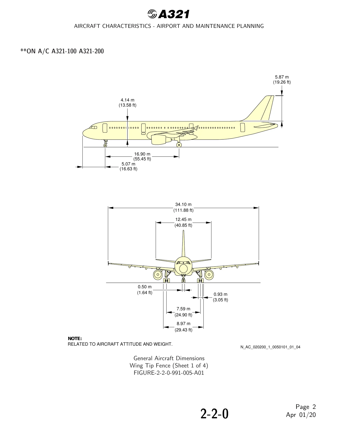
- General Aircraft Dimensions
- Ground Clearances
- Interior Arrangements – Plan View
- Interior Arrangements – Cross Section
- Cargo Compartments
- Door Clearances and Location
- Escape Slides
- Landing Gear
- Exterior Lighting
- Antennas and Probes Location
- Power Plant
- Leveling, Symmetry and Alignment
- Jacking
- Chapter 3 – Aircraft Performance
- General Information
- Payload / Range – ISA Conditions
- Take-Off Weight Limitation – ISA Conditions
- Take-Off Weight Limitation – ISA +15 degrees C Conditions
- Aerodrome Reference Code
- Landing Field Length – ISA Conditions
- Final Approach Speed
- Chapter 4 – Ground Maneuvering
- General Information
- Turning Radii
- Minimum Turning Radii
- Visibility from Cockpit in Static Position
- Runway and Taxiway Turn Paths
- Runway Holding Bay (Apron)
- Minimum Line-Up Distance Corrections
- Aircraft Mooring
- Chapter 5 – Terminal Servicing
- Aircraft Servicing Arrangements
- Typical Ramp Layout – Open Apron
- Typical Ramp Layout – Gate
- Terminal Operations – Full Servicing Turn Round Time
- Terminal Operations – Transit Turn Round Time
- Ground Service Connections Layout
- Grounding (Earthing) Points
- Hydraulic System Servicing
- Electrical System
- Oxygen System
- Fuel System
- Pneumatic System
- Oil System
- Potable Water System
- Waste Water System
- Engine Starting Pneumatic Requirements
- Ground Pneumatic Power Requirements
- Preconditioned Airflow Requirements
- Ground Towing Requirements
- De-Icing and External Cleaning
- Chapter 6 – Operating Conditions
- Engine Exhaust Velocities and Temperatures Contours – Ground Idle Power
- Engine Exhaust Velocities and Temperatures Contours – Breakaway Power
- Engine Exhaust Velocities and Temperatures Contours – Takeoff Power
- Danger Areas of Engines
- APU Exhaust Velocities and Temperatures
- Chapter 7 – Pavement Data
- General Information
- Landing Gear Footprint
- Maximum Pavement Loads
- Landing Gear Loading on Pavement
- Flexible Pavement Requirements – U.S. Army Corps of Engineers Design Method
- Rigid Pavement Requirements – Portland Cement Association Design Method
- Aircraft Classification Number – Flexible and Rigid Pavements
- Chapter 8 – Scaled Drawings
- Chapter 10 – Aircraft Rescue and Fire Fighting
Across these chapters, the Airbus A321 Aircraft Characteristics Airport and Maintenance Planning manual gives a technician or airport planner the exact figures they need to position the aircraft, plan stands and taxi routes, size ground support equipment and confirm servicing interface locations. Weight variant tables in the opening chapter set out Maximum Ramp Weight, Maximum Taxi Weight, Maximum Take-Off Weight, Maximum Landing Weight and Maximum Zero Fuel Weight for each A321-100, A321-200 and A321neo weight variant, so the aircraft being planned for can be matched to the correct variant data. Door identification drawings, cargo compartment locations, escape slide data and landing gear dimensions all follow with the same measurement-based approach.
Ground Operations and Maneuvering Data
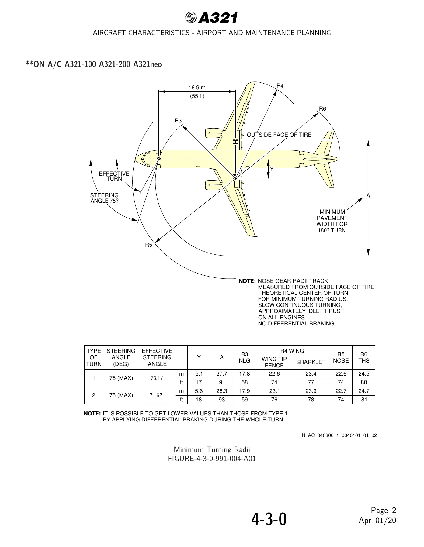
Ground maneuvering coverage is built around the geometry of the aircraft on the pavement. Turning radii charts show the path of the nose gear, main gear, wing tip and tail, while minimum turning radius diagrams add the effective steering angle and pavement width needed for a 180 degree turn. Separate turn-path drawings cover 135 degree and 90 degree turns from runway to taxiway and taxiway to taxiway, plus minimum line-up distance corrections for runway entry and runway turn pads. Cockpit visibility angles in the static position are charted for both vertical and horizontal fields of view so planners can judge clearance margins.
Ground clearances are given for each door, cargo door, flap track, aileron, spoiler, slat, APU and landing gear door position, with values shown for a maintenance configuration at mid CG, maximum ramp weight forward CG and maximum ramp weight aft CG. This makes the Airbus A321 Airport and Maintenance Planning manual a working reference for stand design and equipment reach rather than a generic specification sheet.
Terminal Servicing and Ground Support
The terminal servicing chapter maps every ground service connection on the aircraft, with access door numbers, distance aft of the nose, distance from the aircraft centerline and mean height from the ground. Hydraulic system panels for the green, yellow and blue systems, electrical external power receptacles, oxygen replenishment, refuel/defuel control panels and couplings, LP and HP pneumatic connectors, engine and IDG oil tanks, APU oil tank, potable water and waste water panels are all located. Typical ramp layouts for open apron and gate operations are also included, along with turn round time charts for full servicing and outstation transit scenarios.
Engine and Operating Condition Data
Engine and APU exhaust velocity and temperature contours are presented for ground idle, breakaway and takeoff power, alongside danger area diagrams showing intake suction and exhaust wake zones for the CFM56 series, IAE V2500 series, CFM LEAP-1A and PW 1100G engines. These diagrams support apron layout decisions, ground crew positioning and jet blast protection planning around the A321.
Pavement and Rescue Data
The pavement chapter provides landing gear footprint data, maximum pavement loads, flexible and rigid pavement requirements using the U.S. Army Corps of Engineers and Portland Cement Association methods, and Aircraft Classification Number tables for flexible and rigid pavements across the weight variants. Chapter 10 covers aircraft rescue and fire fighting material, including highly flammable and hazardous materials, battery locations, wheel and brake overheat safety areas, composite materials, emergency evacuation devices, doors and emergency exits, control panels and structural break-in points.
IMAGES PREVIEW
For anyone planning an A321 operation, this Airbus A321 Aircraft Characteristics Airport and Maintenance Planning manual is the document that answers the measurement questions: how far the wing tip swings in a turn, how high each door sill sits, where each servicing panel is, how much weight sits on each main gear leg, and what pavement strength is needed. The figures are tied to specific weight variants and CG positions rather than single averages, so the planning values stay accurate for the aircraft actually being handled. Because the A321 Airport and Maintenance Planning manual is delivered as an instant PDF download, there is no shipping and no waiting – you can open it on any device, print the pages you need for the ramp or planning office, and reference the diagram or table you need directly from the file.


Reviews
There are no reviews yet.