
Airbus A321 Structural Repair Manual 51-70-10 Repair Design Guideline PDF
Original price was: $39.95.$23.95Current price is: $23.95.
Airbus A321 Structural Repair Manual chapter 51-70-10 Repair Design Guideline, covering the reverse engineering method for static-strength repair design on extruded and formed sections, with eleven fully worked repair examples.
Description
Airbus A321 Structural Repair Manual 51-70-10 – Repair Design Guideline
This Airbus A321 Structural Repair Manual chapter 51-70-10 sets out the Repair Design Guideline used to establish the static strength capability of a repair when the applied loading on the repaired part is not known. It documents the reverse engineering method – the approach in which the allowable load of the original, pre-damaged structure is calculated first and the repair is then sized to restore that capability. The guideline is written for extruded and formed sections and walks through tension, shear, compression/crippling and fastener checks step by step.
Because the method restores original static strength, the resulting repair complies with the static strength requirements, and when used together with the other standard SRM principles and guidelines (fastener hole and drill data, spacing and margin data, sealing and so on) the repairs can be applied to secondary structure without referring back to AIRBUS. The document notes plainly that repairs designed this way may also be submitted for approval, but that the assumptions taken under the reverse engineering method are often conservative and can lead to over-designed repairs.
File Details
- Manual type: Structural Repair Manual – Repair Design Guideline (Chapter 51-70-10)
- Brand / aircraft: Airbus A321
- Language: English
- Page count: 118 pages
- File format: PDF
- Chapter reference: 51-70-10
- Date shown on document: Jun 01/09
Chapters Covered
- General
- Purpose of the Repair Design Guideline
- Scope and Limitations
- Factor Definitions – Safety Factor, Reserve Factor, Margin of Safety
- Principle – Repair Material and Dimensions, Analysis
- Tension and Shear Check
- Compression Check
- Fastener Check
- Allowable Compressive Load – crippling factor K and calculation method
- Calculation
- Calculation under Tensile Load – maximum tensile load, reserve factor, fastener number
- Calculation under Shear Load – maximum shear load, reserve factor, fastener number
- Determination of Shear or Bearing Critical for Sections in Double Shear
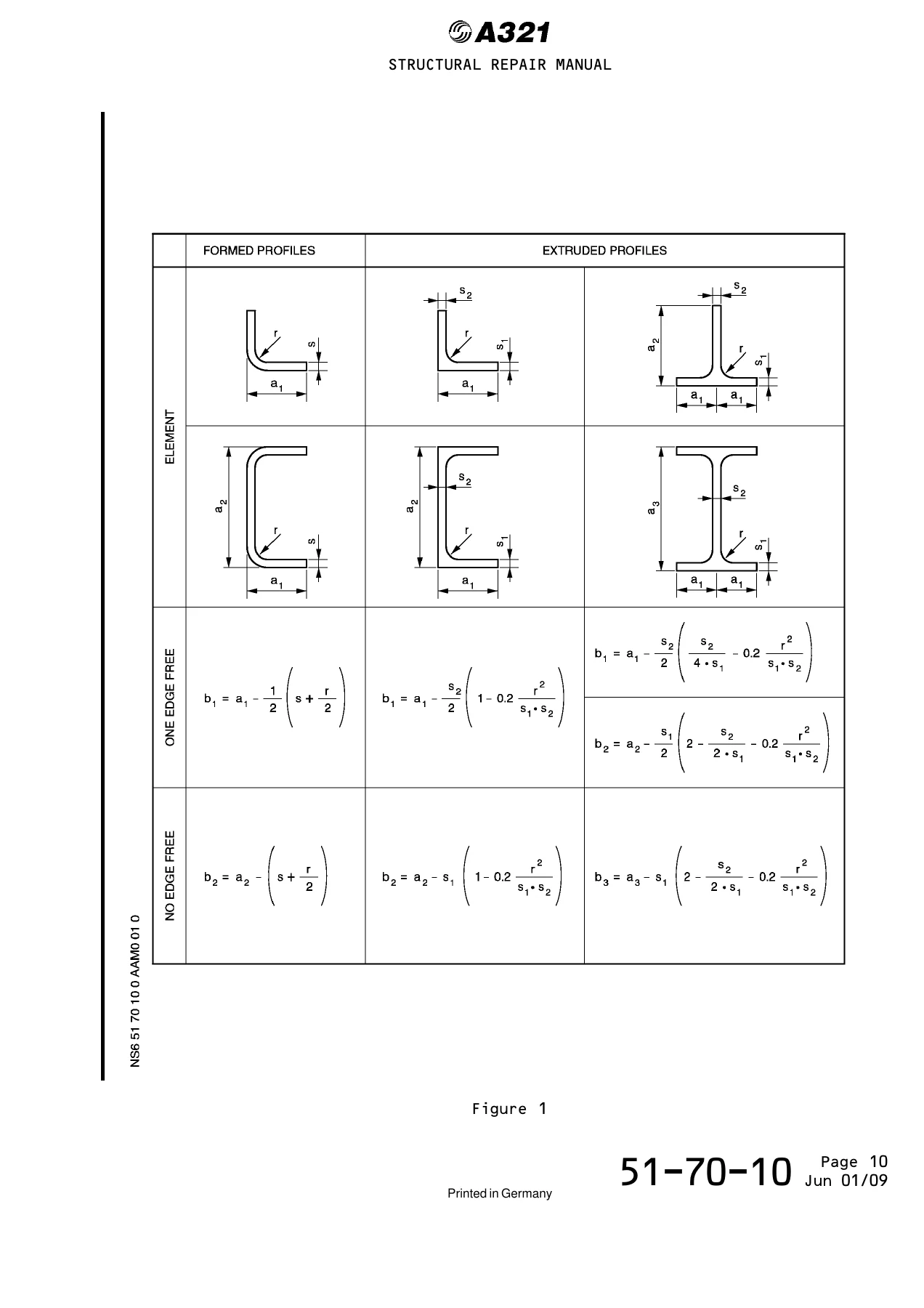
- Calculation under Crippling Load – calculated element breadth, element crippling stress, element crippling load, profile crippling load
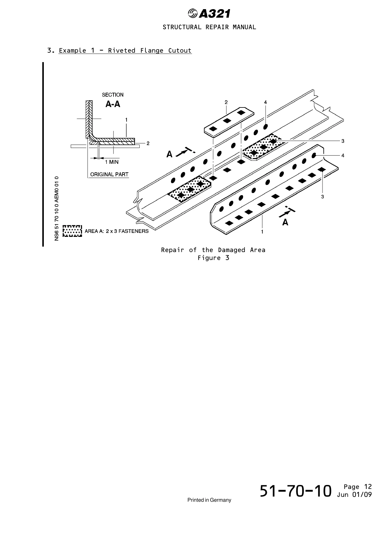
- Example 1 – Riveted Flange Cutout
- Example 2 – Extrusion Cutout
- Example 3 – Complete Extrusion Cutout
- Example 4 – Profile Cutout
- Example 5 – Profile Cutout
- Example 6 – Typical T-Profile Cutout
- Example 7 – Typical C-Type Beam Upper Flange Cutout
- Example 8 – Typical Formed Section Cutout
- Example 9 – Typical Formed Section Cutout
- Example 10 – I-Type Beam Upper Flange Cutout
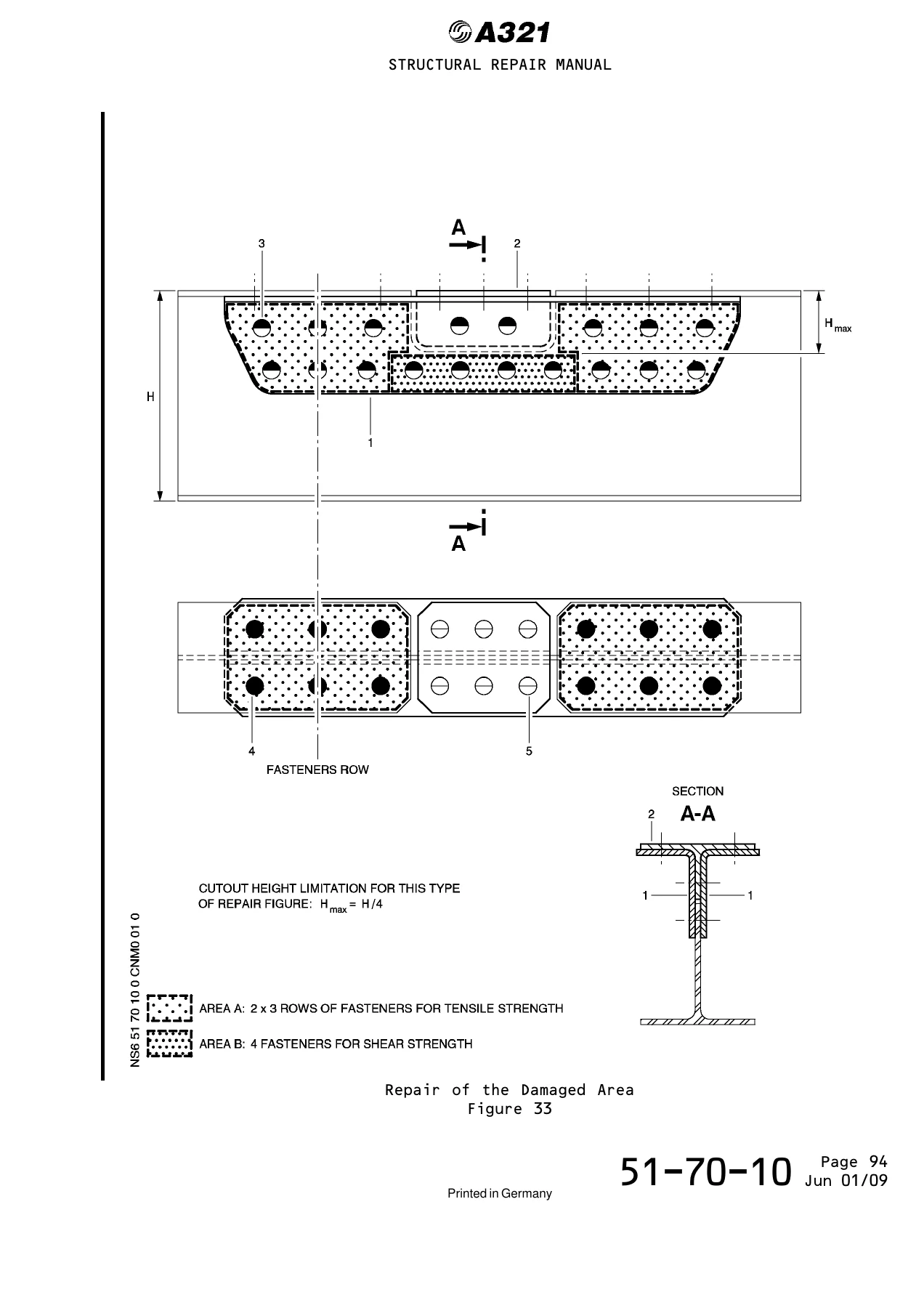
- Example 11 – Web Repair (Limited Cutout Height)
- Web Repair – Unlimited Cutout Width
Beyond the chapter list, this document is essentially a working calculation handbook. It begins with the reasoning behind the guideline – why a static or stress analysis is performed, why the reverse engineering route is taken when the applied loading details are unknown, and how reserve factor and margin of safety are defined in aircraft design terms (factor of safety 1.5, ultimate load = 1.5 x limit load, R.F. greater than or equal to 1.00, M.S. greater than or equal to 0). From there it lays out the material and dimensional principle: use the same material as the original, restore the original cross-sectional area, and generally go one gauge thicker. It then defines exactly which section is considered for the pre-damaged allowable load – the original net section for profiles, the repair net section for plates and webs – and explains why repair fastener holes are deliberately excluded from the original-part calculation so that the maximum potential strength of the original part is not underestimated.
The calculation section then gives the formulas themselves: Pmax = A x (Ftu or 1.5 x Fty, whichever is less) for tension, Psmax = A x Fsu for shear, the double-shear fastener allowable Fds = 2 x c x Fss, and the bearing-based allowable Pallow = s x d x Fbru. The crippling section details the empirical method for short metal profiles of general shape, in which the profile is idealised as flat rectangular plates of constant thickness and the profile crippling load is the sum of the crippling loads of all rectangular elements. Crippling factors are given for one edge free (K = 0.41) and for no edge free where a1 – s1 > 0.2 x a2 (K = 3.6). The document also states the slenderness limits within which the crippling method applies – one edge free a/s less than or equal to 12, no edge free a/s less than or equal to 25 – and warns that for longer profiles section buckling must be investigated separately.
The worked examples are the real substance of the guideline. Each one takes a specific cutout configuration, states the original part material and the doubler material with full allowable tables (Ftu, Fty, mini Ftu or 1.5 x Fty, Fcy, Fsu, Fbru, Ec), documents the fasteners and rivets used with their ultimate handling force, and then runs the tensile calculation, the reserve factor check, the fastener row determination and the crippling verification in sequence. Configurations include a riveted flange cutout on 2024-T42 clad sheet, an extrusion cutout and a complete extrusion cutout on 7075-T6511, several profile cutouts on sheet and extrusion material, a typical T-profile, a C-type beam upper flange cutout where the flange width had to be increased from 6 mm to 7 mm following the crippling calculation, formed section cutouts, an I-type beam upper flange cutout with double-shear web fasteners, and web repairs with both limited cutout height and unlimited cutout width. Interpolation and extrapolation of tabulated crippling loads is demonstrated numerically, and bearing verification is shown explicitly with the check that Fbru max is compared against Fbru allow so the lower value governs the allowable fastener load.
What This Guideline Enables
- Sizing a doubler repair so that the repaired section restores the original static strength of the cutout area
- Running the tension, shear, bearing and crippling checks required for a repair substantiation
- Determining the number of fastener rows required from the original maximum load and the ultimate handling force per row
- Selecting fastener type and diameter, including Hi-Lok replacements for existing rivets and double-shear configurations in webs
- Deciding whether a section is shear critical or bearing critical in double shear
- Calculating profile crippling load element by element for formed and extruded shapes
- Checking whether a doubler flange is wide enough to support the adjacent element using the a1 – s > 0.2 x a2 criterion
- Verifying slenderness ratios against the buckling limits before relying on a crippling result
Each example closes with the standard shop notes that must accompany the repair – wet assembly with PR 1436G, breaking sharp edges, dimensions in millimetres, parts adjusted on aircraft, and the SRM rule references for fastener hole and drill data, oversize and alternative fasteners, spacing and margins, paint coating, sealing processes, countersinking and torque values. The bend radius requirement that the outside radius of the inner nesting part must be greater than the inside radius of the adjacent part is repeated with each repair.
IMAGES PREVIEW
Anyone producing or reviewing a structural repair on an A321 extruded or formed section will find the method, the formulas, the material allowables and a matching worked example here rather than having to derive the approach from scratch. The instant PDF download can be opened on any device and printed for use at the bench or in the office, with no shipping and no waiting.
Reviews
There are no reviews yet.